

Abstract
Transpiration cooling is considered to be one of the most effective cooling methods for protecting components from ablation in extremely high temperature environments, so improving transpiration cooling efficiency is quite useful in practical applications. Living creatures always have the optimal properties for cooling after long-term evolution. This study proposes a novel transpiration cooling concept using a biomimetic non-smooth surface inspired by the earthworm's rough skin. The transpiration cooling efficiencies of porous plates with three different bio-inspired non-smooth surfaces - isosceles-trapezoid, right-angled-trapezoid and parallelogram grooves -are numerically investigated. The numerical model is validated by experimental data. The structure of the non-smooth surface dramatically affects the film thickness and surface heat convection intensity of transpiration cooling. The cooling efficiency is significantly improved by the parallelogram style non-smooth surface. The bio-inspired non-smooth surface successfully thickens the protective film and achieves a significantly better cooling performance. The protective film of transpiration cooling is thickened 22.7% while the transpiration cooling efficiency is significantly increased by 12% with the assistance of the bio-inspired non-smooth surface.
Export citation and abstract BibTeX RIS
Nomenclature
| p | Pressure [Pa] |
| u | velocity [m s−1] |
| T | Temperature [K] |
| h | Heat transfer coefficient in the fluid [W (m2 · K)−1] |
| K | Permeability [m2] |
| F | Inertial coefficient |
 | Dynamic viscosity [Ns m−2] |
| ρ | Mean fluid density [kg m−3] |
 | Thermal conductivity [W (m · K) −1] |
 | Porosity |
 | Shear stress tensor [Pa] |
 | Oling effectiveness |
 | Thermal conductivity [W (m · K)−1] |
| w | Wall |
| C | Coolant |
 | Main stream |
| f | Fluid |
| eff | Effective |
| d | Dispersion |
1. Introduction
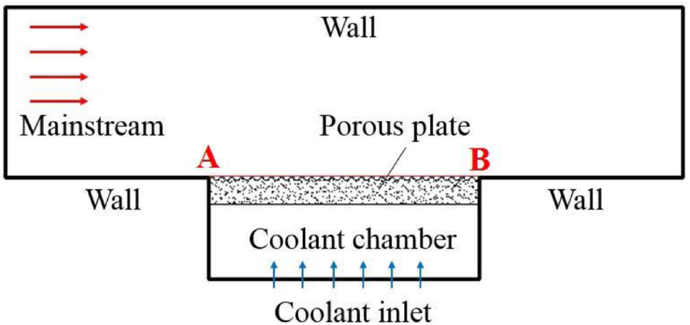
Thermal protection of hypersonic vehicles has become a huge challenge with the development of the aerospace industry. Some of the key components experience tremendous heat fluxes, especially in combustion chambers of engines. The maximum temperature in the combustion chamber of a liquid-fueled rocket is about 3600 K [1]. The heat fluxes in a scramjet combustion chamber even reach 23.44 MW m−2 [2]. Existing materials find it difficult to withstand such high temperatures for a long time. Transpiration cooling is one of the most effective methods for protecting components exposed to high temperature environments from ablation [3]. The schematic of the transpiration cooling method is illustrated in figure 1. The hot mainstream heats the surface by heat convection. A low temperature coolant flows through the porous media wall and removes heat with a high efficiency. The porous zone usually contains a large number of micro-pores with diameters ranging between 5 µm and 200 µm. The coolant then flows out of the porous zone and forms a protective film on the hot side surface, which effectively reduces the heat transfer from the hot mainstream to the surface. Transpiration cooling thus has a very high efficiency owing to the above two mechanisms.

Figure 1. Schematic of the transpiration cooling geometry.
Download figure:
Standard image High-resolution imagePrevious research on transpiration cooling mainly focused on the porous material and the coolant. The most common porous materials used for transpiration cooling are sintered metal particles [3, 4], sintered ceramic particles [5, 6], sintered metal fibers [7, 8] and ceramic matrix composites [9, 10]. More recently, metal additive manufacturing technology was applied to fabricate the porous material for transpiration cooling which achieved both a high cooling efficiency and a high mechanical property [11, 12]. Physical properties and pore structures of porous materials have been well studied to improve cooling efficiency for practical applications. Different kinds of coolants have been investigated to improve the efficiency and stability of transpiration cooling. The common gaseous coolants of transpiration cooling include air, helium and nitrogen. Much research has indicated that a higher heat capacity of the gaseous coolant results in a higher transpiration cooling efficiency [13–15]. Several recent research papers applied liquid coolant, such as water, for transpiration cooling. The large latent heat of phase change of water led to a higher cooling efficiency [3, 16, 17]. However, the phase change process also brought some unsteady problems to the transpiration cooling systems, such as temperature oscillation and significant cooling delay [18]. A biomimetic tree transpiration method [19–21] and hydrogel [22] were investigated to achieve better stability.
The weight of the coolant carried by the hypersonic vehicle is limited due to the limited space, economics and many other factors in practical applications. Thus, improving transpiration cooling efficiency is important to practical applications. Previous research on improving transpiration cooling efficiency mainly focused on porous media materials and coolants. However, the transpiration cooling efficiency was difficult to be further substantially improved by changing the porous materials or coolants due to the limited options. A novel method is necessary to improve transpiration cooling efficiency.
In nature, animals always have the optimal properties after long-term evolution. A good example is the non-smooth surfaces of soil-burrowing animals, such as earthworms and dung beetles. Their non-stick surfaces have a small friction due to their non-smooth surfaces [23–25]. Many experimental and numerical studies have proved that surface friction can be significantly reduced by bio-inspired non-smooth surfaces [26–28]. According to the Reynold's analogy, heat convection intensity on surfaces was positive to the surface friction [29, 30], which means that heat convection intensity on the surface decreases with decreasing the surface friction. In this way, the bio-inspired non-smooth structure can be a promising way to improve transpiration cooling efficiency by reducing convection heat from the hot mainstream to the heated surface.
Figure 2 illustrates schematics of mucus secretion of an earthworm and transpiration cooling of a porous plate. The process of earthworm mucus secretion is very similar to transpiration cooling. Earthworms separate soil from their skin by secreting mucus to protect themselves and reduce moving friction. Similarly, transpiration cooling isolates the high temperature mainstream from the surface by injecting a protective film on the surface to reduce heat flux and thermally protect the surface. Micro-grooves prevent soil sticking to earthworm surfaces and prevent mucus from being quickly taken away by soil. Thus, the earthworm is well protected by its non-smooth skin and easily moves in the harsh soil environment. The excellent advantage of earthworm non-smooth skin highly inspires this study. Biomimetic micro-grooves are designed on a porous surface as shown in figure 2. The bio-inspired non-smooth surface is expected to improve transpiration cooling efficiency by preventing the protective film from being quickly taken away by the harsh hot mainstream. To the knowledge of the authors, this is the first investigation on improving transpiration cooling efficiency using biomimetic structured surfaces.

Figure 2. Schematics of mucus secretion on the earthworm skin and transpiration cooling on the bio-inspired non-smooth porous surface.
Download figure:
Standard image High-resolution imageThis study mainly applies computational fluid dynamic (CFD) methods to investigate the transpiration cooling effects of bio-inspired non-smooth surfaces. Three different non-smooth surfaces are designed and numerically investigated under different conditions using the validated numerical model. The mechanism by which the non-smooth surface influences the transpiration cooling was analyzed. The geometric parameters were then optimized by CFD method to achieve a better performance.
2. Models of bio-inspired non-smooth surfaces
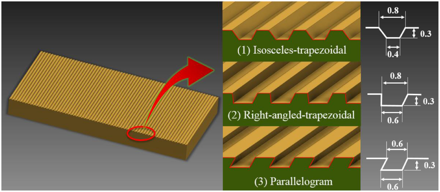
Three different non-smooth structures with isosceles-trapezoidal grooves, right-angled trapezoidal grooves and parallelogram grooves are designed and investigated in this study as shown in figure 3. The micro-grooves are perpendicular to the hot mainstream. The shapes and sizes of the micro-grooves in this study are shown in figure 3. The whole porous plate is 80 mm × 40 mm × 8 mm (length, width and thickness). The transpiration cooling effect with a conventional smooth surface is also tested and simulated to compare with the non-smooth surfaces.

Figure 3. Models of bio-inspired non-smooth surfaces (unit: mm).
Download figure:
Standard image High-resolution imageA numerical method was applied to investigate the transpiration cooling effect. In order to validate the numerical model, a smooth surface sample and a non-smooth surface sample were fabricated and tested in a hot wind tunnel. A porous plate with an isosceles-trapezoid style non-smooth surface, as shown in figure 3(1), was fabricated using metal injection molding (MIM) technology and metal sintering technology. Figure 4 shows photographs of the sintered bronze porous plate with the isosceles-trapezoid style non-smooth surface. A mold with the desired non-smooth surface shape was pre-fabricated for the MIM. The plate was made of bronze particles with average diameters  = 45 µm. The average porosity is about 40% was measured by a mercury porosimeter. A porous plate with a smooth surface was also fabricated as the control group as shown in figure 4. Transpiration cooling effects of the porous samples in figure 4 were tested in the hot wind tunnel in Tsinghua University [18]. The numerical model was then validated against the experimental data of the isosceles-trapezoidal style non-smooth surface and the smooth surface.

Figure 4. Photographs of the sintered bronze porous plates with smooth and non-smooth surfaces.
Download figure:
Standard image High-resolution imageIn this study, we only fabricated the porous plates with the isosceles-trapezoid style non-smooth surface and the smooth surface as shown in figure 4 due to the limitations of the MIM manufacturing technique and economic cost. The other non-smooth surfaces are difficult to fabricate using a mold due to the limitation of the draft angle. Thus, the validated CFD method is applied to investigate the performances of the right-angled-trapezoidal structure and the parallelogram structure. The parameter optimization is also conducted with the assistance of the CFD method.
3. Numerical method
3.1. Physical model and governing equations
The transpiration cooling of the porous plates with the isosceles trapezoidal, right-angled-trapezoidal and parallelogram style non-smooth surfaces and smooth surface are modeled and numerically investigated using the 2D model shown in figure 5. The 2D model has been proved to be a reliable method to simulate the transpiration cooling [13, 16, 17, 32, 33]. The structure and sizes of the non-smooth structures are illustrated in figure 3. The mainstream channel is 50 mm high and the porous plate is 80 mm long, the same dimensions as the wind tunnel and the experimental plate. The coolant is air with real-gas thermodynamic properties, such as thermal conductivity, viscosity and specific heat. The transpiration cooling blowing ratio is defined as:
where  is coolant density,
  is average coolant velocity,
  is mainstream density and
  is the average mainstream velocity. The non-dimensionless blowing ratio F indicates the coolant consumption relative to the mainstream. The local cooling efficiency is defined as:

where  is the wall temperature of porous plates,
  is the mainstream temperature, and
  is the inlet temperature of coolant.

Figure 5. Numerical model of transpiration cooling.
Download figure:
Standard image High-resolution imageThe steady governing equations for the mainstream include the continuity, momentum and energy equations. The equations written in tensor form are:


where ρ is the density, P is the pressure, Di,j is the diffusion coefficient and E is the total energy. The porous media is assumed to be homogeneous. The Forchheimer–Brinkman extended Darcy equation is used in the porous zone:

where ε is the porous media porosity. The above momentum equation for the porous media considered the inertial effects and viscous dissipation effects based on the Darcy equation. The permeability, K, and the inertia coefficient, F, are given by Ergun as [31]:


The energy equation in the porous zone is based on the local thermal equilibrium model (LTE). The solid matrix temperature and the fluid temperature are assumed to be locally the same in the LTE model. Previous studies have shown that the LTE model predicted well the heat transfer process in the porous media for transpiration cooling [13, 32, 33]:

Wang et al [34] derived a criterion for using the above LTE model. The criterion is satisfied for all the numerical cases in this study. The LTE model has been proven to be effective for transpiration cooling when coupling the porous zone with the mainstream zone. The equivalent thermal conductivity of the porous media, λm, and the additional thermal conductivity, λd, due to the thermal dispersion effect are defined as [35]:

The ANSYS ICEM software package is used to mesh the physical model. The mesh elements are concentrated on the wall boundary and the porous surface where the velocity and temperature have significant gradients. A mesh adaption function is used to refine the mesh around micro-grooves of the non-smooth surfaces. Figure 6 shows the mesh near the isosceles trapezoid style non-smooth surface. The governing equations for the flow and temperature fields are then solved by ANSYS FLUENT 14.0 based on the finite volume method (FVM) with about 640 000 structured elements after grid independence tests.

Figure 6. Mesh on the isosceles trapezoid style non-smooth surface.
Download figure:
Standard image High-resolution imageThe mainstream inlet boundary condition is the 'velocity inlet' with a speed of 40 m s−1, a temperature of 775 K and a pressure of 0.1 MPa. The mainstream outlet boundary condition is the 'pressure outlet'. The coolant inlet boundary condition is the 'mass flow inlet' with a temperature of 300 K. The value of the mass flux of the coolant depends on different blowing ratios. The flow directions of the mainstream and coolant are both perpendicular to their inlet boundaries. The boundary of the porous plate is set to be 'internal face' which is highly coupled with the mainstream and coolant. The walls of the mainstream zone are assumed to be adiabatic and non-slip. The mainstream and the coolant are both air. The 'ideal gas model' is used for the fluid physical properties. A steady-state pressure-based model is used to solve the non-linear governing equations. A second-order upwind scheme is used to discretize the convection terms. The y+ of the first layer of elements is around 1 near the wall. The pressure-velocity coupling method is SIMPLE arithmetic. The under-relaxation factor for the pressure equation is 0.3. The convergence criterion is that all the residuals are smaller than 10−5. The model is simulated with different turbulence models with the predictions then compared to the experimental results.
3.3. Validation of the numerical model
The numerical model is validated against the experimental data of the isosceles-trapezoidal style non-smooth surface and the smooth surface. Navier–Stokes equations are solved using the standard k–ε model or SST k–w turbulence model. The Forchheimer–Brinkman extended Darcy equation is solved to simulate the flow in the porous zone. The numerical results with different turbulence models are compared to the experimental results as shown in figure 7. Table 1 shows the average and maximum errors between the numerical and experimental results when blowing ratio F = 3.5%. The standard k–ε turbulence model gives much better predictions than the SST k–w turbulence model. The average error and maximum error are 3.7% and 8.2%, respectively, for the smooth surface when using the standard k–ε model. The average error and the maximum error are 3.1% and 7.1%, respectively, for the non-smooth surface when using standard k–ε model. Figure 8 shows the comparison for the average cooling efficiency with a coolant blowing ratio range of 2%–5%. The simulation results of the 2D numerical model with standard k–ε model corresponds well with the experimental data for both the smooth and non-smooth models with different blowing ratios. The validated numerical model is then applied to investigate the transpiration cooling effects with different non-smooth structures.

Figure 7. Comparisons of numerical and experimental results for the cooling efficiency distributions along the porous plates with the non-smooth and smooth surfaces when F = 3.5%. (a) Smooth surface. (b) Non-smooth surface.
Download figure:
Standard image High-resolution imageTable 1. Comparison between the numerical and experimental results.
| Standard k–ε | SST k–w | |||
|---|---|---|---|---|
| Average error | Maximum error | Average error | Maximum error | |
| Smooth surface | 3.7% | 8.2% | 7.2% | 23.5% |
| Non-smooth surface | 3.1% | 7.1% | 23% | 31.3% |

Figure 8. Comparisons of numerical and experimental results for the average cooling efficiencies of the porous plates with the non-smooth and smooth surface for different blowing ratios. (a) Smooth surface. (b) Non-smooth surface.
Download figure:
Standard image High-resolution image4. Results and discussion
4.1. The performance of transpiration cooling with biomimetic non-smooth surfaces
The transpiration cooling of the porous plates with the three non-smooth surfaces are simulated by the validated numerical model. Figure 9 shows the cooling efficiencies of the non-smooth surfaces compared with that of the smooth surface for coolant blowing ratios of F = 2.0% and 3.5%. The mainstream velocity and temperature are kept constant for all cases with  = 40 m s−1 and
  = 775 K. The coolant flows through the porous plate to remove the heat and then forms a protective film on the surface. The mainstream flows from the left to the right side. The surface cooling efficiency increases along the mainstream direction due to the cumulative effect of the protective film layer, but the cooling efficiency gradient is small due to high thermal conductivity of bronze. When the blowing ratio is F = 2.0%, the transpiration cooling efficiencies of the three porous plates with the non-smooth surfaces are both less than the smooth surface. When the blowing ratio further increases to F = 3.5%, the parallelogram style non-smooth surface presents a significantly higher cooling efficiency than the smooth surface as shown in figure 9(b). The bio-inspired parallelogram style non-smooth surface delivers an expected improvement on transpiration cooling efficiency. The cooling efficiency distributions on the non-smooth surface are also more homogeneous than the smooth surface.

Figure 9. Transpiration cooling efficiency distributions along porous plates with different surface structures. (a) Blowing ratio F = 2.0% (b) Blowing ratio F = 3.5%.
Download figure:
Standard image High-resolution imageHowever, the average cooling efficiency of the isosceles-trapezoid style and right-angled-trapezoid style non-smooth surfaces are always lower than that of the smooth surface, which means that both the isosceles-trapezoid and isosceles-trapezoid non-smooth surfaces fails to deliver the desired result of improving cooling efficiency. The non-smooth surface has two counter-acting influences on the transpiration cooling. The grooved surface prevents the coolant from being quickly removed by the mainstream and thicken the film, which is good for the transpiration cooling efficiency. On the other hand, however, the non-smooth surface also enhances the interaction between the hot mainstream and the porous plate, which increases the heat flux and is bad for the transpiration cooling effect. There is a trade-off for the non-smooth surface. The mechanism of the effect of the non-smooth surface on the cooling efficiency will be analyzed based on fundamental aspects from the fluid mechanics and heat transfer in the following sections.
4.2. The mechanism of the effect of biomimetic non-smooth surface on transpiration cooling
Transpiration cooling includes two cooling processes. Firstly, the coolant flows through the porous media to directly cool the solid matrix by heat convection. Secondly, the coolant flow forms a protective film on the porous surface after flowing out from the porous media, which reduces the heat flux from the mainstream to the surface. The porous media characteristics of porous plates (thickness, porosity, material etc) for different surface structures are the same in this study, so the heat convection processes inside these porous plates should be similar. Thus, their different cooling efficiencies are mainly caused by their different protective film layers on the different non-smooth surfaces.
Figure 10 shows the protective film layer distributions on the porous plates with the different surface structures. The film layers effectively isolate the porous plates from the mainstream, which reduces the heat flux from the mainstream to the porous plates. The non-smooth surfaces significantly affect the film layer thickness and the interactions between the hot mainstream and the porous surface. Figure 10 shows that the protective films on the non-smooth surfaces are significantly thicker than that on the conventional smooth surface. The biomimetic non-smooth surface achieves the desired effect of increasing the film thickness and preventing the film from being quickly taken away by the hot mainstream. The maximum film thicknesses of different structures and coolant injection ratios are listed in table 2. When the coolant injection ratio is F = 2.0%, the maximum film thickness on the smooth surface is 2.44 mm while the maximum film layer thicknesses on the isosceles trapezoidal and parallelogram non-smooth surfaces are 3.58 mm and 3.37 mm, respectively, which are 46.7% and 38.11% thicker than those on the smooth surface. The average and maximum film layer thicknesses increase with increasing the blowing ratio. For the 3.5% blowing ratio, the maximum film layer thicknesses on the isosceles trapezoidal and parallelogram non-smooth surfaces are 39.4% and 22.7% thicker than on the smooth surface, respectively. The non-smooth surfaces effectively hold the film on the surfaces and thicken the film layer compared to the smooth surface. The thickened film contributes to better protection. The isosceles-trapezoidal style surface always has a thicker film than the parallelogram non-smooth surface because the coolant jet direction of the parallelogram groove is inclined to the surface.

Figure 10. Protective films on the porous plates with different surface structures. (a) Blowing ratio F = 2.0%. (b) Blowing ratio F = 3.5%.
Download figure:
Standard image High-resolution imageTable 2. Maximum thicknesses of film layers.
| Smooth surface | Non-smooth surface: isosceles trapezoid style | Non-smooth surface: parallelogram style | |||
|---|---|---|---|---|---|
| Thickness (mm) | Thickness (mm) | Improvement (%) | Thickness (mm) | Improvement (%) | |
| F = 2.0% | 2.44 | 3.58 | 46.7 | 3.37 | 38.1 |
| F = 3.5% | 3.60 | 5.02 | 39.4 | 4.42 | 39.4 |
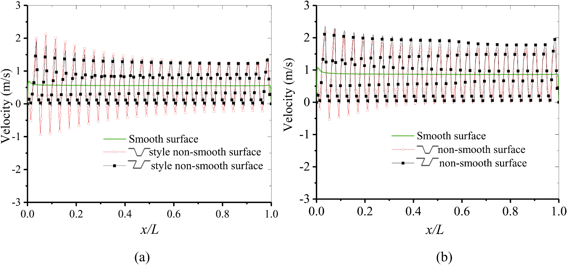
The protective films on the non-smooth surfaces are significantly thicker than that on the smooth surface owing to the inhomogeneous velocity distributions on the non-smooth surface. Figure 11 shows the vertical velocity distributions on the top surfaces of the porous plates (the line AB is marked in figure 5) with non-smooth and smooth surfaces. A positive value of the velocity indicates upward flow while a negative value indicates downward flow. The vertical velocity distribution on the smooth surface is uniform because the pressure difference between the two sides of the porous plate is uniform along the mainstream direction. However, the vertical velocity distribution along the non-smooth surface is quite inhomogeneous with dramatic variations around an average value. The coolant tends to flow out from the bottoms of the micro-grooves due to the smaller flow resistance. Thus, the non-smooth surfaces have significant inhomogeneous velocity distributions. The maximum vertical velocity of the non-smooth surface is larger than that of the smooth surface; thus, the mainstream is pushed farther up by the coolant with the higher vertical velocities which then thickens the protective film on the non-smooth surface more, compared to the smooth surface.

Figure 11. Vertical velocity distributions on the top planes of the porous plates. (a) Blowing ratio F = 2.0% (b) Blowing ratio F = 3.5%.
Download figure:
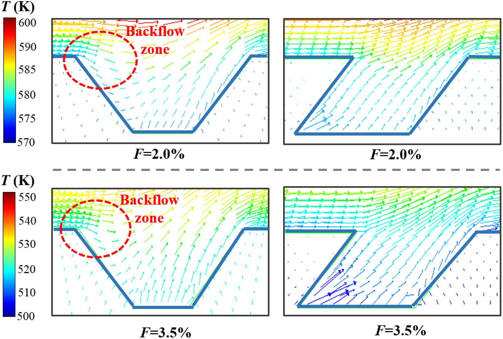
Standard image High-resolution imageThe thicker protective film on non-smooth porous plates reduces the heat transfer from the high temperature mainstream to the porous plate. However, the influence of the non-smooth surface on the interaction between the hot mainstream and the porous surface also plays an important role in affecting the transpiration cooling effect. The porous plate is heated by the convection from the hot mainstream. The different non-smooth structures have different effects on the flow field and the convection heat transfer. The vertical velocities are negative on some parts of the isosceles-trapezoidal style non-smooth surface as shown in figure 11, which means that the hot gas flows back into the grooves in those areas. Figure 12 shows the flow fields around the micro-grooves. The velocity vectors are colored according to temperature. A remarkable backflow appears on the left side of the isosceles-trapezoidal groove. The backflow brings the higher temperature gas back into the grooves, which increases the convection heat transfer between the hot gas and the porous plate. The backflow has a bad influence on transpiration cooling. Therefore, the transpiration cooling efficiency of the isosceles-trapezoidal non-smooth surface does not improve the transpiration cooling efficiency even though it has a thicker film.

Figure 12. Flow fields in the grooves (colored by temperature).
Download figure:
Standard image High-resolution imageThe parallelogram style non-smooth surface also has slight backflow when the blowing ratio is 2.0%. The vertical velocities out of the grooves became larger when the blowing ratio increases to 3.5%. The larger vertical velocity better pushes the hot mainstream out of the groove and the backflow region then totally disappears in the parallelogram groove as shown in figure 12. Thus, the parallelogram style non-smooth surface has a slightly lesser influence on the interaction between the mainstream and porous surface compared to the isosceles-trapezoidal style non-smooth surface. The parallelogram style non-smooth surface effectively thickens the film layer with a slight influence on the interaction between the mainstream and porous surface. The effect of parallelogram style non-smooth surface is similar to the skin of an earthworm. The mucus is effectively kept on the earthworm by non-smooth skin. The transpiration cooling coolant is also effectively kept on the porous surface by the micro-grooves. The thicker film layer is beneficial for reducing the heat transfer from the harsh hot environment to the surface. Thus, the parallelogram style non-smooth surface effectively improves the transpiration cooling efficiency. For the isosceles trapezoidal style non-smooth surface, the bad effect of non-smooth surface structure dominates which always significantly aggravates the convection heat transfer to the surface, so the transpiration cooling efficiencies on the isosceles-trapezoidal style non-smooth surface are always less than those on the smooth surface. This section explains the mechanism of the effect of non-smooth surfaces on cooling efficiency based on fundamental aspects from the fluid mechanics and heat transfer.
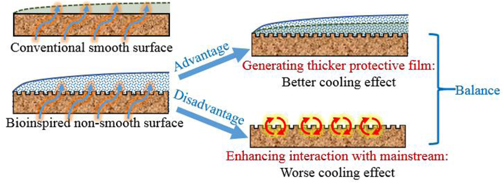
The mechanism of the bioinspired approach for transpiration cooling is summarized and illustrated in figure 13. The protective film is very important for transpiration cooling. The bioinspired approach aims at improving the protective film layer and cooling efficiency. Micro-grooves are designed and fabricated on the surface inspired by the non-smooth skin of the earthworm. The investigation results show that bioinspired non-smooth surfaces indeed thicken the protective film, which is the main advantage of this bioinspired approach. However, non-smooth surfaces unavoidably enhance the interaction between the surface with the hot mainstream, which is bad for the transpiration cooling effect. Thus, there is a balance between the advantage and disadvantage of this bioinspired approach. The shape and size of the micro-grooves should be carefully designed and optimized to solve this trade-off problem.

Figure 13. Mechanism of bioinspired approach for transpiration cooling.
Download figure:
Standard image High-resolution image4.3. Optimization of the parallelogram style non-smooth structure
A preliminary optimization of the geometric parameters of the parallelogram style non-smooth surface is then conducted by CFD method. Figure 14 shows the transpiration cooling efficiencies for the parallelogram style non-smooth surfaces with different parameters. The gap length of shape A is 0.3 mm, that of shape B is 0.6 mm, which is the original shape investigated in the previous sections, and that of shape C is 1.2 mm. Table 3 lists the average cooling efficiencies of the different parallelogram style non-smooth surfaces and the smooth surface. The size of the parallelogram style groove has a significant influence on transpiration cooling effect. The average transpiration cooling efficiency of shape A is lower than the conventional smooth surface. Shapes B and C both have higher cooling efficiencies than the smooth surface. The transpiration cooling efficiency is significantly improved by the bio-inspired non-smooth surfaces containing the shapes B and C.

Figure 14. Transpiration cooling efficiencies for parallelogram style non-smooth surfaces with different size slots (unit: mm).
Download figure:
Standard image High-resolution imageTable 3. Average cooling efficiencies of smooth and parallelogram style non-smooth surfaces.
 |
Improvement of  |
|
|---|---|---|
| Smooth surface | 0.623 | — |
| Shape A | 0.591 | −5.3% |
| Shape B | 0.657 | 5.5% |
| Shape C | 0.698 | 12.0% |
The protective film distributions of shapes A, B and C are similar, as shown in figure 15. The size of the parallelogram style micro-groove has a slight influence on the film thickness. The groove size significantly affects the specific area of heat convention. The specific area of shape A is notably larger than shapes B and C, which leads to a more intense interaction between the hot mainstream and the porous surface. Thus, the transpiration cooling efficiency of shape A is lower than that of the shape B, shape C and smooth surface. The specific area and the thermal convection to the porous surface decrease with increasing gap length from 0.3 mm to 1.2 mm. Thus, the transpiration cooling efficiency significantly increases with increasing gap length from 0.3 mm to 1.2 mm. The transpiration cooling efficiency is relatively improved by approximately 12% by the shape C bio-inspired non-smooth surface.

Figure 15. Protective films of different parallelogram style shapes.
Download figure:
Standard image High-resolution image
The above preliminary optimization results encourage the research of transpiration cooling with bio-inspired non-smooth surfaces. Transpiration cooling efficiency can be effectively improved by using suitable bio-inspired surfaces. The cooling efficiency still has the potential to be further improved to a new milestone with a global optimization. The key parameters of the micro-groove which need to be optimized are the shape, height, width, spacing and inclined angle. Further research will focus on building a global optimization algorithm to search the optimal parameters. The feasibility of fabrication also needs to be considered during the optimization.
5. Conclusions
This study proposes a novel concept of using non-smooth surfaces to improve the transpiration cooling efficiency inspired by earthworm skin. Various biomimetic non-smooth surfaces are numerically investigated. The validated CFD model is used to reveal the mechanism of the non-smooth surface and to optimize the parameters. The main results are: The non-smooth surface has two counter effects on the transpiration cooling. The non-smooth surface made the protective film thicker, which is good for transpiration cooling. However, the non-smooth surface also increased the thermal convection between the hot mainstream and the porous plate, which is bad for transpiration cooling. The parallelogram style non-smooth surface effectively thickens the film layer while has a slight influence on the interaction between the mainstream and porous surface. Thus, the parallelogram style non-smooth surface effectively improves the transpiration cooling efficiency. The protective film layer is thickened 22.7% and the cooling efficiency is maximally increased by 12% relative to the smooth surface.
The current study demonstrates the significant improvement of transpiration cooling efficiency by the bio-inspired non-smooth surface. Further research will focus on optimizing the bio-inspired micro non-smooth structures and fabricating the non-smooth porous surfaces with the assistance of advanced metal additive manufacturing technology. The three-dimensional rib pattern on the skin of the fast sharks is considered to have a significant drag reduction effect, which we expect to bring a more considerable reduction on heat flux and improvement on transpiration cooling. The fast-developing additive manufacturing technology will make it possible to fabricate complex micro-structures on the porous surfaces.
Acknowledgments
This study is supported by the National Natural Science Foundation of China (No. 51276094) and the Science Fund for Creative Research Groups of NSFC (No. 51621062). We are also grateful for the support of the Zi-Jing scholar fellowship from Tsinghua University.