

Abstract
We introduce a three dimensional model for interface failure of hierarchical materials adhering to heterogeneous substrates. We find that the hierarchical structure induces scale invariant detachment patterns, which in the limit of low interface disorder prevent interface failure by crack propagation ('detachment fronts'). In the opposite limit of high interface disorder, hierarchical patterns ensure enhanced work of failure as compared to reference non-hierarchical structures. While the study of hierarchical adhesion is motivated by examples of fibrous materials of biological interest, our results indicate that hierarchical patterns can be useful in engineering scenarios in view of tuning and optimizing adhesion properties.
Export citation and abstract BibTeX RIS

Original content from this work may be used under the terms of the Creative Commons Attribution 4.0 licence. Any further distribution of this work must maintain attribution to the author(s) and the title of the work, journal citation and DOI.
1. Introduction
Hierarchical materials are characterized by self-similar microstructural patterns, which repeat with comparable statistical properties across several length scales. Structures of this type are inspired by biological materials and in particular bioceramics [1–6]. For instance, collagen-based microstructures encompass patterns of cross-linked load carrying (LC) fibers, extending from the nanometer scale to the macroscale over many hierarchical levels, an arrangement that ensures enhanced toughness over fibers consisting of homogeneously arranged collagen molecules [1]. The feature of increased damage tolerance has been an essential benefit harnessed by adopting hierarchical microstructures also in the design of man-made materials, both in real and in speculative case scenarios [7, 8].
While a number of works have focused on the problem of bulk fracture of hierarchical materials [9–11], an equally interesting problem is that of adhesion and interface fracture/detachment of hierarchical structures. In this case too, biological matter provides examples of surfaces, which are patterned in a hierarchical manner to achieve strong and robust adhesion, a paradigmatic example being the gecko pad [12]. This feature reflects the general tendency of biosystems to develop hierarchical multi-scale microstructures to improve mechanical functionality. Remarkably, the same hierarchical features may both improve contact and reduce it as in case of super-hydrophobic surfaces [13]. Models of biological attachment systems have often treated single aspects (such as the adhesion of a single fibril or pad) in great detail [14]. However, the substrates are frequently treated as flat or periodically modulated, while generic questions regarding the attachment of hierarchically patterned structures to substrates with random surface geometries have received less attention. Even in models where geometrically random surfaces are considered, only surfaces with a single characteristic length have been introduced [15]. While these arrangements produce significant enhancements in adhesion properties, the interplay between hierarchical microstructures and uncorrelated interface heterogeneity, in the limits of both weak and strong disorder, is still a topic of investigation.
A significant advantage in modelling the multi-scale complexity of hierarchical morphologies is provided by network models, also referred to as lattice- or discrete models in the literature [16–21]. Models of this type have long been adopted by the statistical physics and materials science communities, to investigate fluctuation phenomena in fracture of heterogeneous quasi-brittle materials [18]. Regarding hierarchical materials, fuse network and beam network models have recently demonstrated that, even in single phase materials, crack propagation is systematically suppressed by hierarchical architecture [9, 11]. In non-hierarchical, heterogeneous materials one expects fracture to proceed according to the paradigm of crack nucleation and propagation, where the expansion of a single critical crack is driven by stress concentrations near the crack tip, leaving behind a fracture surface exhibiting self-affine roughness as a result of the interplay of local heterogeneity of the energy landscape and long-range elastic fields of the emergent crack. Hierarchical materials, on the other hand, consist of hierarchically nested, sparsely connected load-carrying modules where the weak elastic connections between modules constrain stress re-distribution across modular boundaries and thus facilitate crack arrest. As a consequence, failure of hierarchical materials results from accumulation of distributed damage rather than nucleation-and-propagation of a critical crack. This peculiar failure mode is signalled by the emergence of robust, scale invariant features in the dynamics of damage accumulation and in the ensuing fracture surface morphology [9, 11, 22]. The ability of hierarchical structures to induce scale-invariant patterns of activity is not exclusive to the problem of failure, and has been highlighted in recent years in the contexts of percolation [23], neural activity [24–26] and synchronization [27, 28].
We may ask to which extent these observations on bulk materials carry over to problems of adhesion and detachment, where the adhering interface serves as a prescribed fracture surface and therefore self-similar fracture surface morphologies cannot emerge. Nevertheless, hierarchical organization of the adherent material tunes stress re-distribution in a manner that, as we shall demonstrate, promotes crack arrest. Similar considerations hold for recent numerical models of surface frictional sliding, where hierarchical network structures have shown unique properties of dynamic tuneability [29]. With these considerations in mind, we study interface fracture of three-dimensional hierarchical fuse networks tethered by breakable bonds to a flat surface, as models of adhesion and detachment of thin hierarchically patterned materials in contact with a heterogeneous substrate. In our study we emphasize two main aspects: (i) the crack arrest phenomenon, which leads to robust emergence of scale-invariant detachment areas; (ii) the role of interface heterogeneity which, unlike what is observed in non-hierarchical materials, does not affect the failure mode in their hierarchical counterparts. We find that in such simple models of thin film adhesion, hierarchical systems always outperform their non-hierarchical counterparts, ensuring crack arrest and displaying enhanced work of failure in case of high surface heterogeneity.
2. Methods
In our study, we model interface failure of 3D hierarchical network structures in contact with heterogeneous surfaces, using the standard random fuse model (RFM) for fracture of semi-brittle materials. Our hierarchical network structures are reminiscent of previous 2D models for bulk fracture [9]. In the current work, we investigate the case of a three-dimensional elastic thin film connected by breakable bonds to a flat surface. Thus, failure is constrained to the interface between film and substrate where peeling or delamination may occur. We consider both hierarchically organized films and reference systems without hierarchical organization. In the following, we detail the modeling and analysis methods that we use.
2.1. Network construction
Our aim is the introduction of a hierarchical fuse network (HFN) model, inspired by hierarchical fiber bundle structures encountered in problems of biological material adhesion, for instance in the case of the gecko pad, where setae of lengths in the millimeter range are split into several encapsulated levels of microscopic and sub-microscopic spatulae, which effectively increase the adhesion surface area, specifically when contact with heterogeneous substrates is sought. While adhesion mechanisms ultimately reduce to the chemical nature of van der Waals interactions, which benefit from the increased surface area, it was noted in the past that the sparsity of contact patterns arising from the hierarchical organization plays a mechanical role in altering patterns of stress redistribution and arresting crack propagation [12]. This phenomenon has already been explored in network models of bulk fracture. The unique fracture behavior of those systems was found to originate from their hierarchical structure, and in particular from the fact that this structure entails structural gaps between hierarchically nested modules [9]. Unlike random, non-hierarchical structures, where gaps are exponentially distributed in size and thus characterized by minor fluctuations, in hierarchical structures gap size distributions are power-laws, as a result of the self-similar, multi-scale organization of the structure.
Following these lines, we build a 3D HFN model for adhesion as follows (figure 1). The N nodes in the network are distributed in three dimensional space as those of a cubic lattice of N = Nx × Ny × Nz nodes, with Nx = Ny = 2H and Nz = 2 + H where H defines the number of hierarchical levels. Starting from the node layout, edges are added as a subset of all the possible edges in a perfect cubic lattice. In particular we refer to edges in the z direction as LC, as the load will be applied along that direction, while we define edges in the x and y directions as cross linking (CL). While all LC edges of a cubic lattice are retained, CL edges are selectively cut out depending on the distance from the interface, in order to mimic hierarchical contact and to produce a power-law size distribution of gaps. Our construction method for CL edges is shown in figure 1. Starting at level l = 0 (i.e. at the interface), no CL edges are present and LC edges effectively model adhesion forces. For levels l > 0 up, edges model cohesive interactions. Hierarchical organization is induced by cross-linking the edges at level l into bundles comprising 4l nodes. At l = 1 + H the system is fully cross linked, while l = 2 + H identifies the top boundary. The resulting network is encoded by the adjacency matrix A, with generic element Aij = 1 if there is an edge between nodes i and j, and Aij = 0 otherwise. As discussed for similar 2D models, any form of reshuffling of LC edges that preserves the power-law distribution of gap sizes leads to similar mechanical behavior. For this reason, we restrict ourselves to the study of the deterministic variant introduced here and we compare its behavior to that of random reference non-hierarchical structures (RRN) of the same size where the LC edges are unchanged, while the CL edges of the hierarchical structure are randomly re-distributed across the system. For all systems, periodic boundary conditions are imposed in the x and y directions.

Figure 1. Network model of a hierarchical system in contact with a heterogeneous surface. The case of Nx = 16 is considered. (Top) Two perspective views, with the z axis oriented along the surface-normal direction, and the surface represented as a green layer. The xy cross sections are square, and they appear distorted due to the perspective view. (Bottom) xy cross sections, at levels l = 0 (interface) to l = 3. Cross-linking edges are represented with alternating colors at each levels. Load-carrying edges are gray lines/circles.
Download figure:
Standard image High-resolution imageWe notice that our hierarchical network structure bears some similarity with hierarchical constructions, which have been proposed in the past with the aim of discretizing the Green's influence function of an isotropic, non-hierarchical elastic continuum, in the context of fiber-bundle models [30, 31]. In our case, instead, the hierarchical organization is a microstructural trait of the system.
2.2. Elasticity and failure criterion
To model adhesion and detachment properties, we consider the simple case in which the system is already in contact with the interface (l = 0) and is being peeled by a force acting on the top boundary. We model the elastic response of the system and its failure in the RFM framework. Each node i has a displacement-like variable Vi and each edge ij between nodes i and j carries a force-like variable Iij . Since elastic variables are envisaged as scalars, elastic behavior is enforced by a scalar Hooke's law of the form

where the resistivity r > 0 corresponds to an elastic compliance of the edge connecting nodes i and j, and elastic equilibrium at each node i is imposed through the system of algebraic equations

where we recall that N is the number of nodes and Aij is the ij element of the adjacency matrix introduced above. In accordance with the literature, we refer to the displacement-like variables Vi as voltages, and to the force-like variables Iij as currents, noting that the equations at hand also describe a network of resistors/fuses, subject to continuous electric loads. External loads in our uni-axial geometry can be applied in the form of voltages/displacements, e.g. applying V = 0 at the lower boundary and V = V* > 0 at the upper boundary, or in the form of currents/forces, by choosing V* such that the total current through any load perpendicular cross section of the systems equals a prescribed I*.
The elastic limit of each fuse ij is given by its current threshold tij and an extremal failure criterion, stating that ij is removed as soon as it carries a current Iij > tij . Each network realization is characterized by a set of tij , extracted from a given threshold distribution P(t). We use different functional forms of P(t) in order to parametrize heterogeneity in the strength of the constituents of our system. In particular, we resort to Weibull distributions of the form

where we choose the scale variable η to control the average of P(t), and vary the shape parameter β in order to model systems of varying degrees of heterogeneity, with larger β corresponding to narrower distributions and less heterogeneity. For comparison with results available in the literature, we also consider the case of a uniform P(t) in the 0 < t < 1 range, which describes systems of high heterogeneity. While a uniform distribution of threshold presents some similarities with the β ≈ 1 case as both allow large fluctuations, it also differs substantially from it because such fluctuations have an upper bound in t = 1.
Since we are interested in the adhesion properties of our model materials, we observe that edges at the interface (i.e. connecting nodes at l = 0 to nodes at l = 1) and in the bulk have substantially different physical origins and may thus be characterized by different choices of P(t). In particular, for interface edges the average of β controls the average adhesive force, while in the bulk it rather controls average material strength. Similarly, low values of β at the interface express high degrees of interface heterogeneity, whereas in the bulk they point to high degrees of randomness within the material. Given the exploratory nature of our study, we make the following modeling assumptions, which allow for the smallest number of free parameters:
- Since we are interested in adhesion properties, characteristic thresholds in the bulk are considered to be significantly higher than at the interface, so that edges in the bulk do not fail;
- Since failure is limited to the interface, we can choose η such that the average of P(t) is 1 without loss of generality; the only free parameter is thus the parameter β which controls the scatter of failure thresholds of interface edges, i.e. the interface heterogeneity.
2.3. Simulation protocol
We run different sets of simulations for different systems (HFN and RRN) and different choices of P(i) (figure 2). We choose the standard quasi-static simulation procedure, where a constant voltage difference ΔV = 1 is applied between the top and bottom boundaries. At every step, equations (2) are solved, edge-wise currents are computed, the edge carrying the maximum ρmax = maxi,j (Iij /tij ) is identified as the weakest and removed. The global I and V are rescaled by the factor ρmax, thus setting the current to the precise value when the weakest edge fails. While this method describes an idealized protocol, where at every step I and V are adjusted to the minimum values allowing for the removal of the weakest link, more realistic protocols in which V is controlled can be obtained by enveloping the resulting I–V curves, producing the equivalent of stress–strain curves in displacement- or force controlled experiments. The highest value of I in an I–V curve is the peak load (or peak current) Ip. We denote its corresponding voltage as Vp.

Figure 2. Typical I–V curves for HFN and RRN systems of varying degrees of interface heterogeneity. The fan-like I–V curves (thin lines) represent results of the quasi-static protocol for a single realization of the respective network. Enveloping curves (thick lines) are the corresponding voltage-control I–V curves. Contrarily to the RRN case, HFN always display significant post-peak activity, with exception of the very-low disorder limit (β = 9). Data are from simulations for systems of size Nx = 128.
Download figure:
Standard image High-resolution imageUnless otherwise specified, we consider systems of size Nx
= 128, resulting in E ≈ 3 × 10⁵ edges,  of which are subject to our failure criterion (i.e. breakable). This choice allows for reasonable run-times at the supercomputing facilities at our institution, ensuring at least 800 realizations for each system/parameter choice.
2.4. Data analysis
We use our simulation results to characterize failure of hierarchical materials at interfaces of varying heterogeneity, in comparison to equivalent, non-hierarchical systems. We focus on two specific aspects of failure, namely material strength and crack morphology.
To quantify strength, we look at the peak current Ip, averaged over all realizations of a specific set of parameters, and the work of failure Wf, i.e. the average area below the V-control envelope of each of the I–V curves. Ip points to the maximum load that a structure can carry and provides an adequate strength descriptor for very brittle materials with little post-peak resistance. Wf on the other hand quantifies the energy that is necessary to reach failure, including the post-peak regime.
Regarding crack morphology, we note that under our assumptions cracks are constrained to the interface plane l = 0. An interface crack can then be envisaged as a connected cluster of failed edges in the interface plane. To identify the failure mode for every system, we analyze the statistics of crack sizes s, measured as connected component sizes, using a breadth-first algorithm. In systems where failure occurs by nucleation and propagation of a critical crack, we expect the system to display traits of scale invariance when approaching Ip. In analogy with similar scale invariant traits in avalanche size statistics [16, 32], we expect that in voltage controlled simulations for V < Vp crack areas s are distributed according to truncated power-laws of the form

where τ is the exponent of the power-law distribution, 1/σ controls the exponential cutoff, s0 is a scale factor, and  is a normalization constant. In a system exhibiting this behavior, for V > Vp a single giant crack takes over the failure process, driven by the stress concentrations in the fracture process zone. This critical-like scenario is also identifiable by looking at the sizes of the largest and second largest crack, s1(f) and s2(f), as functions of the fraction f of removed links. If a critical crack emerges at fp corresponding to Ip, s1(fp) exhibits a rapid increase, while s2(fp) displays a peak. If failure is instead dominated by crack nucleation, a behavior displayed for instance by non-hierarchical systems with low interface disorder (β ≫ 1), systems break upon sudden expansion of an individual crack exceeding a threshold size. In that case, once the critical crack is formed, its size s1(f) increases in direct proportion with the fraction f of removed links since the other cracks cease to grow.
3. Results
3.1. Fracture mode and work of failure
Figure 3 shows interface voltage patterns in typical simulations of HFN and RRN structures, with uniform threshold distributions and same number of removed edges. The HFN patterns correspond to a configuration encountered at peak load Ip. The RRN patterns are those obtained at a loading stage where the number of removed edges is the same as that of the HFN case. For comparison purposes, voltages are measured in units of the respective applied voltages, so that V = 1 is their upper bound. Brighter colors indicate higher voltages and detached areas. Unlike random reference structures (RRN), HFN prevent the formation of a single critical crack. This type of behavior, which we can define as distributed damage, is also observed in 2D models of bulk fracture [9]. Our aim here is to explore how general this behavior is in the case of adhesion, and how it is affected by variations in interface heterogeneity.

Figure 3. Voltage patterns and crack configurations. (Left) Hierarchical system, at peak load I = Ip. (Right) Non-hierarchical system, for the same number of removed edges as in the hierarchical system in the left panel. Brighter colors indicate higher voltages. While in non-hierarchical systems failure is anticipated by the growth and propagation of an individual, giant crack, in hierarchical systems crack growth is inhibited, leading to multiple crack nucleation and a broad crack size distribution without a giant outlier (a critical crack). Data are from simulations for systems of size Nx = 128 and uniform threshold distributions P(t).
Download figure:
Standard image High-resolution imageA first quantitative look at the effects of the hierarchical network structure on the properties of adhesion is provided by figure 2, where we show typical single-realization I–V curves for varying degrees of interface heterogeneity. We denote by Vp the voltage where Ip is attained. In a voltage control scenario, where the I–V curve is given by the envelope of the quasi-static simulation data (thick lines in figure 2), HFN display significant post-peak activity, while RRN fail immediately at Ip—or after a minor post-peak regime, as for β = 1.5. For low interface heterogeneity (bottom row), by contrast, there are only minor differences in the voltage-control envelopes of HFN and RRN, although the distribution of points below the enveloping curve points to a radically different failure mode, which is borne out by the differences in crack morphology.
The effects of post-peak activity on HFN adhesion are evident in figure 4, where we show the peak current Ip and the work of failure Wf for different degrees of heterogeneity. For high interface disorder, HFN systematically exhibit higher Wf than their RRN counterparts. As expected from figure 2, this effect disappears at low disorder. For comparison, we show the same results, this time for Ip, and in this case the differences are minimal and slightly in favor of the non-hierarchical case, especially for low levels of interface disorder. The most significant differences between the two cases, at least in voltage-control simulations that sample the area of the I–V curve, occur because of the post-peak regime, which only the hierarchical systems display.
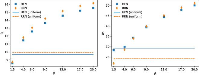
Figure 4. Peak current Ip and work of failure Wf for hierarchical and non-hierarchical systems, as functions of the Weibull shape parameter β. For comparison, results for uniform threshold distributions with the same average are included as horizontal lines. Systems have size Nx = 128. Data for each choice of parameters are averaged over 800 realizations.
Download figure:
Standard image High-resolution image3.2. Crack area statistics
We now investigate the effects of the hierarchical structure on the statistics of interface crack sizes, as a way to quantify the observation of distributed damage and relate it to the degree of interface disorder. Figure 5 shows the dependency of the areas of the two largest cracks, give in units of system size, on the fraction of removed edges (damage fraction). We first discuss the behavior of the RRN seen in figure 5 (right). Here we observe see two qualitatively different types of behavior: at low disorder (threshold distributions with β = 4 and β = 9), we see a nucleation-and-growth scenario where the behavior of the system is entirely dominated by the largest crack. After a short initial interval of diffuse damage accumulation which becomes shorter with decreasing disorder, the largest crack becomes critical and its growth attracts all the newly failing edges, leading to a linear dependency of the largest crack size s1 on the failed-edge fraction. At the same time, the size s2 of the second largest crack is, in comparison, negligible. At high disorder (β = 1.5 and uniform threshold distribution), on the other hand, we find a percolation-like scenario where, at a critical damage fraction, the size s1 of the largest crack increases rapidly while the size s2 of the second-largest crack reaches a maximum (i.e. it first increases, then decreases because of coalescence with the largest crack).

Figure 5. Largest (s1) and second largest (s2) crack areas, as a function of the fraction of removed edges. Areas are measured in units of the cross-section surface area, so that they take values between 0 and 1. For each choice of parameters, results are averaged over 800 realizations. Larger values of s2 point to broader distributions of crack areas. In the weak disorder limit (thicker lines) hierarchical systems preserve broad distributions of crack areas, where non-hierarchical systems fail by nucleation of one giant crack.
Download figure:
Standard image High-resolution imageIn HFN, on the other side, the nucleation-and-growth scenario is entirely absent. Here we see for all degrees of disorder a percolation-like scenario: the largest crack exhibits nonlinear growth behavior where an acceleration of growth coincides with a peak in the size of the second-largest crack.
We next investigate how the different behavior of HFN and RRN is reflected in the crack size distributions and their evolution. At high disorder (β = 1.5 and uniform distribution), differences in crack area statistics of HFN and RRN appear to be minor. Both types of structures seem to follow a critical-like scenario where the crack size distribution is well described by equation (4) with crack size exponent τ = 2 and 1/σ ≈ 1.4...1.7. In the systems showing appreciable post-peak activity (HFN and RRN with β = 1.5), the scale-free distribution persists without discernible cut-off into the post-peak regime. This is illustrated in figures 6 and 7, which also show typical damage patterns immediately past the peak load.

Figure 6. Distributions of crack areas for increasing values of the applied voltage, for uniform threshold distributions. Data here and in the following are from the same simulations as in figure 5. Interface spanning cracks, when they appear, are outliers and are not represented in these distributions. Below the peak load, hierarchical and non-hierarchical systems exhibit comparable truncated power law distributions. Distributions below the peak load can be fitted (solid lines) by equation (4) with τ ≈ 2, and 1/σ ≈ 1.7. Post-peak distribution for the HFN case is a power-law with exponent τ ≈ 2 without a visible cutoff. The bottom row of the figures shows typical damage patterns immediately after the peak load, indicating diffuse damage accumulation for the HFN and critical crack growth for the RRN.
Download figure:
Standard image High-resolution image
Figure 7. Distributions of crack areas for increasing values of the applied voltage, for β = 1.5. Below peak load, both systems exhibit truncated power laws as crack area distributions, with τ ≈ 2 and 1/σ ≈ 1.8 (HFN), 1/σ ≈ 1.4 (RRN). Both systems display post-peak activity in V-control, where crack area distributions are power laws of exponent τ ≈ 2. The damage patterns indicate diffuse damage accumulation both in HFN and in RRN (bottom row).
Download figure:
Standard image High-resolution imageThe main difference between the uniform and the β = 1.5 Weibull distributions shows in the post-peak regime. In this regime, the damage patterns and crack size distributions in HFN are insensitive to the threshold distribution, whereas the failure mode of RRN depends on the high-strength tail of the threshold distribution. For a uniform distribution, there is a maximum strength and the failure mode of RRN is by crack nucleation-and-growth. For a Weibull distribution of low exponent, on the other hand, fuses with high local failure thresholds in the distribution tail act as pins that promote crack arrest, and failure therefore proceeds by diffuse damage accumulation. We see that this behavior has, despite the apparent similarities, different causes in RRN and HFN: in the non hierarchical structures, crack arrest is dependent on the strength tail asymptotics, whereas in the hierarchical networks it represents a generic structural feature that does not depend at all on the statistics of local strength.
As expected from connected components analysis, the behavior of HFN in the low disorder limit differs strongly from their RRN counterparts (figures 8 and 9). RRN display extremely narrow crack area distributions, in agreement with the expectation of failure by crack nucleation-and-growth. The behavior in the approach to failure can be fitted by equation (4) but the scaling regimes are very limited and the distributions approach pure exponentials. HFN, instead, seem to induce scale free fracture patterns even below the peak load. These self similar patterns appear as power-law crack area distributions with continuously varying exponents that decrease towards the peak load—a behavior also observed in bulk failure of HFN [9]. While the system does possess structural network heterogeneity in the bulk, the interface initially has no structural heterogeneity and very low fluctuations in the local thresholds. The fact that broad distributions of crack areas emerge regardless thus points to a novel mechanism where crack patterns are mediated exclusively by the mechanism of stress redistribution in the bulk.

Figure 8. Distributions of crack areas for increasing values of the applied voltage, for β = 4. HFN display power-law crack area distributions at all loads, with exponents that decrease towards peak load. The limiting distribution at peak load is characterized by an exponent τ ≈ 2.8. Damage profiles show the absence of a critical growing crack. RRN display very narrow area distributions, where truncated power-laws are dominated by exponential tails. A fit with equation (4) indicates τ ≈ 3, 1/σ ≈ 1.
Download figure:
Standard image High-resolution image
Figure 9. Distributions of crack areas for increasing values of the applied voltage, for β = 9. In analogy with the case of β = 4, HFN display generic power-law crack area distributions even before peak load. The limiting distribution at peak load is characterized by an exponent τ ≈ 2.6. RRN display very narrow area distributions, with τ ≈ 3.6, 1/σ ≈ 1.
Download figure:
Standard image High-resolution image
4. Discussion
While motivated by the observation of multi-level structural patterns in the adhesion of certain biological materials, interface failure of hierarchical materials may provide important insights into the design of engineered structures with properties of enhanced adhesion. Our results show that from the point of view of the work of failure, i.e. the amount of work necessary to detach a model material from a substrate, hierarchical structures offer obvious advantages in the limit of high interface heterogeneity. While the failure mode of hierarchical materials normally becomes advantageous in the presence of pre-existing cracks, here we note that the higher work of failure at high surface heterogeneity is independent of the presence of embedded damage.
Our findings on non hierarchical systems confirm, for the case of interface failure, the generic observation that such systems depending on the degree of disorder exhibit two qualitatively different failure scenarios. At high disorder, crack nucleation is facilitated but crack propagation is inhibited, and thus failure occurs in a percolation-like manner by diffuse nucleation and coalescence of small cracks. In this regime, the effects of hierarchical organization are minor. The behavior of both RRN and HFN under increased loading is well described by a critical-like scenario where a correlation length (the cut-off crack radius) diverges at the peak stress, i.e. at the point of failure. At low disorder, non hierarchical systems fail by nucleation-and-growth of a critical crack. In this regime, the behavior of hierarchical systems is quite different and matches observations in failure of hierarchical bulk systems.
The ability of hierarchical systems to inhibit crack propagation and promote diffuse damage accumulation is robust and does not depend on the degree of disorder. At low disorder, hierarchical structure leads to self similar damage patterns even below the peak load: the crack size distributions represent power laws without discernible cut-off, and the main effect of increasing load is to decrease the power law exponent, thus shifting the mean crack size to larger values. We note that early evidence of scale-free fracture patterns in hierarchical models of adhesion was found under the assumption of active material response, as a model mechanism for adhesion/detachment switching for gecko pads [22]. Our results confirm that the same picture extends also to the much more general scenario of non-active response, and is for the most part insensitive to the degree of interface heterogeneity.
Previous studies of fracture in thin-film geometries have shown that sample thickness affects the form of the elastic kernel in non-hierarchical systems [33]. In that case, film thickness is found to introduce a characteristic length scale, which effectively cuts off long-range elastic interactions along planar crack fronts. While in our case elastic interactions are controlled by the hierarchical geometry and its self-similar structure, the interplay of network topology and sample thickness might indeed be responsible for additional cut-off lengths, which might play a role for instance in the case of high heterogeneity, where the difference between hierarchical and non-hierarchical system response below the peak load is minimal. The study of the effect of varying sample thickness is being considered for future work.
Our modeling approach relies on several simplifying assumptions. While these assumptions are appropriate for a proof-of-concept study like the one proposed here, they must be kept in mind when considering applications to materials interface design. First, the RFM approach represents a caricature of the elastic problem, where loads and displacements are reduced to scalars and even the distinction between shear and tension/compression is not possible. While fuse models correctly describe the elastic response of a system in an anti-plane shear geometry, their application to the general problem of interface failure is of course an approximation [18]. This limitation can be easily remedied by adopting a beam-model description, although at the price of more computationally intensive simulations [11]. Second, the quasi-static simulation protocol effectively ignores the aspects of dynamics, whereas a proper dynamic simulation would allow one to investigate interesting phenomena such as detachment fronts. Third, the deterministic hierarchical network construction is an idealization of a hierarchically patterned interface, which was chosen for the sake of simplicity. The generalization to randomized hierarchical structures is straightforward, as previously shown for problems of bulk fracture [9]. Fourth, our failure criterion extends only to the system interface. A more realistic implementation would also allow for failure in the bulk, ideally with a distinct threshold distribution that encodes heterogeneity in the material, rather than at the interface. We notice that, while these assumptions are a limiting factor in applications, more realistic implementations are, in all cases, straightforward. Our results, and future refinements addressing the limitations pointed out above, should be instrumental to the design of fault-tolerant interface geometries, where adhesion properties are tunable and crack propagation is arrested.
In conclusion, we have presented a proof-of-concept model for interface failure of hierarchical materials in contact with surfaces of varying degrees of heterogeneity. Our results show that hierarchical patterning always allows for a fracture mode that inhibits crack propagation and favors distributed damage. In addition to this property, the hierarchical structure also interacts with the interface heterogeneity in remarkable ways. At high interface disorder, it delays detachment, by introducing a novel post-peak regime, which effectively increases the work of failure. At low interface disorder, it allows for redistribution of failure across the entire system, in spite of the otherwise highly homogeneous interface.
Author contributions statement
N E carried out the simulations, analyzed the data and drafted the manuscript together with P M. M Z provided input on data analysis and edited the manuscript. All authors reviewed and approved the final manuscript.
Acknowledgments
The authors acknowledge support by DFG, through Grant GRK 2423 FRASCAL.