


Abstract
Experiments on the DIII-D tokamak demonstrate that edge localized mode (ELM) stability can be manipulated using localized electron cyclotron current drive (ECCD) in conjunction with resonant magnetic perturbations (RMPs). The injection of counter-plasma-current edge ECCD reduces the RMP amplitude required to suppress ELMs and bifurcates the pedestal into a high-confinement regime with 7 kPA pedestal pressure. This is the first time such a high confinement regime has been accessed through the bifurcation from the ballooning stability branch predicted by existing models. These observations are consistent with modeled ECCD manipulation of magnetic islands induced by the RMPs.
Export citation and abstract BibTeX RIS

Original content from this work may be used under the terms of the Creative Commons Attribution 4.0 license. Any further distribution of this work must maintain attribution to the author(s) and the title of the work, journal citation and DOI.
1. Motivation
The tokamak, a toroidally axisymmetric device, is the leading candidate for magnetic confinement of a burning plasma for fusion energy production. High confinement regimes (H modes [1]) on the tokamak are envisioned candidates for future fusion reactors but create a challenging environment for plasma facing components. These components are compromised by edge localized mode (ELM) instabilities [2, 3] at the H mode edge transport barrier (called the pedestal), which eject plasma to the wall. One method for preserving reactor walls by stabilizing these ELMs is to break the axisymmetry of the tokamak with small resonant magnetic perturbations (RMPs [4, 5],  ) to open magnetic islands at the top of the pedestal that limit the pedestal pressure [6–9]. An unfortunate side effect of RMP ELM suppression is an associated density degradation that is due to pedestal foot islands and neoclassical transport induced by the broad poloidal spectrum of the coils used [10, 11] and much effort is being spent to minimize this degradation through complex control techniques in order to maximize fusion efficiency [12]. Even at its most optimized, however, this approach of RMP ELM suppression requires enough degradation in the pedestal height/width to keep it from the peeling–ballooning (PB) stability limit. The PB model is widely accepted for describing tokamak edge stability in H mode. It posits that peeling modes, driven by the edge bootstrap current, and ballooning modes, driven by the edge pressure gradient, couple in the pedestal region and set a magnetohydrodynamic (MHD) stability limit, beyond which ELMs are triggered [13].
In this work, we show that localized current drive in the tokamak edge plasma can be used to decrease or increase the level of RMPs required to suppress ELMs. Section 2 shows how localized electron cyclotron current drive (ECCD) manipulates the width of the pedestal while the associated electron cyclotron (EC) heating (ECH) raises the pedestal temperature. This combination has enabled experimental validation of a predicted bifurcation from peeling limited pedestal pressures to a channel of stability with super high (SH) confinement. Further experimental scans of the EC deposition clarify the critical role of the current drive, in particular. Section 3 shows the experimental results are consistent with the modeled interaction between this local current drive and small magnetic islands at the edge of the plasma, lending confidence that the benefits of combined RMP and ECCD can be extrapolate to future experiments and devices. The primary conclusions to be drawn from this novel combination of actuators and critical implications are summarized in section 5.
2. Experimental results combining RMPs and edge localized current drive
Experiments applied combinations of n = 3 RMPs and EC waves to the edge of DIII-D plasmas [14]. Here, n is the toroidal mode number of the applied RMPs. All plasma discharges were lower single null 'ITER-Similar Shape' with upper (lower) triangularity of 0.35 (0.70), plasma current  MA, toroidal field on axis
  T, and an edge safety factor
  . The pre-programmed neutral beams injected powers of 6.3–7 MW, which produced normalized pressures of
  . ECCD was injected into the top outer edge of the plasmas, as shown in figure 1.
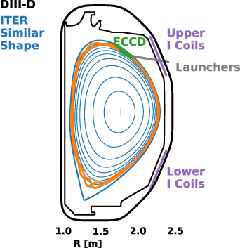
Figure 1. Poloidal cross section of the DIII-D vessel (black), ITER similar shape plasma last closed flux surface (thick blue), n = 3 resonant surfaces (light blue), upper and lower I coils (purple) and edge ECCD injection location (green). The  island separatrix from TM1 modeling of 4.0 kA n = 3 RMPs is shown in orange.
Download figure:
Standard image High-resolution imageThe RMP threshold for ELM suppression in this scenario was established by slowly ramping up the n = 3 RMP amplitude, as shown by the blue traces in figure 2. The RMP is produced using in-phase n = 3 currents in the upper and lower internal coil arrays (I coils [15], shown in blue in figure 1). This discharge exhibited standard RMP ELM suppression behavior. The edge resonant field penetrated at 3.0 kA (2.75 s), causing a drop in pedestal pressure and bringing an end to the large type-I ELMs. Mitigated ELMs persist for 0.1 s before giving way to complete suppression at 3.2 kA. During the suppression phase, the pedestal pressure remains below the PB limit (other than a transient caused by the influx of a large dust granule). When the RMP amplitude is ramped down, the pedestal pressure rises until ELMs return as predicted at the PB boundary (not shown).
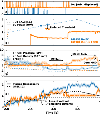
Figure 2. ELM bursts are suppressed (a) during the application of large RMPs ((b), blue) or smaller RMPs and counter-Ip ECCD ((b), orange). The pedestal pressure (c) is much higher while the magnetic response ((d): measured in solid, modeled in dashed lines) remains lower in the ECCD assisted case. The ECCD case has pedestal pressures well above the EPED neural net predicted stability boundary ((c), bold lines).
Download figure:
Standard image High-resolution imageExperiments then revealed that counter-Ip edge localized current drive can decrease the RMP ELM suppression threshold and access SH confinement while maintaining ELM suppression. The RMP was fixed below the established 3.0 kA threshold and progressively larger amounts of ECCD were injected. The ECCD steps of 1.2, 2.2, and 3.5 MW correspond to 3.0, 6.0, and 9.0 kA of counter-Ip driven current, respectively. Note, this amount of ECCD is only 0.17%–0.53% of the plasma current and comparable to the noise in the total Ip prior to any ECCD injection. Figure 2 shows the EC assisted RMP ELM suppression, enabling ELM suppression at 0.5 kA (17%) below the 3.0 kA RMP penetration threshold (triangle) and 0.7 kA (22%) below the suppression threshold (star). The 0.5 s of RMP without ECCD confirmed that the large type-I ELMs continue to regularly go unstable. With the application of 3.0 kA ECCD, the ELMs continued for 0.4 s before transitioning directly to a suppressed state. No transition period of mitigated ELMs was observed in this case. Like the RMP-only suppression, a drop in the pedestal pressure and jump in the measured n = 3 plasma response was observed. The plasma then stayed in a robust ELM suppressed state for 0.4 s before a slow, global rise in the temperature results in a higher pedestal pressure and a few ELMs. These were quickly re-suppressed by the stepped increase of ECCD to 6.0 kA (2.2 MW). A separate discharge (169959, not shown) with 3.0 MW of counter-Ip ECCD injected during a 2.0 kA RMP (33% below the RMP-only threshold) pulse exhibited similar behavior and obtained a 0.25 s window of suppression prior to the return of sparse ELMs, indicating the potential for further reductions in the RMP threshold with this new actuator.
At the higher EC power, robust ELM suppression is obtained with high pedestal pressures well above the PB stability limit predicted by a EPED neural net [16, 17]. This is a stably suppressed state with the pedestal pressure rising due to a gradual rise in temperature, not the runaway rise in density of an ELM-free state (both discharges have a steady pedestal density of  m−3 during this time). The 7 kPa electron pedestal pressure obtained during this time exceeds the highest RMP suppressed pedestal pressures previously reported by nearly 40% [18].
The ECCD and associated ECH maintained stability by accessing a channel of stability at high pressure. Figure 3 shows that while the EC induces some particle pump out, the ECH associated with the counter-Ip
ECCD in this case significantly raised the pedestal electron temperature and, in turn, the ion temperature. The result was a reshaping of the PB stability boundary calculated by ELITE (figure 3(a) shows the boundary of  , where γ is the growth rate,
  is the diamagnetic frequency and
  is the diamagnetic stabilization). The region above and to the right of this boundary is unstable [13]. The boundary moved down in normalized current,
  , and out in normalized pressure gradient. In the process, the plasma moved from the ballooning boundary (purple) to near the peeling boundary (gold). Figure 3(b) shows that these pedestals were initially limited by the EPED ballooning boundary (lower black line), evolved down in pedestal density when ECCD was first applied, and then bifurcated to a high pedestal pressure state below the peeling boundary. The black lines of figure 3(b) represent the standard EPED boundary. The red lines indicate the boundary of a second stability found at fixed pedestal density in the model, known as the super H-mode channel [19, 20]. The data shown in figure 3(b) uses twice the electron pedestal pressure to estimate the total pedestal pressure for comparison to the EPED boundary and a measured
  despite the model's
  . The initial evolution down in density with the application of ECCD is consistent with the ubiquitous occurrence of EC particle pump out in DIII-D and only slightly accelerated by the bifurcation at 2.9 s (orange triangle, figure 2(b)). The bifurcation to high pressure is the critical experimental result and the existence of the SH channel is the critical model result. This bifurcation has been predicted in the model of SH mode confinement [19, 21], but this uniquely favorable regime has hitherto been accessed from the peeling branch. This represents the first known SH mode access through the predicted bifurcation from the ballooning branch.

Figure 3. The ECCD-RMP ELM suppressed discharge 169981 moved from the ballooning to near the peeling boundary predicted by ELITE (a), bifurcating into a SH channel with high pressure (b). ECCD was accompanied by electron (c) and ion (d) heating that overcame the density pump out (e) to raise the pressure (f). The measured carbon temperature (d) is assumed to be equilibrated with the main deuterium ion temperature.
Download figure:
Standard image High-resolution imageThe pedestal pressure eventually rolled over at 3.9 s due to the appearance of thermal ion driven kinetic ballooning modes in the core that decreased the global confinement over a 0.05 s timescale [22]. These modes are a consequence of the high core ion temperatures (10–15 keV), and appeared when the q = 1 surface entered the plasma. Without this core instability, there is no indication that the record ELM-suppressed pedestal pressure could not be maintained.
To further investigate the impact of EC waves on RMP ELM suppression, the waves were also injected into already RMP ELM suppressed plasmas as shown in figure 4. First, 4.0 kA n = 3 RMPs were applied. The RMP-induced particle and heat transport was sufficient to reduce the pedestal pressure below the EPED calculated PB stability boundary and the ELMs were suppressed as seen by the lack of Dα spikes (figure 4(b)). EC waves were injected at 3.2 s (figure 4(a)) and the EC power increased further at 4.0 s. In three plasma discharges, the EC steering was adjusted such that waves drove co-Ip , counter-Ip , or no (heating only, ECH) current in the pedestal.

Figure 4. Experiments comparing the impact of EC wave injection angle on the ELM stability show the Counter-Ip ECCD (blue) and ECH (orange) injection (a) recover high pedestal pressures (c) without ELMs (b), while co-Ip ECCD (green) destabilizes ELMs.
Download figure:
Standard image High-resolution imageOnly the co-Ip ECCD injection restored ELMs to the RMP suppressed scenario. All three EC configurations heated the pedestal, significantly raising the pedestal pressure as shown in figure 4(c). All three discharges rose to the standard ballooning limits predicted by the EPED [13] model from the global equilibrium quantities (unfortunately, the plasma density was such that these shots stayed to the right of the bifurcation point in figure 3(b). At this pressure, the discharge with co-Ip ECCD began to re-exhibit ELM instabilities. These increased in frequency when the EC power was increased from 1.6 to 2.9 MW at 4.0 s. The ELMs that returned were smaller in amplitude than the large type-I ELMs [23] that existed prior to the RMP and the final plasma exhibited a limit cycle behavior between high frequency ELMing and ELM-free states. Discharges without co-Ip current drive persisted in a robustly ELM suppressed state, recovering 100% of the original H-mode pedestal pressure and returning to near the EPED pedestal pressure stability boundary. The nearly 4.4 kPa electron pedestal pressure obtained in these discharges is comparable to the highest RMP suppressed pedestal pressures previously reported in DIII-D [18].
The return of ELMs is hypothesized to be due to ECCD healing of the pedestal top islands that were limiting the pedestal pressure below the PB boundary. This has parallels with neoclassical tearing mode (NTM) ECCD suppression [24–29]. Unlike core NTM studies, however, these plasmas are naturally stable to tearing modes near the pedestal top where the mode is being driven by an external field term,  [7–9, 30, 31]. Figure 5 shows the level of current drive calculated using the TORAY code [32]. These deposition models utilize axisymmetric equilibrium reconstructions that incorporate the ECCD but do not include the small nonaxisymmtric displacements due to the RMP. For both the co- and counter-Ip
discharges, the local current density is only 10% of the toroidal plasma current, which peaks in the edge due to the bootstrap current. As mentioned previously, the integrated current drive is less than 1% of the total plasma current in all cases. While each discharge has 100% power absorption, the ECH discharge has negligible current drive. In the following paragraphs, we will show the achieved level of co-Ip current drive is sufficient to replace the resonant shielding currents in the pedestal top and remove the island transport that was limiting the pedestal pressure.
[7–9, 30, 31]. Figure 5 shows the level of current drive calculated using the TORAY code [32]. These deposition models utilize axisymmetric equilibrium reconstructions that incorporate the ECCD but do not include the small nonaxisymmtric displacements due to the RMP. For both the co- and counter-Ip
discharges, the local current density is only 10% of the toroidal plasma current, which peaks in the edge due to the bootstrap current. As mentioned previously, the integrated current drive is less than 1% of the total plasma current in all cases. While each discharge has 100% power absorption, the ECH discharge has negligible current drive. In the following paragraphs, we will show the achieved level of co-Ip current drive is sufficient to replace the resonant shielding currents in the pedestal top and remove the island transport that was limiting the pedestal pressure.
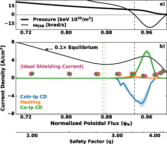
Figure 5. Equilibrium pressure ((a), thick), E × B rotation ((a), thin) create ideal conditions for RMP penetration near the pedestal top where flux surface average parallel EC current drive (b) ten times lower than the equilibrium toroidal current ((b), black) is comparable to the ideal MHD shielding current response (circles). Vertical dashed lines mark  (black) and vacuum island overlap width (green and orange).
Download figure:
Standard image High-resolution image3. Modeling insights explaining the impact of ECCD on RMP suppressed pedestals
Ideal MHD calculations using the Generalized Perturbed Equilibrium Code (GPEC, [33–35]) confirm the linear, resonant plasma response to the applied n = 3 RMP is not meaningfully altered by any axisymmetric profile modifications of the EC current drive versus heating. This can be seen from the fact that the resonant shielding current estimates (circles) are overlapping in figure 5. These current density estimates divide the resonant shielding current (necessary to prevent islands in ideal MHD) on each rational surface by the effective area for an island of width corresponding the full penetration of that current (1.7 cm at the top of the pedestal). The values are comparable to the co-Ip
ECCD current at the  and
and  rational surfaces (m is the poloidal mode number) at the top of the pedestal where the E × B rotation is near zero and islands are expected for RMP ELM suppression [7, 36]. This modeling shows that the island drive from the plasma response,
  , is not altered by the co-Ip
ECCD but that the current is sufficient to replace the 'missing' shielding current and heal the island responsible for ELM suppression.
, is not altered by the co-Ip
ECCD but that the current is sufficient to replace the 'missing' shielding current and heal the island responsible for ELM suppression.
The interaction of local ECCD and RMP induced transport in the pedestal is further elucidated using the TM1 nonlinear MHD code, which has been validated on many DIII-D RMP ELM suppression experiments [8, 10, 37, 38]. Figure 6 shows the model reproduces the experimental observations from discharge 169964, in which co-Ip ECCD restored ELMs. When the 4.0 kA n = 3 RMP is applied at time 0 s, the 11/3 resonant field penetrates and a reasonable size (2% of the minor radius, shown in figure 1) island saturates at the top of the pedestal. When co-Ip ECCD is then applied 0.3 s later, the island is suppressed to as little as one quarter the width (gold and pink traces in (a) and circles in (b)). The application of counter-Ip (purple), in contrast, slightly increases the island width. The ECH associated with each of the three cases is not included in the TM1 modeling here. In each case, a Gaussian approximation of the ECCD radial profile from figure 5 is used to set the initial current source as [39],
where  ,
,  , and
, and  specify the magnitude, the radial full 1/e width, and the deposition location of the source, respectively. Π is a square box function to take into account the wave deposition profile along the helical angle
  , and ξ0 is the center of the ECCD along the helical angle. The ECCD deposition region has an instantaneous deposition width
  along the helical angle of 90∘, corresponding to the 25∘ poloidal extent from TORAY shown in figure 1. Note that while the island was not taken into account in the TORAY calculations, the TM1 model does include a nonlinear broadening of the ECCD deposition that self-consistently decreases the total driven current amplitude in the presence of the island. The extent of the ECCD is such that it is not localized near a single X or O-point of the 11/3 island, and as such the modeling is insensitive to the choice of either ξ0 or
  . Previously validated core NTM studies found that, due to the very fast parallel transport of fast electrons, a helical ECCD current appears inside islands even when the deposition width is larger than the island width [40, 41]. The stabilizing effect of the helical ECCD current is actually stronger for smaller island widths, and it is insensitive to the poloidal harmonic [40].

Figure 6. TM1 modeled time traces (a) show the change in the width (normalized to the minor radius) of a RMP driven island at the pedestal top when −1 (purple), 1 (pink), and 2 (gold) times the experimental level of co-Ip
current drive is applied at 0.3 s in the simulation. A scan of the current drive (b) shows the pedestal pressure is restored to the original value ( ) with the reduction of the island width.
Download figure:
Standard image High-resolution image
The modeling here confirms that the experimental level of edge current drive, comparable to the ideal MHD shielding current, is sufficient to significantly modify the island size and restore the original PB-unstable pedestal. Like the experience with seed NTM suppression, this is despite the applied current being axisymmetric and much wider radially than the island itself. Additional model development is needed to incorporate the effect of local ECH modifications of the island width through the temperature's effect on the background pressure and current profiles.
A mix of global ideal MHD and local resonant-layer bifurcation can also explain the experimental observations in the case of ECCD-assisted RMP ELM suppression. The dotted lines shown in figure 2(d) correspond to synthetic diagnostic measurements taken from GPEC modeling. The synthetic diagnostic reports the n = 3 plasma response averaged over the length of the high field side poloidal field sensors that best correlate with ELM suppression in these plasmas [42, 43]. The modeling uses the linear ideal-MHD plasma response calculation from which the resonant shielding is determined for figure 5. Based on multi-harmonic TM1 ELM suppression modeling experience [10], penetration events are simulated by removing the synthetic measurement contributions from shielding current layers at both the pedestal top (q = 9/3 and 10/3) and foot (q = 13/3) rational surfaces. The initial response has the farthest pedestal-foot (q = 14/3) surface contribution removed, approximating the complete penetration of this surface that is also robust feature of TM1 RMP modeling. The result is a stepped response consistent with the experimentally measured response, as shown in figure 2(d). The surfaces chosen were chosen to match the amplitude of the experimental step response and are consistent with the TM1 penetration modeling experience in these ITER-similar shape plasmas.
This linear and nonlinear MHD modeling is consistent with the fundamental condition for ELM suppression in these plasmas being the existence of a magnetic island at the top of the pedestal. Island penetration leads to ELM suppression in both the RMP-only and ECCD-assisted suppression of figure 2. Modeled ECCD healing of the pedestal top island causes a return of the pressure consistent with the return of the ELMs in figure 4.
4. Unique ELM properties with RMPs and edge localized ECCD
At this point, it must be acknowledged that our understanding does not encompass a self-consistent interplay between the RMP, ECCD and PB stability. Notably, the ELMs observed occurring in the combined presence of RMPs and edge ECCD differ from the natural type I ELMs. The return of ELMs with co-Ip
ECCD (figure 4, 169964) are lower amplitude and higher frequency than the origianl type-I ELMs. This can be seen directly in the  traces shown and holds true for as divertor heat-flux, energy loss and density loss measurements as well. The ELMs that reappear are more similar in size and frequency to grassy ELMs [44, 45] as well as small ELMs sporadically observed during plasma current ramps.
The typical RMP ELM suppression loss precursor of a  baseline dip is not observed in shot 169964 prior to the loss of suppression. These precursors are associated with complete island healing enabling a sudden inhalation of scrape-off layer particles by the growing pedestal [46]. From this, it is inferred that the edge island originally opened by the RMP never fully bifurcates away but is smoothly modulated in size during a limit cycle process. The ECCD island width reduction enables the building of both density and temperature without ELMs until fast, low amplitude ELMs begin and the pedestal pressure then decreases until the ELM stop and the process is repeated. This is expected from the TM1 modeling if, for example, the ECCD deposition location is modified by the changing pedestal profiles. The RMP-only discharge in figure 2 does not exhibit this behavior and immediately returns to regular type-I ELMs when the RMP is reduced below the level needed to sustain suppression.
The new small ELM instabilities in the presence of RMP and edge ECCD are worth more theoretical attention in the future. Three dimensional, kinetic ballooning stability calculations, the model for which is described in in detail by [47], show there is no significant change in the ballooning stability between the ECCD and ECH cases or between 2D and the 3D equilibrium taking into account the ideal plasma response. Instead of influencing the ballooning stability through the magnetic shear, the ECCD  driven through and around the island region may be directly influencing the peeling stability. Although the development of a fully 3D peeling model is beyond the scope of this initial letter, these results serve as foundational motivation for such model development in order to better predict and optimize the edge ECCD influence on ELM stability.
5. Conclusions
New experiments have shown that RMP ELM suppression and the fundamental nature of the pedestal stability can be manipulated using ECCD localized near the edge. Counter-Ip ECCD and/or ECH can be used to fully recover from the pedestal pressure reduction associated with RMP ELM control while maintaining a suppressed state. This recovery of the RMP pedestal pressure degradation previously associated with robust ELM suppression clearly demonstrates the exciting potential for edge localized ECCD as an important new actuator in tokamak edge stability control.
Co-Ip ECCD of levels comparable to the shielding current required to maintain concentric flux surfaces in the presence of the RMP return ELM instabilities. This is consistent with nonlinear MHD modeling of the RMP opening islands at the top of the pedestal and the impact of ECCD on those island widths. For the predicted RMP ELM suppression currents for the ITER 15 MA baseline scenario [9], the corresponding shielding currents are less than 0.5% of the plasma current. The ITER gyrotrons are unfortunately not designed for edge aiming, but if they were then the gyrotron power needed for such current drive would be comparable to existing power planned for NTM suppression. The associated physics has important implications for the stabilization of error field induced tearing modes in the plasma core as well, suggesting a modest investment in local current drive could significantly alleviate coil symmetry tolerance requirements.
Counter-Ip edge ECCD is capable of assisting RMP ELM suppression, reducing the critical threshold for suppression and enabling significantly higher pedestal pressures during suppression by raising the temperature and accessing a SH mode stability channel above the standard EPED limit. ELM suppressed operation in the SH channel is held for multiple energy confinement times, suggesting robust operation in this regime is possible if the core instabilities experienced in this particular plasma scenario are avoided.
The DIII-D ECCD system was not designed or optimized for edge current drive, but it is flexible aiming has enables this novel application. Development of similar capabilities on other tokamaks and/or more efficient edge localized current drive on DIII-D would go a long way towards enabling further investigation the interplay between RMP and ECCD. While further experimental investigations are needed to optimize and assess the impact of edge localized current drive on the global performance of SH and H-mode RMP ELM-suppressed plasmas, this work establishes an important new actuator combination for optimizing tokamak pedestal pressure while maintaining ELM suppression.
Acknowledgments
This work was supported by the U.S. Department of Energy, Office of Science, Office of Fusion Energy Sciences, using the DIII-D National Fusion Facility, a DOE Office of Science user facility, under Awards DE-AC52-07NA27344, DE-AC02-09CH11466, DE-AC05-00OR22725, DE-FC02-04ER54698, and DE-SC0022270. Experiments were allocated through the Torkil Jensen award program.
Disclaimer
This report was prepared as an account of work sponsored by an agency of the United States Government. Neither the United States Government nor any agency thereof, nor any of their employees, makes any warranty, express or implied, or assumes any legal liability or responsibility for the accuracy, completeness, or usefulness of any information, apparatus, product, or process disclosed, or represents that its use would not infringe privately owned rights. Reference herein to any specific commercial product, process, or service by trade name, trademark, manufacturer, or otherwise does not necessarily constitute or imply its endorsement, recommendation, or favoring by the United States Government or any agency thereof. The views and opinions of authors expressed herein do not necessarily state or reflect those of the United States Government or any agency thereof.