


Abstract
We report the first preemptive direct stabilization of  neoclassical tearing modes (NTMs) in DIII-D low-torque ITER baseline scenario plasmas by electron cyclotron waves. These experiments strongly support that the observed stabilization is achieved by replacing the missing bootstrap current in the island by electron cyclotron current drive (ECCD). These plasmas (with and without ECCD) are stable to 2,1 NTMs when the differential rotation between the q = 1 and q = 2 surfaces (
 ) is sustained above a critical value (
 kHz), but those evolving to low differential rotation (
 ) routinely develop a disruptive 2,1 island at the time and frequency of a sawtooth precursor. Preemptive, local and direct stabilization by ECCD is tested by scanning the current drive amplitude and location inside and outside of the q = 2 rational surface shot by shot. Analysis of only low differential rotation time windows, i.e. when stabilization from
  is absent, shows focused ECCD at q = 2 prevents the onset of 2,1 NTMs. These results are important, as they give the first demonstration of disruptive NTM control by ECCD in the plasma scenario planned for ITER.
Export citation and abstract BibTeX RIS

Original content from this work may be used under the terms of the Creative Commons Attribution 4.0 license. Any further distribution of this work must maintain attribution to the author(s) and the title of the work, journal citation and DOI.
1. Introduction
Tearing modes are resistive magnetohydrodynamic instabilitie tokamak plasmas [1]. Due to the fast parallel transport along the field lines, the pressure profile flattens within the magnetic islands [2–6]. This leads to a helical perturbation of the pressure gradient driven bootstrap current ( ), which reinforces the island growth [7–9]. Neoclassical tearing modes (NTMs) are tearing modes that are dominantly
  driven.
  NTMs degrade the confinement [10] and are the most common single root cause of tokamak disruptions [11] (m and n are the poloidal and toroidal mode numbers), which makes their avoidance and active stabilization critically important tasks for scenario development of present day experiments and for operational regimes of future fusion reactors. Local electron cyclotron current drive (ECCD) may be used to replace
  , which can therefore stabilize NTMs [12–18]. In addition, due to the nested flux surface topology and reduced cross-field diffusivity within the island, EC heating alone produces a temperature perturbation in the island [19–22], which may also modify the local resistivity and thus the ohmic current to partially compensate for the missing bootstrap current. On the other hand, preemptively driven ECCD may prevent 2,1 seed islands from surpassing the threshold for neoclassical growth and thereby avoid the growth of large 2,1 islands and concomitant disruptions. However, the effect of the EC heating on the resistivity alone is not expected to prevent the onset of NTMs as it only becomes effective once the island has grown to a large enough size to produce a peaked temperature perturbation in response to the localized heating [23].
The ECCD stabilization approach has become a well documented experimental method in many present day tokamak experiments demonstrating the direct and local effect of ECCD on tearing modes in different variations of high-performance-mode (H-mode) scenarios [19, 24–33]. In the past two decades, a number of developmental tasks have been undertaken at DIII-D to advance the art of tearing stabilization by ECCD. Control algorithms in the DIII-D plasma control system have demonstrated successful real-time alignment of 3,2 and 2,1 islands separately with the ECCD current deposition location, allowing full suppression of tearing modes [34, 35]. Suppression of the 2,1 NTM was demonstrated by ramping the toroidal field to move the ECCD location until it overlapped with the q = 2 surface in a standard H-mode plasma [36]. Preemptive stabilization of the 3,2 island was demonstrated allowing stable long pulse operation in plasmas prone to 3,2 islands [37]. Next, the ECCD was modulated in synchronization with the O-point which allowed tearing control with less net EC power [38]. The development continued by real time mirror steering as an actuator for alignment control [29, 39]. In more recent years, locked island stabilization was also reported [30]. Despite the long history and broad development of the ECCD technique in DIII-D, the stabilization of 2,1 islands in the low-torque ITER baseline scenario [40, 41] has never been reported. This is an important next step since ECCD is the leading candidate to stabilize NTMs in reactors, including ITER [42, 43], which will be equipped with ECCD NTM suppression capability [44, 45].
In this paper we report the first preemptive, direct avoidance of rotating  NTMs by ECCD in DIII-D plasmas [46] using the ITER baseline scenario normalized parameters and shape at low-torque (
 Nm). With and without the application of ECCD, these plasmas are stable to 2,1 NTMs (i.e. passively stable) when the differential rotation between the q = 1 and q = 2 surfaces (
 ) is sustained above a critical value of
  kHz (q is the safety factor). Those plasmas evolving to
  routinely develop a disruptive 2,1 island at the time and frequency of an
  sawtooth precursor when the ECCD is not aligned with the q = 2 surface. In agreement, the rotation has been long known to be important for NTM stability [47–50]. Therefore, plasmas that reach
  provide a testbed for evaluating the efficacy of ECCD in NTM avoidance in low-torque DIII-D ITER baseline scenario plasmas. In this paper we report tests of preemptive, local and direct stabilization of
  NTMs by ECCD by scanning the current drive amplitude and location inside and outside of the q = 2 rational surface shot by shot. Analyzing time-points of
  , i.e. when the instability could occur, the ECCD is shown to prevent the onset of rotating 2,1 NTMs provided that the electron cyclotron beam overlaps with the q = 2 rational surface. These results are important, as they give the first demonstration of disruptive NTM control by ECCD in the plasma scenario planned for ITER.
The rest of the paper is organized as follows. Section 2 describes the discharge parameters and the ECCD aiming scheme. This is followed by the analysis of  tearing onset conditions in section 3. The ECCD stabilization analysis is presented in section 4 and modeling in section 5. Finally, the discussion and summary is given in section 6.
2. Discharge parameters and aiming
We analyze a group of 17 DIII-D ITER baseline scenario discharges. These plasmas are selected from a dedicated experiment testing direct preemptive stabilization of the 2,1 NTM (referred to as 'first set'). A few additional shots are complementing this set by a follow-up experiment (referred to as 'second set'). Two examples are shown in figure 1, one with and one without ECCD [figure 1(e)]. In the shot with ECCD in figure 1, the ECCD density is about twice the local bootstrap current density and it is driven at q = 2. The relevant parameters include  = 1.35–1.375 MA plasma current [figure 1(a)],
  T toroidal magnetic field (in the opposite direction of the plasma current), saturated normalized internal inductance
  [figure 1(b)],
  = 3.75–4.75 MW neutral beam power [figure 1(c)],
  Nm neutral beam torque [figure 1(d)], normalized plasma beta
  [figure 1(f)] (
 ) and maximum line integrated electron density (interferometry [51])
  [figure 1(g)]. The 2,1 magnetic islands are identified from the n = 1 magnetic root-mean-square signal [figure 1(h)]. This analysis [52] uses toroidally (poloidally) separated Mirnov-probes to determine the toroidal (poloidal) mode number of the tearing instabilities. The H-mode confinement enhancement factor (
 ) is about 1.05 (0.9) in the discharge without (with) ECCD [figure 1(i)]. The plasma shape [figure 2(a)] is characterized by lower single null configuration,
  m minor radius,
  m magnetic axis major radius, κ ≈ 1.85 elongation and
  triangularity. The q = 2 rational surface is at ρ ≈ 0.75–0.8 (ρ is the square root of the normalized toroidal flux surface label). The edge safety factor is
  . With the goal to test the efficiency of direct preemptive stabilization of 2,1 NTMs by ECCD, the driven current (
 ) and its location (ρECCD) were varied shot by shot. The current drive location, aiming geometry and deposited power were held constant within each shot. The ECCD amplitude and location is calculated with the GA-Toray ray tracing code [53] using magnetic equilibrium reconstructions constrained by internal Motional Stark Effect data [54], and density and temperature measurements (Thomson scattering [55]) without taking into account the helical structure of the islands.
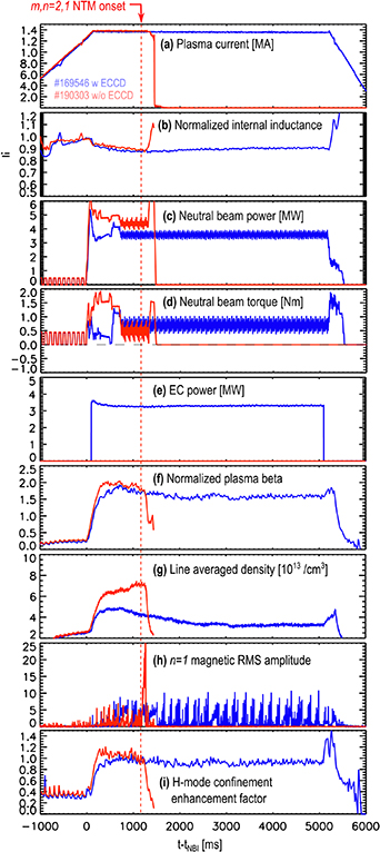
Figure 1. (a) Plasma current ( ), (b) normalized internal inductance (
 ), (c) neutral beam power (
 , (d) neutral beam torque (
 ), (e) electron cyclotron heating power (
 ), ( f) normalized plasma beta (βN), (g) line integrated electron density (
 ) and (h) n = 1 magnetic root-mean-square amplitude (
 ), (i) H-mode confinement enhancement factor (
 ).
).
Download figure:
Standard image High-resolution image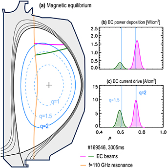
Figure 2. (a) Magnetic equilibrium shape, relevant rational surfaces, the second harmonic electron cyclotron resonance line and the externally driven electron cyclotron beam trajectories. (b) Electron cyclotron power deposition and (c) current drive profiles.
Download figure:
Standard image High-resolution imageExamples of deposited heat and current drive profiles are shown in figures 2(b) and (c), respectively. In the first set of experiments, the wall conditions lead to high density, which could have prevented access to q = 2 by the ECCD. In order to enable access one gyrotron was aimed at ρ ≈ 0.6 (q ≈ 1.5) starting prior to H-mode. This kept the density at a safe level throughout the discharge by leveraging the density pump-out effect of this beam and thereby enabling the rest of the beams to be deposited at the desired location. In the example shown in figure 2 the beam at ρ ≈ 0.6 drove about 6.55 kA ECCD and deposited about 0.5 MW heat. The rest of the 5 EC beams were focused at  (where the safety factor is q = 2), they drove about 12.9 kA ECCD and deposited about 2.5 MW heat. The maximum ECCD is about
  , which is about twice the local bootstrap current density (
 , calculated by the AutoOneTwo transport code based on measured equilibrium and kinetic profiles entered into the Sauter bootstrap current model [56]). The current drive position is scanned in the radial range defined by
  , where
  is the full width half maximum of the Gaussian EC beam (sum of the individual beams). This provides measurements with various degree of overlap between the q = 2 surface and the EC beam between the maximum and zero, including cases with partial overlap on both sides of the surface.
In the second set of experiments, the wall conditions led to favorable density allowing access of q = 2 and beyond without using a fixed EC beam at ρ = 0.6. In this case, 4 gyrotrons were available and they were moved together shot-by-shot delivering 2.3 MW power. The driven current was about 9.7 kA when all the EC beams were centered at q = 2, corresponding to about half the local  . Finally, to test the effect of the EC heating alone without current drive, one additional discharge is included in the analysis with near perpendicular EC beam trajectory to the q = 2 surface (173 643). In this case 1.1 MW EC heating was used which is about half the lowest power at which stabilization by ECCD is observed in this study.
3. Key parameter selection: the role of differential rotation in 2,1 tearing onset in low-torque ITER baseline scenario plasmas
These plasmas commonly develop one or more non-disruptive core islands with n > 1 and  mode numbers which rotationally couple, phase-lock and flatten the rotation profile preceding the onset of the
  island as first reported in experiments [57] and explained theoretically [58]. Subsequent experimental work lead to the observation of disruptive NTM seeding by 3-wave coupling in the low-torque ITER baseline scenario in DIII-D [59]. In most of these plasmas the sawtooth instability is nearly periodic and is characterized by nearly uniform amplitude. Examples of steep and flat rotation profiles before and at the time of onset, respectively, are shown in figure 3(a) (charge exchange recombination, CER [60]). The
  tearing onset occurs at the time and frequency of a sawtooth precursor when
  approaches zero. This suggest that
  has a stabilizing effect on the driven 2,1 seed islands [59], possibly through ion polarization currents [61–64] and screening [65] the sawtooth magnetic perturbation at the 2,1 rational surface. The 2,1 islands, once destabilized, rapidly grow to 25 G or more and terminate the H-mode confinement [figure 1(h)]. In plasmas with intermittent sawtooth activity (not shown) the n = 1 perturbations can grow to significantly larger amplitude which may seed 2,1 islands at
  kHz.
kHz.
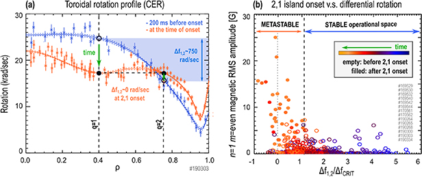
Figure 3. (a) Toroidal rotation at the time of the 2,1 NTM onset (orange) and 200 ms before the onset (blue) in a representative unstable plasma. Black dots highlight the rotation at the q = 1 and q = 2 rational surfaces at onset (filled) and 200 ms before onset (empty). The 2,1 NTM destabilizes when  approaches zero. (b) n = 1,
  magnetic root-mean-square (RMS) amplitude as a function of normalized differential rotation in a group of unstable low-torque IBS plasmas.
  falls in the range of 0.5–1.5 kHz. Coloring indicates the time between the start and the end of the
  flattop.
Download figure:
Standard image High-resolution imageFigure 3(b) depicts the growth of the  islands vs.
  in all unstable discharges of our database. This includes shots with and without ECCD. The open (filled) circles represent time-slices prior to (after) the instability onset. The points with
  are all open, i.e. the plasmas are stable at sufficiently high differential rotation. When
  drops below
  , the plasma is metastable until the next sawtooth occurs. This allows the plasma to stay at
  for a limited time before the 2,1 NTM is destabilized, which is comparable to the sawtooth period. The average time these plasmas spent at
  before the 2,1 onset w/o well aligned ECCD is
  ms and the sawtooth period is
  ms.
ms.
To further illustrate the importance of  in the tearing stability of these plasmas, three example discharges are shown in figure 4. The first discharge is stable without ECCD (left column). The contour shown in figure 4(a) depicts the evolution of the plasma toroidal rotation profile. These profiles are spline fits (ZipFit) to the carbon rotation measured via CER. The radial location of the q = 1 and q = 2 surfaces are extracted from internally constrained equilibrium reconstructions and are over plotted in figure 4(a) with white lines. The toroidal rotation is then interpolated at the q = 1 and q = 2 surfaces in figure 4(b) which shows that the rotation shear survives between these rational surfaces throughout the entire discharge. The time trace of the differential rotation in figure 4(c) shows that
  kHz and figure 4(d) shows that 2,1 tearing modes do not develop despite the presence of regular sawtooth activity. The second example (middle column), also without ECCD, becomes unstable and disrupts due to a 2,1 tearing mode when
  approaches zero. The third example (right column) depicts a case using
  at q = 2. In this case the plasma remained stable to rotating 2,1 tearing modes despite
  falling below 1 kHz.

Figure 4. Comparison of stable plasma w/o ECCD ((a)–(d)), unstable plasma w/o ECCD ((e)–(h)) and stable plasma w ECCD ((i)–(l)). Evolution of plasma toroidal rotation profile ((a), (e), (i)), toroidal rotation at q = 1 and q = 2 ((b), ( f), ( j)) and differential rotation ((c), (g), (k)). n = 1 magnetic activity and the input EC power ((d), (h), (l)).
Download figure:
Standard image High-resolution imageAs the 2,1 tearing modes can only destabilize with  in this database, one must only use the
  time points in order to test the effect of ECCD on 2,1 NTMs. In other words, points with
  should be removed, as they are stabilized by the differential rotation, regardless of the use of ECCD. Therefore the points with
  provide no information about the efficacy of ECCD. On the other hand, if one assumed that all time points are equivalent for 2,1 tearing destabilization (i.e. ignoring the stabilization of
  ) then one could populate the stability map with stable points at any ECCD amplitude and location (when
  ), thereby masking possible correlations between ECCD and the NTM stability.
4. ECCD stabilization map of 2,1 NTMs
The ECCD stabilization map is constructed by plotting each stable and unstable time-slice in the plane of  and
and  , see figure 5. Recall that
  is the ECCD amplitude relative to local bootstrap current and
  is the location of the center of the Gaussian ECCD beam relative to the q = 2 surface, normalized to the full width half maximum of the EC beam. As mentioned in section 2,
  , ρECCD and
  are calculated via the GA-Toray ray tracing code,
  is calculated via the AutoOneTwo transport code and
  comes from internally constrained EFITs.
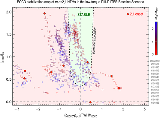
Figure 5. All stable and unstable points in a scan of  and
and  with 20 ms time resolution. The
  tearing onset is marked with large red circles. Time points are colored by the value of
  .
.
Download figure:
Standard image High-resolution imageIn figure 5 the third dimension,  , is represented by the color of the points. As mentioned in section 3,
  is calculated from ZipFits using carbon impurity CER data. Open circles represent time-slices prior to the onset of the 2,1 tearing mode with 20 ms time resolution (stable points), while filled circles represent the time-slice of the 2,1 island onset (unstable points).
The stability map in figure 5 shows that the central region bounded by the dashed boundary is populated mostly with stable points which suggests that stabilization might be occurring in that region. One instability landed within the expected stabilized region near the boundary. This could be caused either by effects not captured by the model, or it could be explained by the noise or a systematic uncertainty of the q = 2 surface location by ρ ≈ 0.02 in the equilibrium reconstruction. We label this region as stable region, whose boundary is estimated by modeling in section 5 and is shown by a thick dashed line. However, outside of the stable region the stable points do not isolate from the unstable points. As such, the data points in the  and
and  plane (without accounting for
  ) do not show an obvious correlation of the stability with the driven EC current.
The  data provides additional insights. On one hand, unstable points occur in the vicinity of low
  points (i.e. instabilities only occur when the rotation profile is flat). On the other hand, stable, low
  points occur (i) either near the unstable points or (ii) they lie in the stable region where the ECCD is well aligned and unstable points are absent (i.e. plasmas with flat rotation profiles cannot survive w/o ECCD). (i) Implies that the stable low
  points in the vicinity of unstable points belong to the same discharges as they approach the instability onset and therefore these points are transients, not operationally stable equilibria. This can be elucidated by excluding all points with
  from the stability map, as these points are stabilized by the rotation, i.e. they are stable with or without ECCD and therefore they do not carry information about the efficacy of ECCD stabilization.
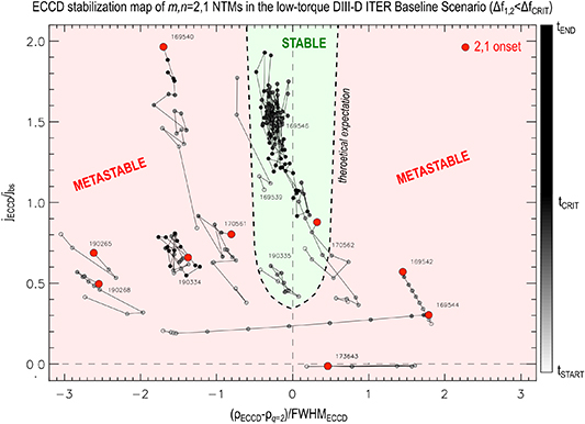
Figure 6 shows the stability map retaining only those points below the critical differential rotation (for clarity, these points correspond to the ones in the unstable shaded region in figure 3). In addition, points that belong to the same discharge are connected with straight lines in figure 6. Note that the unstable discharges spend an average of  ms at
ms at  before the 2,1 onset. The color of the stable points reflects their time relative to
  . The time-slices after
  are shown with solid black.
Figure 6. All stable and unstable points with  in a scan of
  and
and  . The
. The  tearing onset is marked with large red circles. The small circles represent 20 ms time windows w/o a 2,1 island. In the unstable shots, the colors reflect the points' proximity to the onset time. In the stable shots, the colors reflect the time in the flattop.
Download figure:
Standard image High-resolution image
Figure 6 shows that without well aligned ECCD every stable point is connected to the onset of a 2,1 tearing instability; hence they are not operationally stable, as mentioned earlier. In other words, despite being labeled as 'stable', one cannot operate the plasma in those points, as the plasma quickly evolves into a state where the 2,1 island is destabilized. Hence, the region outside of the stable region is labeled as metastable. In contrast, it is also clear that the plasmas can survive  without the onset of a 2,1 tearing mode when the ECCD is well aligned with the q = 2 rational surface in the stable region.
For clarity, we note that one discharge (190 335) with well aligned ECCD was terminated by an  island. Here all 4 available gyrotrons were focused at q = 2 (i.e. no
  at
at  ). The plasma differential rotation approached zero while multiple sawtooth crashes occurred but 2,1 islands did not grow, provided that the ECCD was well aligned with q = 2. This suggests that stabilization is possible even at
  . However the plasma is prone to tearing modes at low differential rotation: at
  , the
, the  NTM is the most unstable tearing mode when ECCD is not used but when the ECCD is focused at q = 2, the second most unstable mode grows and causes disruption (the
  tearing mode in this case). When
  is driven both at q = 2 and
  (169 546 and 169 539), the plasma survives the pre-programmed flattop.
5. Modeling the transition between stable and metastable states
In this section we use the modified Rutherford-equation (MRE) to estimate the boundary of the stable domain in the parameter space of  and
and  as in a former study [37], but now in the low-torque IBS, at low differential rotation. The MRE reads:
Here  is the resistive time-scale,
  is the minor radius coordinate of the q = 2 rational surface,
  is the full island width, t is the time,
  is the equilibrium classical stability index (here
  ),
),  is the perturbation of the classical tearing stability index caused by
  [13, 17],
  is the bootstrap current density relative to the total current density,
  cm is the equilibrium magnetic field shear length-scale at q = 2,
  cm is the transport threshold island width [2, 6, 21, 66–68],
  cm is the marginal island width at which the neoclassical growth becomes dominant (this equals a few times the ion banana orbit width) and K1 is the effectiveness parameter [14, 23]. These parameters are determined in a previous work [62]. Setting
  at
at  , equation (1) gives the boundary for just removing the metastable parameter space,
  . The effectiveness of replacing the missing bootstrap current depends on both the relative size of the island (
 ) and the alignment between the electron cyclotron beam and the q = 2 surface,
  (at
(at  ). The effectiveness of changing
  also depends on the alignment,
  . Both factors can be negative, i.e. destabilizing, if the misalignment is large. The resulting curve y(x) is shown in figures 5 and 6 with a thick dashed line. This boundary gives a fairly good, although not perfect, isolation between most stable and unstable points.
6. Summary, implications and open questions
This paper reports the first preemptive stabilization of rotating  NTMs in the low-torque ITER baseline scenario in DIII-D. Scans of ECCD amplitude and location were conducted and the onset condition of the 2,1 tearing modes was investigated both in shots with and without ECCD.
It was shown that in all unstable discharges of our database the onset of the 2,1 island occurs at low differential rotation, regardless of the use of ECCD. Explanation of the unfavorable property of low differential rotation in 2,1 tearing stability is offered as follows. The 2,1 seed islands are triggered by the sawtooth and hence they rotate at the 1,1 frequency. When  , the seed island drifts with respect to the ions at q = 2 giving rise to stabilizing ion polarization currents, but this stabilization is weak when
  . As high differential rotation naturally stabilizes the plasmas, the effect of ECCD can only be tested when
  .
.
Next, the ECCD stabilization map was constructed in terms of the  ,
,  and
and  variables, which shows that (i) there are no 2,1 onsets with well aligned ECCD and (ii) there are no stable equilibria at low differential rotation without well aligned ECCD. The boundary between the stable and metastable parameter space is estimated by the MRE, which reasonably, although not perfectly, agrees with the data.
We conclude that the 2,1 island avoidance at low differential rotation was achieved by the use of electron cyclotron waves in these experiments. The presented data are highly supportive that the observed stabilization is achieved by the electron cyclotron current replacing the missing bootstrap current in the island. However, given the limited size of our database, the use of additional ECCD at  in some discharges and the limited power in the ECH only shot, more data are needed to improve the confidence of the latter.
Further, we have reported signatures of stabilization at  , although the amount of time this shot spent at low differential rotation is less than the average time the unstable shots spent. This is a potentially important observation, as it suggests that narrow islands can be suppress by lower electron cyclotron current density as long as the pressure profile has not yet completely flattened at the O-point. This would be favorable, as the impact of continuous steady ECCD operation on the fusion energy gain factor (Q) would be less than previously thought [44]. However, further experiments will be needed to determine the minimum
  required to maintain stability and thus to precisely address its effect on Q in this scenario. In the discharge that achieved stability with 3.5 MW EC power at
  , the H-mode confinement enhancement factor (H98) drops by 14% (from 1.05 to 0.9). Stabilization at
  could occur due to the facts that (i) the ECCD modifies
  and/or (ii) that narrow islands are not entirely flat due to the finite cross-field transport in the O-point region. At finite cross-field transport the fast parallel transport along the field lines of internal nested flux surfaces of the island do not completely remove the bootstrap current in the O-point region, as opposed to islands much larger than the transport boundary layer within the island separatrices [2, 6, 20]. On the other hand, operating the ECCD only when
  (still preemptively) would further improve the time average of Q.
These results are consistent with and support the recently developed understanding of the 2,1 tearing stability in the DIII-D ITER baseline scenario [59, 69], that the 2,1 onset occurs at the time and frequency of a sawtooth precursor when the rotation profile flattens at various times in the discharge regardless of the current profile relaxation phase. This study also suggests that preserving the plasma differential rotation is key to maintaining passive stability in the ITER baseline scenario in DIII-D. Experiments testing the actuators to prevent the differential rotation collapse will be discussed in a future publication.
Finally, how much  is required for passive stability and if ITER will be able to maintain it remains an open question. This calls for simultaneous modeling of the sawtooth instability growth, the rotation profile evolution and seed-island stabilizing mechanisms arising from the differential rotation in ITER.
Acknowledgments
This material is based upon work supported by the U.S. Department of Energy, Office of Science, Office of Fusion Energy Sciences, using the DIII-D National Fusion Facility, a DOE Office of Science user facility, under Awards DE-FC02-04ER54698, DE-AC52-07NA27344 and DE-FG02-86ER53218. The data that support the findings of this study are available from the corresponding author upon reasonable request.
Disclaimer
This report was prepared as an account of work sponsored by an agency of the United States Government. Neither the United States Government nor any agency thereof, nor any of their employees, makes any warranty, express or implied, or assumes any legal liability or responsibility for the accuracy, completeness, or usefulness of any information, apparatus, product, or process disclosed, or represents that its use would not infringe privately owned rights. Reference herein to any specific commercial product, process, or service by trade name, trademark, manufacturer, or otherwise does not necessarily constitute or imply its endorsement, recommendation, or favoring by the United States Government or any agency thereof. The views and opinions of authors expressed herein do not necessarily state or reflect those of the United States Government or any agency thereof.