


Abstract
The International Fusion Materials Irradiation Facility (IFMIF) is a project aiming to investigate candidate materials to be used in the most exposed zones of future fusion reactors. The linear IFMIF prototype accelerator (LIPAc), presently under commissioning in Rokkasho, Japan, is a prototype of the frontend section of one of the IFMIF accelerators. Eight quadrupole magnets, six pairs of corrector magnets and one dipole are responsible for generating the magnetic fields needed for a proper beam handling along the 10 m long LIPAc high energy beam transport line, which connects the end of the superconducting radio frequency Linac with the beam dump. A novel design of combined magnets with the correctors integrated in the quadrupole poles is chosen for compactness reasons. The different stages of the production of the combined magnets, from the magnetic and mechanical design to their manufacturing and testing, including exhaustive characterization of the magnetic performance are described in this work. The results from the tests revealed the quality of the magnetic field produced. The materials selection was done carefully, to withstand the high levels of ionizing radiation expected at the magnet locations. This paper focuses on the activities performed in Europe, before sending the magnets to Japan for their installation and commissioning at the Rokkasho site.
Export citation and abstract BibTeX RIS

Original content from this work may be used under the terms of the Creative Commons Attribution 4.0 licence. Any further distribution of this work must maintain attribution to the author(s) and the title of the work, journal citation and DOI.
1. Introduction
The linear IFMIF prototype accelerator (LIPAc) is a deuteron accelerator aiming to reach 9 MeV of beam energy with a current of 125 mA in continuous wave [1–3], currently under commissioning in Rokkasho, Japan. It is a 1:1 scale prototype of the low energy part of the accelerators foreseen as drivers of the neutron source for fusion reactor materials testing IFMIF [4, 5]. The challenging beam properties (high power and space charge) of the IFMIF accelerator, together with its RAMI requirements, demand the development and tests of this prototype for validating the accelerator design.
The LIPAc accelerator (see figure 1) is composed of an ion source, a low energy beam transport line (LEBT), a radiofrequency quadrupole (RFQ) accelerating deuterons up to 5 MeV, and a superconducting RF (SRF) Linac based on half-wave resonators, to accelerate the beam up to 9 MeV. The different accelerator components have been supplied by European countries as part of the Broader Approach Agreement between Europe and Japan [5].
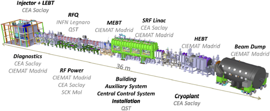
Figure 1. LIPAc (linear IFMIF prototype accelerator).
Download figure:
Standard image High-resolution imageThe high energy beam transport (HEBT) line [6] connects the exit of the SRF Linac down to the entrance of the beam dump [7] where the beam is stopped. The HEBT line has been designed to transport correctly the high power beam, minimizing the beam losses and adapting the beam parameters at the beam dump entrance to those required for a correct stopping. Given the LIPAc mission as validation prototype, a full set of beam instrumentation has been included to characterize exhaustively the beam.
Figure 2 represents an isometric view of the LIPAc HEBT line, which includes several room temperature electromagnets to drive the beam: a dipole and eight quadrupoles. The dipole bends the beam 20° horizontally, with the objective of reducing the radiation—generated from the beam interaction with the beam dump material—impinging on different HEBT components and especially on the SRF Linac. The LIPAc HEBT quadrupoles, which are the object of this article, are grouped into three groups:
- The first group, called 'first triplet', includes the magnets HMA01, HMA02 and HMA03 and it is located at the beginning of the HEBT line. It adapts the beam coming from the SRF Linac in order to have optimum conditions along the diagnostic plate, which is a set of beam diagnostics located right after the triplet.
- The second group, called 'doublet', includes two magnets: HMA04 and HMA05. These quadrupoles are needed to limit the beam size at the dipole entrance, allowing to reduce the tube aperture and avoiding particle losses. Additionally, during the commissioning phase, they will allow the correct focusing of the beam during the emittance measurements based on the quadrupole scan technique using the first triplet magnets.
- The third group, called 'second triplet', which is composed of the magnets HMA06, HMA07 and HMA08, will increase the beam size so that its power density at the beam dump is sufficiently low to be safely stopped.

Figure 2. Model of the LIPAc HEBT line, where the eight magnets presented in this paper are tagged from HMA01 to HMA08.
Download figure:
Standard image High-resolution imageAdditionally, two pairs of horizontal–vertical corrector coils are included at each group of quadrupoles. They are used, in combination with beam position monitors, for a proper beam trajectory correction.
The use of resistive magnets is well established in particle accelerators, being their specifications in the case of linear accelerators less demanding than in circular machines. However, the LIPAC special features impose strong requirements on these magnets, and call for special solutions in their design and manufacturing:
- The necessity of strongly focalizing the beam to compensate the effect of the high space charge, together with the building constraints, led to a configuration with groups of short magnets (in beam direction), with small distance between them. As it will be explained in section 3, this space limitation determines the quadrupole magnet design, forces to include correctors and quadrupole coils in the same yoke and implies also a specific design of the magnet connections.
- The high power of the beam leads to a big diameter of the beam tube, to avoid its heating and its activation by the beam particles. Consequently, the magnets have large apertures and operate in conditions close to saturation.
- In the case of the second triplet, the large gradients needed to defocus the beam resulted in a large magnet size, complicating their manufacturing and the tolerances accomplishment.
The interaction of the high current continuous beam with the beam dump (which is located at only 2.5 m distance of the last magnet) gives rise to neutron and gamma radiation. Part of this radiation reaches the magnets through the aperture in the beam dump shielding needed for the beam tube. Therefore, requirements of radiation resistance must be imposed in all insulators, polymers and sensors of the magnets, and the iron impurity content must be limited to minimize activation assuring that manual maintenance is allowed. To simplify the design, manufacturing and tests, reducing costs and easing the procurement of components and spares for maintenance, the magnets of each group are identical (except for the corrector coils, which are included only in two magnets of each group, being absent in the central triplet magnets HMA02 and HMA07). The power supplies for the magnets of the same group are also identical.
This paper summarizes the different stages of production of the combined quadrupole and corrector magnets, from their design to their manufacturing and testing. It is organized as follows: section 2 presents a description of the magnets and their main requirements. Section 3 discusses and justifies the design choices, and summarizes the calculations performed and the resulting design. In section 4, the principal features of the selection of materials and manufacturing are given. In section 5, the experimental results provided by the magnetic testing of each magnet on a rotating coil bench are analyzed. Section 6 presents a brief description of the cooling system and of the power supplies. Finally, section 7 summarizes the conclusions and the main lessons learned along the whole process, which could be of interest for similar projects.
2. Main parameters and requirements
Beam dynamics simulations of the HEBT line determined the main specifications of the different magnets. Other requirements as the available space, ionizing radiation environment and installation considerations were also taken into account in the design.
2.1. Main parameters
The main performance requirements for the magnets, obtained from the beam dynamics analysis [8] performed with Tracewin code, are given in table 1. TraceWin code [9] has been considered as the reference code in the LIPAc project, as it includes 2D and 3D space charge models, the capability of modeling the different accelerator elements either using analytical expressions or field maps, a correction procedure based on diagnostics as well as an automatic procedure to analyze static and dynamic errors for all the Linac elements using several computers based on a client/server architecture. The nominal quadrupole gradients were obtained after performing extensive beam dynamics calculations to optimize the beam transport along the HEBT line fulfilling the line requirements [6]. Positive values mean that the magnet focuses the beam in the horizontal plane and defocuses the beam in the vertical plane. The design (maximum) gradients were obtained from these values, adding some margin to allow tuning during commissioning and operation. In the case of the first triplet and doublet, this margin also considers the performance of emittance measurements based on the quad scan technique [10, 11].
Table 1. Main performance requirements for the magnets in the HEBT line.
| First triplet | Doublet | Second triplet | |||||||
|---|---|---|---|---|---|---|---|---|---|
| Designation | HMA01 | HMA02 | HMA03 | HMA04 | HMA05 | HMA06 | HMA07 | HMA08 | |
| Quadrupoles | |||||||||
| Maximum gradient, T m−1 | 14.5 | 8 | 12.75 | ||||||
| Aperture radius rA, mm | 45 | 68 | 68 | ||||||
| Maximum integrated field, | 0.0813 | 0.0612 | 0.163 | ||||||
| T m (r = 75% rA) | |||||||||
| Magnetic length, mm | 166.1 | 150.0 | 250.7 | ||||||
| Nominal gradient, T m−1 | 6.5 | −10.6 | 5.9 | −4.4 | 4.4 | −3.2 | 6.7 | −9.0 | |
| Corrector field | <30 G m | <30 G m | <30 G m | ||||||
With the aim of minimizing magnet size and cost, aperture diameters were defined as small as possible. The beam pipe internal radii were chosen after a large number of simulations considering possible errors, and giving large margins, to assure that the number of beam particles hitting the beam pipe is kept under the established limits for the HEBT design [6]. The magnet aperture radii (rA) were defined by adding 1.5 mm to the pipe internal radius to account for the pipe thickness, and an additional margin of 1.5 mm to allow for manufacturing and assembly tolerances of the components.
The required maximum dipole field needed for the orbit correction was obtained from the simulations of non-nominal conditions, assuming different errors in the quadrupoles and dipole which are briefly described in the following paragraph.
2.2. Quadrupole field requirements
Allowable tolerances in the quadrupole fields and in the magnets positioning were obtained from statistical beam dynamics simulations [6, 8]. The analysis was done using several hundreds of combinations of errors in the magnets with random amplitudes. The errors included displacement and rotation of the magnetic configuration, due to manufacturing or alignment errors, as well as deviations of the field values due to power supply errors. Both time independent/slow varying errors (called static errors), which can be corrected with steerers, and fast varying (dynamic) errors, that cannot be corrected, were considered. The magnet tolerances were chosen to obtain a correct beam centering along the line, a minimum distortion of beam size evolution, especially critical at the beam dump entrance, and a minimization of particle losses along the HEBT line. Details about these analyses can be found in references [6, 8].
Table 2 summarizes the maximum allowable errors obtained from the simulations: magnet displacements of ±0.2 mm and rotations of ±0.9° in x, y axes (centered in the magnet and transverse to the beam direction) and ±0.3° in z axis (magnet axis parallel to the beam direction). Tolerances in the quadrupole fields of half these values were defined, leaving margins of the same values for the magnet positioning at the accelerator. Therefore, magnetic center deviation was specified to be less than 0.1 mm and maximum angular deviations of 0.45° in x, y axes and 0.15° in z axis were established. On the other hand, the maximum static error in the quadrupole gradient of ±2%, with maximum temporal variations of ±0.1%, is widely covered by the requirements imposed on the quadrupole power supplies: 0.1% accuracy and ±0.03% precision, including all possible sources of current variation (table 10).
Table 2. Maximum allowed errors in the LIPAc HEBT line. Quadrupole fields defined by beam dynamic studies and quadrupole magnet tolerances.
| Allowable error | Magnet tolerance | ||
|---|---|---|---|
| Static | Dynamic | ||
| Quadrupole gradient (%) | ±2 | ±0.1 | |
| Quadrupole displacement (mm) | ±0.2 | ±0.01 | ±0.1 |
| Quadrupole rotation (X, Y) (°) | ±0.9 | ±0.06 | ±0.45 |
| Quadrupole rotation (Z) (°) | ±0.3 | ±0.06 | ±0.15 |
Concerning field quality, typical specifications for the harmonic amplitudes normalized to the principal mode of 0.1% (10 units over 10.000) were considered in the region inside 75% of the magnet mechanical aperture (containing 99.9% of the beam), which is called the good field region (GFR). This value was specified despite LIPAc being a linear accelerator, with the aim of obtaining a high quality product. According to magnetic simulations, these field quality requirements, together with those related to the alignment of the magnetic field, impose a global shape tolerance in the obtained iron pole profile of ±20 microns.
2.3. Space requirements
The challenging combination of strong space charge forces and high continuous beam power demands a compact HEBT design with strong focusing in specific regions, being the spaces without focusing as short as possible. This fact, together with the available length in the building and the space requirements for other equipment (diagnostics, vacuum, shield, etc) limits the available space for the magnets in the beam direction and, as it will be seen in section 3, resulted in important implications in the electromagnetic and detailed design.
2.4. Radiation requirements
As mentioned before, the magnets will work under the presence of ionizing radiation. This radiation (neutron and gamma) comes from the interaction of the deuteron beam with a copper cone [7], which is the stopping element inside the beam dump. Dose rates of up to 29 Gy/h, and total absorbed doses at the end of the accelerator lifetime of 1.25 × 10⁵ Gy, have been estimated at the magnet locations [6]. This has several implications:
- The materials must withstand the radiation that exists during accelerator operation. This determines the materials selection and also the general layout of the magnet: electrical and hydraulic connections of the quadrupole coils with their corresponding joints (brazing, soldering) were located at a dedicated region with lowest radiation, farthest from the accelerator axis.
- Magnets activation must be minimized by a proper choice of materials considering their impurity content. In particular, a Co content of the iron of less than 50 ppm was required.
2.5. Cooling requirements
For the quadrupole water cooling, typical assumptions for room temperature magnets [12] were considered. A pressure loss of 5 bar, maximum water velocity of 3 m s−1—to avoid flow induced vibration and erosion of the coolant passage—, and a maximum water temperature increment of 25 °C, were defined.
2.6. Other requirements
The iron saturation should be minimized. The power consumption and the iron weight must be also reduced as much as possible.
To allow the assembly of the beam tube, the magnets must be designed and constructed in such a way that they can be split into upper and lower parts. Their design must assure the precise and reproducible positioning of the two halves.
Finally, regarding to the joints of the different pieces forming the magnets, and in particular the joint between the magnet and the base plates, they must bear the seismic loads required by the LIPAc project (horizontal acceleration of 0.4 g, vertical acceleration of 0.2 g).
3. Magnets design
The design of the magnets was carried out considering all the requirements explained in the previous section. The integrated design process considered different parameters coming from beam dynamics, cooling system, power supplies, fabrication and integration, as well as the cost implications of the different options in an iterative process. Section 3.1 explains the design choices made regarding configuration, coil conductors and geometry and yoke material and profile. Section 3.2 summarizes the magnetic simulations performed in support of the design, including the quality of the resulting fields and the field coupling between the different magnets. A short description of the cooling and general layout is given in section 3.3. Finally, the design parameters and the magnetic acceptance criteria are summarized in section 3.4.
3.1. Configuration and main design choices
The space limitations mentioned in the previous section preclude the use of individual corrector magnets based on the typical window frame configuration, despite its very good dipole field quality. A non-standard configuration, where correctors and quadrupole coils share a common yoke (see figure 3), was proposed to meet the accelerator needs. In contrast to other alternatives [13], where steerer coils are placed around the return yoke, the challenging combination of large magnet aperture and short length makes the location of the corrector coils around the pole tips more beneficial, as it improves its efficiency (smaller steerer current required for a given dipole field) and reduces the fringe fields. Four quadrupole coils, four vertical steering coils and four horizontal steering coils are integrated in each combined magnet. By choosing the right polarity of the four coils, instead of a quadrupole field, an almost dipolar vertical or horizontal field can be created at the GFR.
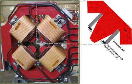
Figure 3. Picture of one of the quadrupoles (HMA01) and schematic representation of the quadrupole and corrector coils around the iron pole.
Download figure:
Standard image High-resolution imageIn this paper vertical/horizontal corrector denotes a steerer which generates vertical/horizontal magnetic field (which therefore tilts the beam in horizontal/vertical direction). Corrector coils are located below the quadrupole coils, to occupy the space available close to the pole tips. Other alternatives for embedded correctors, such as cos θ or window frame coils, were discarded as they would lead to an increase of the quadrupole apertures and consequently to an increase of the magnetic field at the pole tips, the cost and the magnet complexity.
Although the chosen common yoke coils configuration produces a field with a significant sextupolar component, being LIPAc a linear accelerator, its effect on the beam transport is negligible. This was confirmed by beam dynamics simulations, as explained in the next section 3.2.
3.1.1. Quadrupole and corrector coils
The conductor choice was made as a trade-off between the impact on the overall dimensions and the cooling and power requirements. The main parameters of the different conductors are included in table 3. For the quadrupoles, water cooled coils, with current densities between 5 A mm−2 and 6 A mm−2, were chosen. High conductivity oxygen-free copper OF-OKTM hollow conductors, insulated with a layer of 0.25 mm epoxy impregnated fiberglass tape, were considered, with 1.5 mm insulation around the coil. Thecorrector coils were chosen to be made with air cooled electrolytic tough pitch (ETP) conductors, with current densities limited to 2 A mm−2.
Table 3. Conductor dimensions for quadrupole and corrector coils.
| First triplet | Doublet | Second triplet | |||
|---|---|---|---|---|---|
| a (mm) | 7.0 | 7.0 | 8.0 | Quadrupole coil R = 1 mm |
|
| b (mm) | 8.0 | 8.0 | 10.7 | ||
| d (mm) | 3.5 | 3.5 | 5.8 | ||
| a (mm) | 2.0 | 2.0 | 2.0 | Corrector coil R = 0.5 mm |

|
| b (mm) | 5.0 | 7.0 | 5.0 |
The quadrupole coil geometry was chosen to reduce the length of the magnet. Consequently, quadrupole coils with a small number of turns per layer (meaning indicated in figure 4), using the rectangular conductors of table 3, with the short side in the bending direction, were chosen. The quadrupole coil cross sections and geometries resulting from the design are shown in figure 4.
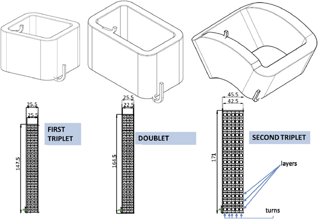
Figure 4. Quadrupole coils geometry and cross section for the three different magnet types. Units in mm.
Download figure:
Standard image High-resolution imagePlanar coils are used for the first triplet and doublet. For the second triplet, 30° truncated cone shape coils, which fit better the pole profile, were chosen for both quadrupole and correctors, with the objective of reducing the iron saturation. The required value of ampere·turns to obtain the design integrated field, was determined for each quadrupole type by magnetic simulations, and it is indicated in table 4, together with the number of layers and turns of each quadrupole coil.
Table 4. Ampere·turns, number of layers and turns per layer in each coil, integrated field and integrated field quality at 0.75rA for the different HEBT quadrupoles.
| First triplet | Doublet | Last triplet | Units | |
|---|---|---|---|---|
| Ampere·turns | 11690 | 14700 | 23475 | A turns |
| Number of layers | 17 | 19 | 15 | |
| Turns per layer | 3 | 3 | 5 | |
| Integrated field (r = 0.75rA) | 0.085 | 0.066 | 0.169 | T m |
| b6 | 0.06 | 0.03 | 0.14 | 10–4 |
| b10 | 1.14 | 0.02 | 0.28 | 10–4 |
| b14 | 3.09 | 4.46 | 3.13 | 10–4 |
Concerning the correctors, double pancake coils with a geometry adequate to the chosen configuration in the quadrupole yokes were designed. Figure 5 shows a 3D model of the corrector coils for the first and second triplet of magnets.
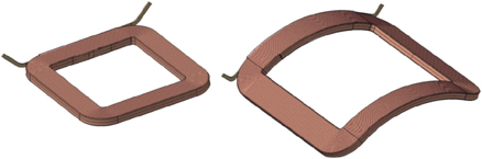
Figure 5. 3D model of corrector coils corresponding to a first triplet magnet (left) and to a second triplet magnet (right).
Download figure:
Standard image High-resolution image3.1.2. Iron profile
The material selected for the yoke is ARMCO® steel, due to its high saturation field (see figure 6) and purity [14].
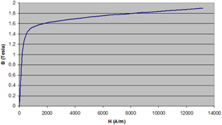
Figure 6. B/H curve of ARMCO iron [14].
Download figure:
Standard image High-resolution imageThe truncated hyperbolic pole profile was designed taking into account the specified magnet apertures, the quadrupole and correctors coil dimensions and allowing for a margin of 2 mm between coils and iron. The geometry was optimized by an iterative process in order to obtain the required gradients with minimum saturation, minimum harmonic content in the GFR as well as minimum iron length and weight. As the short magnet length affects the magnetic field distribution, 3D magnetic calculations were needed for this optimization. A parametric model with a few parameters determining the geometry of the pole and of the yoke was used in the optimization algorithm of the CERN field computation code ROXIE [15].
The parameters describing the iron geometry are shown in figure 7. The hyperbolic central part goes until point A, where a tangentially rectilinear part follows to point B. The harmonic content is basically determined by these two points. Point C defines a slopped line from the end of the tangent line in order to broaden the pole and prevent saturation in the pole tip. The remaining points around the coil are obtained taking into account the 2 mm space between coils and iron. Finally, the external yoke radius Rext must be large enough to avoid saturation in the return yoke, but not too large, to reduce the total iron weight and therefore the cost. Small plane regions (not shown in figure 7) were added at the pole corners (point B), with the objective of allowing precise measurements of the distance between adjacent poles. Due to the short length of the iron yoke no chamfers were included to avoid a strong decrease of the magnetic field.

Figure 7. Parametric model of the iron geometry (the plot shows a quarter of the yoke, rotated 45° from the beam reference frame).
Download figure:
Standard image High-resolution image3.2. Simulations
Given the reduced magnet length and the big aperture, 3D calculations were performed to obtain a precise estimation of the field quality and the fringe field effects. The simulations were done with the CERN field computation code ROXIE [15].
3.2.1. Quadrupole field
The results of the magnetic simulations for the quadrupole field, including the number of ampere-turns NI as well the harmonic content at the GFR radius, are shown in table 4. All quadrupoles show a low amplitude of integrated harmonics, normalized to the fundamental component B2, being the largest contribution (b14 harmonic) lower than 5 units 6 . The good field quality can be seen as well in figure 8 (left), which shows the integrated gradient uniformity at each point of the magnet aperture, defined as the difference in the integrated field from the value at the magnet center, expressed in %. At the GFR (marked with a black circumference in the figure), gradient uniformity is below 0.05% for all quadrupoles.
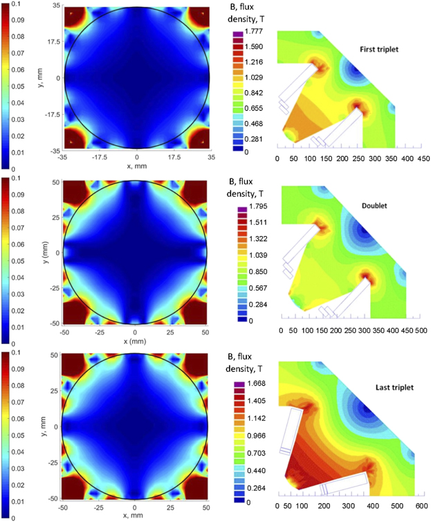
Figure 8. Left: gradient uniformity (difference between integrated gradient at (x, y) and at the magnet center expressed in %) for the different HEBT quadrupoles. GFR is marked with a black circumference. Right: magnetic induction (T) for quadrupole coils powered at the design (maximum) current. Coordinates are in mm.
Download figure:
Standard image High-resolution imageFigure 8 right shows the iron saturation when the quadrupole coils are powered at the design (maximum) current. The 2nd triplet quadrupoles show the highest saturation at the poles, in spite of the use of cone-shaped coils. The quadrupole saturation dependence on the excitation current was studied for the different magnet types. As observed in figure 9, the magnet behavior is linear up to 70%–80% of the maximum current, showing non-linearity for higher currents. During normal operation, the quadrupoles are expected to be powered at currents where linear behavior remains (the ratio between nominal and maximum current I/Idesign vary between 25% and 73%, depending on the specific quadrupole—see nominal and maximum gradients in table 1). According to the simulations, the saturation under normal conditions will be very small leading to a reduction of magnetic field less than 0.5% with respect to exact linear behavior.

Figure 9. Current transfer function (ratio between integrated magnetic field and current) for the different HEBT quadrupoles. The ordinates have been normalized to the value without saturation.
Download figure:
Standard image High-resolution image3.2.2. Corrector field
The required number of ampere·turns for the correctors and the characteristics of the field obtained from the magnetic calculations at the design (maximum) current are summarized in table 5.
Table 5. Corrector NI and integrated field quality at the GFR radius obtained from simulations in which correctors are energized at the design (maximum) current and quadrupole current is zero, for the different HEBT magnets. Multipole amplitudes are normalized to those of the main corrector harmonic.
| Magnet type | First triplet | Doublet | Last triplet | Units |
|---|---|---|---|---|
| Ampere·turns | 570 | 950 | 630 | A Turns |
| Number of layers per coil | 2 | 2 | 2 | |
| Turns per layer | 14 | 16 | 19 | |
| Horizontal corrector | ||||
| Integrated dipole field (A1) | 36.2 | 38.4 | 41.5 | G m |
| a3 | 3674 | 3437 | 3614 | 10–4 |
| a5 | 166 | 104.2 | 96.4 | 10–4 |
| Vertical corrector | ||||
| Integrated dipole field (B1) | 35.4 | 36.8 | 41.0 | G m |
| b3 | 3760 | 3590 | 3660 | 10–4 |
| b5 | 170 | 81 | 171 | 10–4 |
A significant sextupole component (about 35% of the dipole field) can be observed, while the rest of harmonic amplitudes are lower than 2% of the dipolar one. The sextupole field is due to the distribution of the corrector in four coils and to the surrounding quadrupole yoke. This field quality is acceptable, being LIPAc a linear accelerator, as it was checked by beam dynamics simulations which did not show any appreciable deterioration of the beam transport.
Figure 10 shows the field created by the first triplet horizontal corrector coils, together with that generated by the quadrupole coils for comparison. It can be observed that the field created by the corrector coils deviates with respect to a pure dipole field and that this deviation increases with the distance from the magnet center.

Figure 10. (a) Magnetic field lines for the first triplet with energized horizontal corrector coils (zero quadrupole coils current). The whole quadrupole and the detail of the aperture are shown. (b) Magnetic field lines for energized quadrupole coils (without corrector current) at the aperture in the same magnet.
Download figure:
Standard image High-resolution image3.2.3. Quadrupole–corrector field coupling
At high quadrupole currents, the iron saturation reduces the effect of the steering coils. Therefore, the corrector current needed to obtain a given trajectory correction will be larger. Figure 11 shows the corrector field at maximum current when the quadrupole is powered at different currents. Although this quadrupole–corrector coupling is high at the quadrupole maximum current—a maximum decrease of the steerer field of 35% with respect to the case without quadrupole field is observed for the second triplet magnets—, it will be lower than 2% during normal operation. The maximum current of the correctors (table 5) has been defined taking into account this effect, to guarantee that even in the case of maximum quadrupole current, the correctors are able to give the required integrated field of 30 G m. As observed in figure 11, at lower quadrupole currents there is larger margin in the maximum corrector integrated field that can be achieved with respect to the required value.

Figure 11. Corrector integrated field at maximum corrector current, for different quadrupole currents.
Download figure:
Standard image High-resolution imageThe corrector harmonic content is not affected by the quadrupole current. Also, given the low corrector currents, they do not affect the field produced by the quadrupole coils nor that created by the second corrector coils located in the same yoke.
3.2.4. Quadrupole–quadrupole coupling
Given the proximity between adjacent quadrupoles, the field coupling among them was studied using Roxie models that combine the quadrupoles of each group (see figure 12). It was concluded that the coupling is negligible, being its effect in the field at the magnet center lower than 0.3%, for the three quadrupole groups. No coupling effect is observed either among correctors from different combined magnets. As an example, figure 13 shows the magnetic field at the GFR radius, generated by the individual quadrupoles of the first triplet, and that produced by the combined model of the three, for the nominal currents.
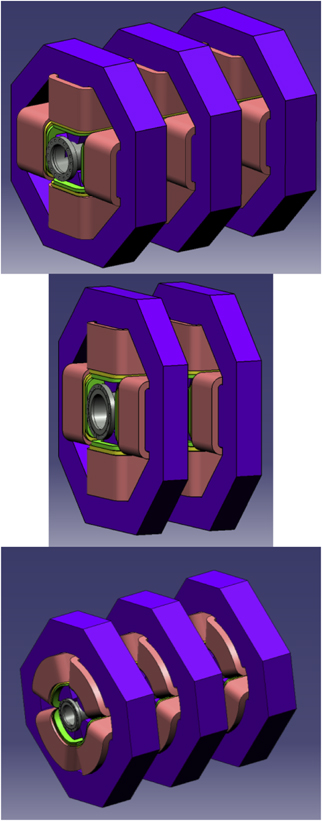
Figure 12. Combined model for the HEBT first triplet (up, left), doublet (up, right) and last triplet magnets (down).
Download figure:
Standard image High-resolution image
Figure 13. Magnetic field at the GFR radius produced by each of the three quadrupoles of the first triplet individually, and total magnetic field produced by the three magnets simultaneously powered at the nominal current.
Download figure:
Standard image High-resolution image3.2.5. Magnet design validation with beam dynamics simulations
Beam dynamics calculations were performed to analyze the effect of the quadrupole field non-uniformity and fringe fields on the beam transport. The field maps obtained from the electromagnetic simulations were included in the beam dynamics simulations. Negligible variations were observed in the beam size, position and characteristics with respect to the results obtained with equivalent hard-edge models of the magnets. Additionally, the corrector field maps were also included, thus validating their use in LIPAC accelerator despite their high sextupole component.
3.3. Cooling, general layout and maintenance considerations
In each magnet, the four quadrupole coils are electrically connected in series and so are the four coils of each corrector. Hydraulically, the four quadrupole coils are connected in parallel. Corrector coils, having sufficiently low current densities, are air cooled. The main cooling design parameters are shown in table 6.
Table 6. Cooling design parameters for the HEBT quadrupoles at the design (maximum) current.
| First triplet | Doublet | Last triplet | Units | |
|---|---|---|---|---|
| Pressure drop | 5 | 5 | 5 | bar |
| Water velocity | 1.55 | 1.39 | 1.34 | m s−1 |
| Friction factor | 0.0383 | 0.0395 | 0.0345 | — |
| Reynolds number | 4803.8 | 4297.7 | 6903.6 | — |
| Water flow rate/coil | 0.89 | 0.80 | 2.13 | l/min |
| Temperature increase | 13.05 | 22.36 | 19.53 | °C |
With respect to the magnet layout, as mentioned in section 1, taking into account the fact that neutron exposure decreases with the distance from the accelerator axis, it was decided to make all the quadrupole electrical and hydraulic connections far from the axis, at the lateral edge of the magnet. To allow accessibility to the beam tube and diagnostics in the space between magnets, it was established that the space occupied by the connections in the beam direction could not exceed the magnet length.
This configuration is also useful to ease maintenance activities, taking into account the residual radiation due to the activation of the magnet itself and of other accelerator elements [6]. The magnets will become activated due to the neutron radiation present during accelerator operation, which for the last quadrupole HMA08 is around 108 n/cm2/s on average [16]. Dose rates beyond the limit for hands-on maintenance will be achieved at the second quadrupole triplet, and specially in the vicinity of this last magnet, for short cooling times. After 6 months of full power operation and 1 day cooling, dose rates due to magnet activation will be around 40 μSv/h at 30 cm radially apart from the magnet external surface, decreasing up to 4 μSv/h after 1 week cooling. The main isotopes responsible for the residual doses are Fe59 and Mn54, generated from the iron of the yoke, whereas its cobalt content, limited to 50 ppm, does not contribute significantly.
3.4. Summary of design parameters and magnetic acceptance criteria
The main parameters of the magnets (maximum current Idesign, corresponding voltage drop between terminals V, quadrupole cooling water temperature increase ΔT, dimensions) resulting from the design presented in this section, are shown in table 7.
Table 7. Main electrical and physical parameters of the HEBT combined magnets.
| 1st triplet | Doublet | 2nd triplet | Units | ||
|---|---|---|---|---|---|
| Length | 213 | 181 | 332 | mm | |
| Height | 736 | 900 | 1119 | mm | |
| Iron length | 130 | 98 | 204 | mm | |
| Weight | 475 | 525 | 1600 | kg | |
| Quad | Idesign | 229.2 | 257.9 | 313.0 | A |
| V | 14.2 | 19.4 | 37.1 | V | |
| ΔT | 13.1 | 22.4 | 19.5 | °C | |
| Corrector | Idesign | ±20.4 | ±29.7 | ±16.6 | A |
| V | 2.7 | 3.5 | 4.5 | V | |
Table 8 summarizes the magnetic tests acceptance criteria which have been specified for these magnets. The maximum quadrupole harmonic content demanded (0.1% of the main harmonic) was explained in section 2 (quadrupole field requirements) and shown to be achievable with the magnetic simulations presented in section 3.2 (table 4). With regard to the correctors, the maximum harmonic amplitudes with respect to that of the dipolar component established are: 40% for the sextupolar component and 5% for the rest of harmonics. These values are based on the results of the magnetic simulations performed (table 5) which have been considered acceptable given that, as explained in section 3.2, the beam dynamics simulations using the modeled corrector field maps showed a correct beam transport. The acceptance criteria for the quadrupoles include also the maximum distance between the magnetic and mechanical centers and the maximum angular deviation of the field, which were obtained from the beam dynamics error simulations (see section 2).
Table 8. Magnetic acceptance criteria which must be fulfilled in the GFR (radius of 34 mm in the case of the first triplet magnets and 51 mm for doublet and second triplet magnets).
| Parameter | Acceptance value | |
|---|---|---|
| Quadrupoles | Integrated field (T m) at Idesign | >97% maximum value (table 1) |
| Harmonic content | Amplitudes of each harmonic | |
| from n = 1 to 14 < 0.1% main | ||
| harmonic (n = 2) | ||
| Distance between magnetic and | <0.1 mm | |
| mechanical center | ||
| Field angular deviation | <0.143° (2.5 mrad) | |
| Correctors | Integrated field (G m) at Idesign | >95% maximum value (table 1) |
| Harmonic content | Amplitude of each harmonic | |
| from n = 2 to 12, | ||
| except n = 3 < 5% main harmonic | ||
| (n = 1) b3, a3 < 40% a1, b1 |
Additionally to demonstrate the correct magnet performance it has been required that the integrated fields obtained at the maximum current be close to the theoretical ones within a small margin (3% in the case of quadrupoles and 5% in the case of correctors).
4. Manufacturing of the magnets
The eight magnets were manufactured by the Spanish company ELYTT Energy. The process of manufacturing and the main material selection decisions are described in this section. Special attention was devoted to the selection of the functional non-metallic materials (insulators, resins) which should bear the expected absorbed radiation doses and also to the composition of the iron for the yokes.
4.1. Manufacturing of the yokes
Given the short number of identical magnets to be manufactured, single iron pieces were used for the yoke quadrants. The material used is pure iron AME from AKSteel which is equivalent to ARMCO® Grade 4, being this designation used by the supplier for large non-standard blocks as those required for the LIPAc HEBT magnets. Particularly, the second triplet magnets, which are the largest, needed batches with transversal section of 590 mm × 590 mm for each quadrant. Coercivity is around 100 A m−1. With respect to the chemical composition, the yoke material is characterized by a low C and Mn content, a Co content of less than 50 ppm and a minimum Fe content of 99.75%. The iron of a given quadrupole was obtained from adjacent material of the same batch, to maximize the homogeneity among the different quadrants of each magnet.
The manufacturing of the yoke quadrants was done in two stages: first, a computer numerical control (CNC) machining of the quadrants, and second, a fine wire erosion electrodischarge machining (EDM) of the assembled yoke to achieve in the pole tip profiles the specified global mechanical tolerances mentioned in section 2. Figure 14(a) shows a picture of the EDM process of one of the yokes.
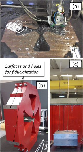
Figure 14. Pictures of the selected intermediate stages of the magnet manufacturing: (a) EDM machining of yoke poles and reference surfaces (b) iron yoke before placing the coils, the surfaces and holes observed from this view are marked and (c) coil inside the impregnation mold (long terminals can be seen outside the mold).
Download figure:
Standard image High-resolution imageRegarding the magnet fiducialization, six external reference surfaces with two perpendicular positioning holes each, were machined at the EDM stage. Some of these surfaces with the corresponding holes can be seen in the iron yoke picture in figure 14(b). The purpose of the positioning holes is to accommodate reflector holders with shank for the laser tracker alignment of the magnet at the magnetic test bench and after final assembly at the LIPAc accelerator premises.
The external reference surfaces and the positioning holes were characterized in a coordinate measuring machine, to provide mechanical alignment matrixes for the magnets. Also, the pole profile was measured at four different planes, to check the compliance with the specified tolerances. The measurements were repeated after dismounting the yoke into its four quadrants and assembling it again, showing good reproducibility. The results showed that tolerances were met in most of the pole surface for the first triplet and doublet yokes, which showed only some deviations (of less than 15 microns) in a few small regions. The second triplet yokes showed higher deviations, of up to 50 microns.
Figure 15 presents, as an example, the results obtained for magnet HMA07. These deviations, which varied with the z coordinate, being in most cases maximum at the central part of the yoke, were attributed to a slight bending of the wire when cutting the yokes (with a thickness up to 204 mm—see table 7). As it will be shown later, being this error symmetric, it does not affect significantly the quality of the resulting magnetic field, which even for the thicker magnets was shown to be inside the specifications.
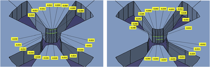
Figure 15. Results of 3D measurement of one of the poles of magnet HMA07 (deviations from nominal profile are shown in mm).
Download figure:
Standard image High-resolution image4.2. Manufacturing of the coils
Materials and processes involving the manufacturing of the coils were carefully selected in order to obtain coils with the correct dimensions, given the space constraints in the accelerator and in the magnet itself, and with enough radiation resistance.
4.2.1. Quadrupole coils manufacturing procedure
For the quadrupole coils, the conductors used are references 8279 and 8133 from Luvata (see table 3).
The conductor was wrapped with an E-type fiberglass tape (TISSTECH STB506TP) of 0.125 mm thickness applied with half overlapping, following norm EN-60317-0-4. For ground coil insulation, the same fiberglass tape was used with several half overlapping, until reaching a minimum insulation thickness of 1.5 mm all around the coil. Finally, a vacuum pressure impregnation process (VPI) was implemented to seal and rigidize each coil with a mixture of epoxy resins.
The impregnation of the individual coils was done in a specific mold for each type of magnet. As the coil terminals are very long (up to 2.2 m in the case of the second triplet magnets), to allow the connections being performed at the lateral side of the magnet, the molds include two chimneys made of silicon tubes, which hold these terminals.
4.2.2. Corrector coils manufacturing procedure
The double pancake coils were made with ETP copper CDA C11000 (minimum copper content 99.9%). The insulation of the conductor was made by polyesterimide varnish with an outer layer of polyamide-imide, which is designed to work up to 200 °C (Class H-200). The varnish was applied according to EN 60317-29, up to a thickness of 0.06 mm. The coils were wrapped with the same E-type fiberglass tape as that of the quadrupoles, with several half overlaps, until obtaining the final mass insulation thickness of 0.5 mm.
Since these coils are not water cooled, it was thought initially to use other techniques of ground insulation as wrapping with epoxy-fiberglass pre-preg, to avoid doing VPI, which is more expensive. However, the coils with pre-preg insulation failed the ground insulation test immersed in water. For this reason, a VPI process similar to that followed for the quadrupole coils was employed, impregnating several coils simultaneously in a mold.
4.2.3. Radiation resistance of coil materials
According to the CERN radiation damage databases the radiation resistance of all the materials employed for the coils manufacturing should be adequate for the LIPAc requirements (section 2). Radiation resistance suitability of polyesterimide varnish was checked in reference [17] while that of polyamide-imide varnish can be seen in reference [18]. Also according to this last reference and to [19], the epoxy resin does not present significant radiation effects until 5 × 10⁶ Gy.
4.2.4. Individual coils testing
All the coils were tested before and after the vacuum impregnation process through visual inspection, dimensional controls, and measuring their resistance, impedance and inter-turn insulation (capacitive discharge, 1 kV). Ground insulation was also checked after vacuum impregnation, applying 3 kV DC voltage with the coil immersed in water. A dielectric test (3.5 kV AC, 1 min) was also performed, re-checking after it the DC ground insulation.
Regarding quadrupole cooling, the cooling channel dimensions along all the conductor were checked along the different manufacturing phases, by passing through it balls with 2.5 mm (first triplet and doublet) and 4.5 mm (second triplet) diameter, driven by compressed air. Water tightness was also checked (50 bar, 5 min, pressure decrease at the end of the test lower than 2%).
A thermal cycling test (25 cycles) was performed in one coil per magnet. In this test, the coils were powered without cooling until the thermal switch (see section 4.3) opened, being then cooled with the nominal flow. Insulation tests were repeated afterward, to prove that no degradation of the resin had occurred. During this test the opening temperature of the thermal switches was also determined.
4.3. Assembly, connections and instrumentation
After factory testing, the coils were mounted on the quadrants, and joined by appropriate coil supports and retainers (see figure 16).
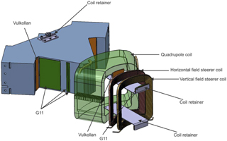
Figure 16. Complete quadrant model showing coils assembly.
Download figure:
Standard image High-resolution imageFigures 17 and 18 show one of the magnets completely assembled from the front (facing the beam) and from the rear respectively. The magnets are mounted on stainless steel supports designed taking into account the magnet weight and the seismic loads. To lift and handle the magnets, each of them is equipped with two eyebolts, bolted directly into female threaded holes with Helicoil® thread inserts at the upper half of the iron yoke.
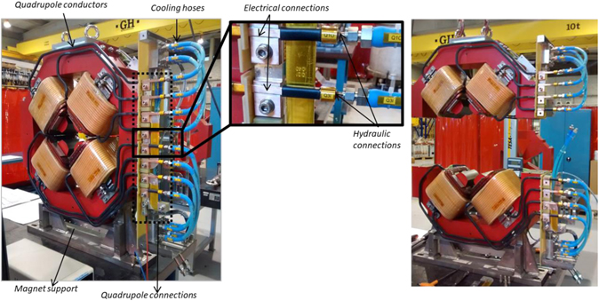
Figure 17. Left: front view of a complete magnet showing the connections of the quadrupole coils. The protection cover of the connection box has been removed. Center: detail of the connections. Right: magnet opened in two halves.
Download figure:
Standard image High-resolution image
Figure 18. Rear view of a complete magnet.
Download figure:
Standard image High-resolution imageConcerning instrumentation, each quadrupole coil is equipped with a thermal switch. The corrector coils have one thermal switch per electrical circuit. Each magnet has also a water flow switch, which due to the space requirements was installed at the water exit manifold, outside the magnet.
As specified (see section 3.3), a box in the lateral side of the magnet holds all the connections. It is protected by a polycarbonate cover and it has only one input and one output for electrical, hydraulic and thermal switch circuits of quadrupoles, horizontal and vertical steerers. This connection box is divided in two parts, to allow the magnet separation in upper and lower halves. It has been designed in such a way that the disassembly and reassembly can be done disconnecting a minimum number of components and without requiring any welding/un-welding operations. Pictures of this box in one of the magnets indicating the main elements are presented in figures 17 and 18.
Quadrupole coils are prolonged through long terminals conformed to reach the connection box, being their electric and hydraulic connections inside this box (see figure 17). For the hydraulic connection to the coil, a special bronze (CuSn12-C) piece was manufactured and brazed to the end of the coil terminal.
In contrast, as the corrector coils have no water cooling, their terminals are short and they are joined to cables which are guided to the connection box (an example can be seen in figure 18). The joint is performed with a copper tube crimped on both sides and soldered to the coil terminal.
All cables and connectors employed are compatible with the radiation requirements. The quadrupole coil terminals and the corrector connections are covered with heat shrinkable tube made of polyolefin, whose radiation resistance [19] was checked to be adequate for its use in LIPAc.
5. Acceptance tests
The magnets were subjected to tests at the factory to check their electrical, mechanical and cooling performance and to a thorough magnetic characterization. After that, they were shipped to CIEMAT premises where they were assembled with the rest of components of the HEBT line to check mechanical interferences and to define the best assembly procedure. These integration tests have been described in [6]. In the following, the factory and magnetic acceptance tests are described.
5.1. Tests at the factory
The reproducibility of the relative position of the quadrants after disassembling and new assembly of the magnets, as well as after exposing them to horizontal and vertical accelerations larger than those specified (0.4 g and 0.2 g respectively), was checked. This was done by measuring the distance between opposite poles and the clearance between adjacent poles with a vertical column (TESA-HITE 700). The vertical force needed for the test was achieved by lifting the magnets with the crane, and adding a weight equal to that of the magnet, while for testing of the response to horizontal forces, the magnet was tilted 37° around x and z axes.
The water circuit was checked performing pneumatic (He, 15 bar) and hydraulic (20 bar) tightness tests, demonstrating a pressure decrease of less than 2% after 3 h. The water pressure drop through the magnet was measured, showing increments higher than 10% with respect to the calculated values. This was attributed to the long terminals and intermediate connectors. The opening temperature of the thermal switches was recorded in tests similar to those performed for the individual coils, in which the magnet was energized without cooling.
The electrical properties: resistance, inductance and insulation impedance of the complete quadrupole and corrector magnets, were also measured. Resistance and inductance parameters were determined at 100 Hz and 1 kHz. Finally, a functional test feeding the quadrupole coils of the magnet continuously with the design (maximum) current was performed, both with 100% and 80% of the nominal cooling flow, and monitoring the outlet temperature. The flowswitch setpoints were defined on the basis of this test.
5.2. Magnetic tests
After passing successfully the Factory Acceptance Tests, the magnets were sent to the Magnetic Measurements Laboratory of the ALBA Synchrotron in Barcelona [20], for a full characterization of their generated magnetic field. The integrated fields of quadrupoles and correctors as well as the linearity and saturation characteristics were measured in a rotating coil bench [21]. Due to the large yoke apertures (see table 1) specific shafts with multilayer coils were produced to measure the field at the GFR (which has a radius of 34 mm in the case of the first triplet magnets and of 51 mm for the doublet and second triplet magnets). The two new shafts had diameters of 78 mm and 130 mm respectively. One of the quadrupoles was measured also using a Hall probe bench and a flipping coil bench, to gain confidence in the integrated field values obtained, which were in agreement within 0.1%.
To begin with, each magnet was aligned using a laser tracker against the rotating coil shaft by means of a movable support that holds the magnet during the test. The coordinates of the external fiducials with respect to the magnet mechanical center, obtained from the dimensional characterization of the yokes, were used for the positioning of the mechanical axis of the magnet in the center of the test bench. Figure 19 shows the magnet HMA07 in the bench, with the rotating coil shaft entering into the magnet aperture.
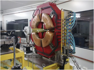
Figure 19. Magnet HMA07 on the rotating coil bench at ALBA magnetic laboratory with the new 130 mm diameter shaft. The global reference system is indicated.
Download figure:
Standard image High-resolution imageTable 8 shows the acceptance criteria of the magnets. Integrated quadrupole field, magnetic center deviation and quadrupole roll angle were measured at several currents up to the design (maximum) current Idesign (table 7). Measurements were performed both decreasing the current from Idesign down to 0 and increasing it back to Idesign. Before each transfer function measurement, the power supply was cycled four times between 0 and Idesign. All the magnets passed successfully the tests, fulfilling the acceptance criteria.
Figure 20 represents, for the eight quadrupoles, the measured transfer function for different current settings. The values of the transfer function have been normalized to those obtained at 50% Idesign. The iron saturation that takes place in the second triplet magnets for current values above 80% Idesign can be observed. The increase observed in the transfer function at low currents is an effect of the finite remanence of the iron yoke.

Figure 20. Measured transfer function (ratio between integrated magnetic field and current) for the HEBT quadrupoles, obtained ramping the current down from Idesign. To allow the representation of all magnets in the same graphic, the current values (abscissas) have been normalized to the maximum current of each magnet Idesign, and the ordinates have been normalized to those obtained at 50% Idesign.
Download figure:
Standard image High-resolution imageThe magnetic center deviation and the roll angle measured for the eight quadrupoles can be seen in figure 21.
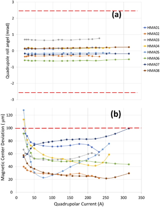
Figure 21. (a) Roll angle and (b) magnetic center deviation measured for the eight quadrupoles. The dashed lines mark the maximum acceptance values specified (table 8).
Download figure:
Standard image High-resolution imageQuadrupole field quality was characterized in all the current range in the case of the first triplet and doublet quadrupoles. For the second triplet magnets, the field quality was measured up to 0.8 Idesign, as the enhanced sensitivity of the new shafts led to the saturation of the acquisition integrators for higher values of the quadrupole excitation current. As expected, the manufacturing and quadrant positioning imperfections add some contribution to the harmonic content values, compared to those obtained from the electromagnetic simulations (table 4), but in all cases the harmonics are under the specified acceptance values (0.1% of the principal harmonic, equivalent to 10 units). Figure 22 shows the results corresponding to the 3 s triplet magnets which, as mentioned before, are the most difficult to manufacture with small tolerances and showed the largest dimensional deviations.
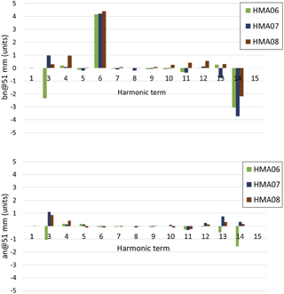
Figure 22. Measured quadrupole harmonics content for the second triplet magnets at 80% Idesign.
Download figure:
Standard image High-resolution imageRegarding correctors, table 9 summarizes the integrated field values obtained when feeding corrector coils at its maximum current, in two situations: with the quadrupole coils of the corresponding magnet at zero current and with these coils energized at the design (maximum) current. The measurements confirm a reduction of the corrector field when the quadrupole coils are energized at maximum current, with respect to the case of zero quadrupole current. This reduction, which amounts to 12%–28% depending on the magnet, being maximum for the second triplet magnets, agrees with the simulations (see figure 11) and is attributed to the saturation of the magnet yoke when quadrupole coils are active. In all cases, the corrector field at maximum current exceeds the 95% of the design (maximum) value (30 G m).
Table 9. Measured steerer field strength (G m) at 0.75rA.
| Quadrupole current | HMA01 | HMA03 | HMA04 | HMA05 | HMA06 | HMA08 |
|---|---|---|---|---|---|---|
| Vertical corrector | ||||||
| 0 | 34.9 ± 0.2 | 34.9 ± 0.2 | 35.8 ± 0.2 | 35.6 ± 0.2 | 40.7 ± 0.2 | 41.1 ± 0.1 |
| Idesign | 30.5 ± 0.2 | 30.5 ± 0.4 | 29.5 ± 0.7 | 29.8 ± 0.4 | 30.0 ± 1 | 29.9 ± 1 |
| Horizontal corrector | ||||||
| 0 | 35.8 ± 0.1 | 35.8 ± 0.1 | 37.7 ± 0.1 | 37.7 ± 0.1 | 41.2 ± 0.1 | 40.6 ± 0.2 |
| Idesign | 30.9 ± 1 | 31.0 ± 2 | 30.4 ± 0.6 | 30.7 ± 1 | 29.7 ± 1 | 29.8 ± 1 |
Measurements of the correctors harmonic content were carried out with the two sets of corrector coils powered at their maximum current (positive and negative), both individually and in combination with the main quadrupole coil. The results showed very good agreement with the simulation values (table 5). As an example, figure 23 shows the harmonics of the correctors of the second triplet, for the case of zero quadrupole current. It can be seen that harmonic amplitudes are below the limits specified in table 8. Similar results were obtained for the rest of correctors and for the case when all coils were powered.

Figure 23. Measured corrector harmonics content for the second triplet magnets (HMA06 and HMA08) at ±Idesign. Blue color is used for vertical correctors and green color for horizontal correctors.
Download figure:
Standard image High-resolution image6. Ancillaries
6.1. Cooling system
For the quadrupoles cooling, a cooling skid including all necessary elements (pump, valves, ionic interchange resins, expansion vessel and instrumentation among others) was arranged in a support frame. This system, which is intended to be installed outside the accelerator vault, provides cooling water with 1–1.5 μS cm−1 conductivity, maximum temperature of 31 °C and 16 bar maximum pressure in several branches in parallel to the three magnet groups as well as to other accelerator elements. This arrangement has the advantage of avoiding elements sensitive to radiation inside the accelerator vault and at the same time it allowed the performance of a very comprehensive test program at the manufacturer premises, thus minimizing the commissioning on-site work.
Inside the vault the materials were selected to withstand the radiation that will be present during accelerator operation (which is maximum near the accelerator axis). Stainless steel tubes with metallic connections were chosen. Plastic hoses are used only for some sections where flexibility is desirable or insulation is required: before and after the passage through the concrete wall of the accelerator vault, before and after entering an underground gutter as well as for the final distribution to the three or two magnets of each group.
6.2. Power converters
Independent power supplies have been provided for each quadrupole and corrector magnet with the specifications listed in table 10. Those feeding the magnets of each group are identical. Corrector power supplies are four-quadrant, so they are able to deliver positive and negative voltages and currents. All power sources are designed to ensure that in the event of a failure, the energy stored in the magnet is safely extracted.
Table 10. Power supply main specifications.
| Power supply type | Maximum range (A) | Maximum voltage (V) | Precision (±ppm of current setpoint) | Accuracy (% of the current setpoint) |
|---|---|---|---|---|
| First triplet quadrupole | 0 to 230 | 25 | <300 | 0.1 |
| Doublet quadrupole | 0 to 260 | 32 | <300 | 0.1 |
| Second triplet quadrupole | 0 to 320 | 58 | <300 | 0.1 |
| First triplet correctors | −21 to 21 | ±7 | <600 | 0.1 |
| Doublet correctors | −30 to 30 | ±10 | <600 | 0.1 |
| Second triplet correctors | −17 to 17 | ±9 | <600 | 0.1 |
At the LIPAC site the power supplies are located outside the accelerator vault. 150 mm2 and 25 mm2 copper section cables with a length of 80–90 m are used to connect the quadrupole and steerer coils to their power supplies. The cables enter the vault through a pit below the concrete wall that surrounds the accelerator vault.
The maximum voltage specified for each power supply takes into account the voltage drop at the magnet at the design (maximum) current plus that needed during the current rise, and considers also the voltage drop at the cables (which due to the cable length required, can be up to 25% of the voltage at the magnet terminals) plus an additional 20% margin.
It is important to highlight the demanding level of precision required for these power supplies and, in particular, for those of the quadrupoles. These stringent requirements arise from the beam dynamics error analysis of the HEBT line (table 2). The required precision is always referred to the current setpoint (not to the maximum value) and includes any deviation of the current from the reference value due to any cause (among others, long-term stability, ripple or temperature deviations).
The power supplies were manufactured by Sigmaphi Electronics (presently JEMA France), using commercial switch-mode power supplies which were adapted to the specific requirements. For the quadrupoles of the second triplet, two commercial power supplies in series are used in order to obtain the necessary voltage. Quadrupole power supplies are water cooled whereas steerer power supplies are air cooled. All power supplies have been installed in three cabinets (figure 24).

Figure 24. The three cabinets containing the power supplies during the factory tests.
Download figure:
Standard image High-resolution imageThe power supplies underwent successful acceptance tests at the factory, first with a test load, and afterward with the LIPAc HEBT magnets, for the validation of their dynamic response and fine tuning of regulation parameters. A comprehensive testing program was carried out for each of them including, among others, insulation tests, ripple and precision measurements, current stability tests and interlock tests.
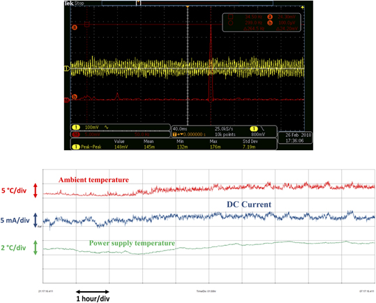
As an example, figure 25 (top) shows the voltage ripple (yellow line) at the output of the 2nd triplet quadrupole power supply. This measurement was obtained during the tests at the factory, with the power supply providing 320 A to its corresponding magnet. Fast Fourier transform (red line) of the voltage ripple was used to identify the first significant frequency to calculate the value of the current ripple. In the test shown in the figure, the first significant frequency is around 300 Hz and the current ripple value obtained from the calculation is less than 3 ppm.
Figure 25. Results from factory acceptance tests of the power supplies. Top: voltage ripple and its FFT during tests at factory. Second triplet quadrupole power supply connected to the magnet. Bottom: long-term current stability test performed at factory with the power supply (first triplet quadrupole) at maximum current connected to a dummy load.
Download figure:
Standard image High-resolution image
All power supplies have been tested at maximum current for at least 8 h in order to check the long-term current stability. Figure 25 (bottom) shows the result of this test performed on a 1st triplet quadrupole power supply providing 230 A to a dummy load during 10 h. The blue line represents the DC current with a high magnification, to check the stability at the mA level. The red and green lines are respectively the ambient temperature and the internal temperature of the power supply. The maximum variation of the current during the whole test is less than 7 mA, which corresponds to about 30 ppm (well below the required value).
7. Conclusions
The design, manufacturing and tests of the quadrupole and corrector magnets for the LIPAc accelerator HEBT line have been presented. The magnets were validated successfully before shipping them to the LIPAc site at Rokkasho (Japan). Many lessons were learned during the development of the different activities. These may be useful for future neutron source facilities such as DONES [22], F-ANS [23] or other installations involving accelerators with similar requirements. The main conclusions and lessons learned are the following:
Regarding magnetic design:
- The combination of quadrupole and corrector magnets in the same iron yoke has shown to be feasible and adequate for the use in transport lines of linear accelerators with space constraints such as LIPAc. The high sextupolar component of the resultant steerer field has been shown to have negligible effect on the particle trajectories.
- The steerer current needed for a given correction depends on the quadrupole field. This quadrupole–corrector coupling effect is due to the iron saturation, being higher for high quadrupole currents and specially for the second triplet magnets. Both simulations and experimental measurements show that the corrector current must be increased up to 38% due to this effect.
Regarding coils design and manufacture:
- It is better to try to use the same conductor, if possible, for all magnets, in order to ease the procurement of raw material and the coil manufacturing.
- If a mass insulation test with the coils immersed in water is foreseen, vacuum pressure impregnation techniques must be employed instead of simpler solutions like pre-preg.
- Quadrupole coils impregnation: with the aim of obtaining the design geometry the mold was manufactured with small margins. A fraction of the coils had to be discarded because after impregnation they presented dry regions, with low resin content. The mold design was modified leaving larger margins for a correct resin circulation.
About yoke manufacture:
- The 3D measurements performed showed some deviations in the pole profile with the z coordinate, which are attributed to wire bending during machining of the thickest yokes. As this error is the same in all quadrants, its effect on the magnetic field is small, and the magnetic measurements showed a quadrupole performance within specifications.
- Small plane regions machined at the pole corners allow precise measurements of the distance between adjacent poles, which are very useful to check, with simple instrumentation, the correct assembly of the quadrants and of the magnet halves.
Other lessons with respect to layout and assembly:
- There were difficulties to introduce the coils in the yokes, because of the higher fiberglass thickness at the inner corners. It was necessary to make some small chamfers in the iron to allow the assembly and right positioning of the coils.
- During the magnet testing, changes of the insulation impedance between the quadrupole coils and the iron yoke were observed, which were attributed to humidity absorption by the solid pieces of insulator surrounding the electrical connections (see figure 17). The material used for these pieces was G10, which is extensively used in magnet manufacture; however, it was found that humidity could deteriorate its insulation capability. A large margin in the insulator thickness, the control of the environmental humidity and periodic checks of the impedance during magnet operation are recommended.
- Flow switches were in principle intended inside the volume reserved for the connections at the lateral side of the magnets. As this was not possible due to lack of space, they were placed close to the magnet water outlet, on the general support frame.
- The requirement of making electrical and hydraulic connections at the magnet lateral side, motivated by the radiation environment as explained in section 3.3, led to very long terminals of the quadrupole coils which complicated their impregnation and handling. However, additional advantages of this solution, leading to an increased free space between magnets, were confirmed during integration tests of the quadrupole groups with the beam tubes, diagnostics and supports [6]. The design performed will contribute to reduce the time required for maintenance operations close to the beam tube, where the residual radiation field is maximum.
Disclaimer
This work was undertaken under the Broader Approach Agreement between the European Atomic Energy Community and the Government of Japan. The views and opinions expressed herein do not necessarily state or reflect those of the Parties to this Agreement.
Acknowledgments
This work has been supported by the Spanish Government in the frame of the Broader Approach Agreement (Spanish Boletín Oficial del Estado No. 14, from 16th January 2013 p 1988).
Footnotes
- 6
Throughout the paper, the harmonic content of the magnetic field is expressed in terms of coefficients normalized to the fundamental mode (B2 in the case of quadrupoles, A1 for horizontal correctors, B1 for vertical correctors), being bn and an the normal and skew multipoles of order n. 1 unit means a harmonic amplitude of 10−4 that of the fundamental mode.