


Abstract
Mitigation of deleterious heat flux from edge-localized modes (ELMs) on fusion reactors is often attempted with 3D perturbations of the confining magnetic fields. However, the established technique of resonant magnetic perturbations (RMPs) also degrades plasma performance, complicating implementation on future fusion reactors. In this paper, we introduce an adaptive real-time control scheme on the KSTAR tokamak as a viable approach to achieve an ELM-free state and simultaneously recover high-confinement (βN ∼ 1.91, βp ∼ 1.53, and H98 ∼ 0.9), demonstrating successful handling of a volatile complex system through adaptive measures. We show that, by exploiting a salient hysteresis process to adaptively minimize the RMP strength, stable ELM suppression can be achieved while actively encouraging confinement recovery. This is made possible by a self-organized transport response in the plasma edge which reinforces the confinement improvement through a widening of the ion temperature pedestal and promotes control stability, in contrast to the deteriorating effect on performance observed in standard RMP experiments. These results establish the real-time approach as an up-and-coming solution toward an optimized ELM-free state, which is an important step for the operation of ITER and reactor-grade tokamak plasmas.
Export citation and abstract BibTeX RIS
1. Introduction
When sufficiently heated, magnetically confined tokamak plasmas spontaneously transition to a high confinement mode (H-mode) [1]—a promising plasma operation scenario for future fusion power plants. The H-mode is characterized by a narrow edge transport barrier concomitant with the formation of an edge pedestal with a steep pressure gradient. This 'pedestal' not only enhances performance in the core region but also increases the non-inductive current, improving the fusion economy by reducing the external heating and recirculating power required for steady-state operation. Because of these advantages, the ITER baseline scenario [2] plans to utilize H-mode plasmas to demonstrate burning plasma in a tokamak for the first time. However, H-mode also presents serious risks to reactor operation, most prominently through the creation of dangerous edge instabilities called edge localized modes (ELMs) [3]. These rapid relaxations of the pedestal density and temperature result in intense transient heat fluxes on the reactor walls, leading to undesired material erosion and surface melting which will not be acceptable in a reactor scenario [4, 5]. Therefore, to retain the tokamak design as a viable option for fusion reactors, it is critical that we develop methods to routinely suppress ELM events without degrading the plasma performance.
One of the most effective methods to control ELMs is to apply resonant magnetic perturbations (RMPs) using 3D coils [6–9]. RMPs suppress ELMs by causing additional transport [10–23] in the pedestal, degrading its height to a point where ELMs are no longer unstable [24–26]. However, this inevitably comes at the considerable expense of global confinement deterioration, decreased access to high-performance plasma regimes and thus depleted economic prospects. This degradation tends to be greater with a lower toroidal wave number (n) of RMP. Even so, the use of low-n configurations will be important at the reactor level due to the strong decay of external fields in the thick shielding between the plasma and field coils. Undoubtedly, the compatibility of RMP ELM suppression with high confinement operation requires urgent exploration.
In this context, we report on an adaptive RMP scheme capable of maximizing plasma performance while maintaining robust ELM suppression. With this new technique, up to ∼60% of the RMP-induced performance degradation can be quickly recovered, returning the plasma to a high-power state suitable for future reactors. By exploiting a salient hysteresis process on the KSTAR tokamak [27], we find that RMP-induced transport does not just produce a negative influence on confinement (as is typically assumed) but instead also opens up a pathway to strong recovery of plasma performance that is accessible to a highly-optimized controller. This leads to the concurrent establishment of high confinement plasmas and sustained ELM suppression at normalized performance close to the ITER-baseline level, reaching βN ∼ 1.91, βp ∼ 1.53, and H98 ∼ 0.9. Here,  is the normalized beta,
  is the poloidal beta, and H98 = τexp/τ98 is the thermal energy confinement quality compared to the standard H-mode plasmas, where p is the averaged plasma pressure, a is the minor radius, Ip is the total plasma current, BT is the toroidal magnetic field, Bp is the poloidal magnetic field, B is the total magnetic field, τexp is the experimental thermal energy confinement time, and τ98 is the empirically derived confinement time using standard H-mode database [28]. Since H98 enters to the power of 3.23 in determining the fusion gain Qfus [29], where Qfus is the ratio between produced fusion energy over input, the strong recovery of H98 demonstrated in this work allows a substantial reduction of fusion cost, establishing a means with which RMPs can be used for ELM suppression to enable commercial-grade fusion devices.
In this paper, the descriptions of the adaptive scheme and experimental results are given in section 1. Section 2 describes its advantage in terms of achieving safe ELM suppression by avoiding mode locking. In section 3, the widened ion temperature pedestal during ELM-free state and its effect on the performance recovery are presented, respectively. A possible mechanism of ion temperature pedestal widening is also discussed in following section. Lastly, conclusions are drawn in section 5.
2. Optimized ELM-free state by adaptive scheme
2.1. ELM suppression using adaptive RMP amplitude control
The real-time adaptive approach in this study detects ELMs from a Dα emission measurement and finds the optimum RMP strength or coil current IRMP sufficient to maintain the ELM-free state while small enough to maximize the confinement. The adaptive ELM control experiment (#26004) in KSTAR introduced here is outlined in figure 1. Figure 1 shows a H-mode plasma with fully suppressed ELMs via adaptive feedback RMP amplitude control. The relevant plasma parameters are plasma major radius R0 = 1.8 m, minor radius a0 = 0.45 m, the toroidal magnetic field BT = 1.8 T at major radius R0, Greenwald density fraction nG ∼ 0.4, elongation κ ∼ 1.71, upper triangularity δup ∼ 0.37, lower triangularity δlow ∼ 0.85, and pedestal collisionality νe, ped∼0.5. In this discharge, a hysteresis effect is utilized where ELM suppression can be maintained over long periods with a lower RMP strength than initially required for access to the ELM suppression regime [17]. Because reduction of the RMP amplitude leads to an increased pressure pedestal height, this enables global confinement recovery in an ELM-free state [30] by adjusting RMP levels. To avoid ELMs while maximizing the confinement, we use a pre-programmed low n = 1 RMP spectrum [8] with 90 degree phasing and apply real-time feedback to control its amplitude. During the plasma current flattop before applying RMP, with Ip = 0.51 MA and ∼3 MW of co-neutral beam injection heating, βN ∼ 2.13, βp ∼ 1.71, and H98 ∼ 1.03, close to the targets of the proposed ITER baseline scenario. In this discharge, the plasma edge safety factor q95 ∼ 5, which is higher than the target value of q95 ∼ 3. Here, q95 is defined as the pitch of the magnetic field line in the edge where the normalized poloidal flux (ψN) is 95%. However, after achieving the first stable ELM suppression through traditional means (7.1 s), the plasma performance significantly decreases to βN ∼ 1.62, βp ∼ 1.30, and H98 ∼ 0.68. The 30% reduction in overall confinement by RMP mainly comes from degradation in density and temperature pedestal, as shown in figures 1(c) and (d). Such extensive confinement and H98 degradation is a well-known general trend in low-n RMP experiments [31–33] and will not be acceptable in a future fusion reactor because this leads to a significant increase in fusion cost.

Figure 1. Time traces of discharge #26004 with adaptive ELM control using n = 1 RMP (#26004) with adaptive RMP control. (a) RMP coil current IRMP (blue), Dα emission (green) near outer divertor target, and detected ELM frequency fELM (red). (b) Plasma confinement scaling H98 (blue), normalized beta βN (green), and poloidal beta βp (red). (c) Pedestal height of ion Ti, ped (blue), electron Te, ped (red) temperature, and NBI heating power PNBI (green). (d) Pedestal height of electron density ne, ped (blue) and toroidal rotation Vϕ,ped of carbon (6+) impurity in co-Ip direction (red).
Download figure:
Standard image High-resolution imageAfter this initial degradation, the real-time adaptive ELM control scheme starts to recover the original performance before RMPs were introduced while maintaining stable ELM suppression. The controller leverages the Dα emission signal near the outer divertor target to calculate the frequency of ELMs (fELM) [34] in real-time and change IRMP accordingly. To achieve ELM suppression, the RMP amplitude (or coil current, IRMP) is raised until fELM decreases to 0, i.e. ELM suppression. Then, during the resulting ELM-free period, the controller lowers the RMP strength to raise the pedestal height until ELMs reappear, at which point the control again starts to ramp up the RMP amplitude until suppression is recovered (figure 1(a)). In the experiment presented in figure 1, there are 0.5 s of RMP flattop intervals between the RMP-ramp up and down phase to achieve saturated RMP response. Throughout this process, we adjust the lower bound of IRMP to slightly higher value (by 0.1 kA) than where the most recent ELM returns. This adaptive constraint reduces the likelihood of ELM suppression loss and control oscillation. The feedback system leads the plasma to a converged operating point that optimizes both ELM-free operation and confinement, recovering most of the performance lost in the initial application of RMP.
In the selected discharge, this adaptive ELM control scheme achieves a stable ELM-free phase at 10.5 s with recovered global confinement, as shown in figure 1(b). Although a few ELMs occur before convergence, the controller successfully reaches a stable operating point with minimized ELMy periods. In the final state, the plasma performance shows βN ∼ 1.91, βp ∼ 1.53, and H98 ∼ 0.9, recovering up to 68% of the original confinement degradation. Such increase in H98 is especially important as this leads to the 60% recovery in Qfus degradation, thus emphasizing the performance of adaptive control.
2.2. Recovery of pedestal height by adaptive RMP control
The enhanced confinement quality by adaptive RMP control occurs with the recovery of both the temperature and density pedestals. For the profile reconstruction, ion temperature is measured by charge exchange recombination system [35] for carbon (6+) impurities at outboard mid-plane. Electron temperature is measured by the Thomson scattering [36] and electron cyclotron emission [37] system. Core electron density is measured by the Thomson scattering and two-color interferometry system [38]. To obtain well-resolved profiles, the data are averaged over 100 ms. The pedestal height is obtained from hyperbolic tangent fits with edge profiles, where its location depends on the pedestal width. The equilibria from EFIT code [39] is used for the radial profile mapping and fitting. Kinetic equilibria are reconstructed for the plasma detailed analysis. This equilibrium is calculated with the pressure profile (summation of thermal pressure profile from radial profile reconstruction and fast ion pressure from NUBEAM code [40]) and current density profile (core current from motional Stark effect diagnostics [41] and edge current using NUBEAM, Ohmic and Sauter current models [42]) as a constraint. Figures 1(c) and (d) shows the time traces of fitted pedestal heights for all channels. As can be seen in the figure, all pedestals are significantly improved from the first ELM suppression phase (7.1 s). For example, electron (Te, ped) and ion (Ti, ped) temperature pedestals increase by 22% and 50%, respectively. In addition, the electron density pedestal (ne, ped) is also recovered by 10% at the same time. Interestingly, H98 ∼ 0.9 at 10.5 s is much larger than H98 ∼ 0.75 at 6.2 s, even with the same IRMP = 3.6 kA. This indicates that the confinement recovery by adaptive approach is not solely attributable to decreased IRMP, but rather that another contributor leads the plasma to a reinforced recovery to the high-confinement state.
We note that the ion temperature pedestal exhibits significant recovery compared to the other channels. This is mainly due to the rapid and significant increase of ion temperature pedestal height by decreasing RMP strength. The traces of pedestal height versus IRMP before the first ELM reappearance (5.3–7.7 s) reveal this trend. Figure 2 shows the changes of ion, electron temperature and electron density with respect to the IRMP during 5.3–7.7 s. In the figure, ne, ped and Te, ped have a similar dependence on IRMP during the pedestal degradation (5.3–6.5 s) and recovery (7.1–7.7 s) phases, showing  and
and  . However, Ti, ped in the recovery phase shows a 50% larger response of −0.09 eV A−1 compared to the degradation phase, −0.06 eV A−1. The difference of responses in these phases leads to the faster and larger recovery of the ion temperature pedestal. Here, figure 2(d) shows that βp exhibits similar trend with Ti, ped, where
  in the recovery phase has a 50% larger response of −0.14 kA compared to the degradation phase, −0.07 kA. Because such a boosted response of βp leads to the reinforced confinement recovery, this similarities between Ti, ped and βp responses indicates that Ti, ped dynamic can be considered as a key to the successful confinement optimization via adaptive RMP control.
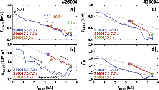
Figure 2. Pedestal heights and global confinement for RMP ramp-up (5.3–7.1 s, blue), down (7.1–7.7 s, red), first saturated ELM-suppression (7.1 s, green), first optimized suppression (7.7 s, purple), and finally optimized suppression (10.5 s, orange). Pedestal height of (a) electron temperature Te, ped, (b) electron density ne, ped and (c) ion temperature Ti, ped. (d) Global poloidal beta βp. Ion temperature is measured by a charge-exchange recombination system for carbon (6+) impurities. Electron temperature is measured by the Thomson scattering and electron cyclotron emission system. Electron density is measured by the Thomson scattering and two-color interferometry system.
Download figure:
Standard image High-resolution imageIn addition to the changes of pedestal heights, the radial profiles during discharges are compared. Figure 3 illustrates the radial profiles of ion, electron temperature, and density at three important time slices during the recovery phase; first saturated ELM suppression state (7.1 s), first optimized ELM suppression state (7.7 s), and finally converged state (10.5 s). As shown in figures 3(a)–(c), all radial profiles in the core plasma are almost identical during the recovery phase. Therefore, the improved confinement by decreasing RMP strength results from increased ne, ped, Te, ped, and Ti, ped, with the last one dominant. Here, the statistical error bars of ne, ped, Te, ped, and Ti, ped are ∼12%, ∼11%, and ∼5%, respectively. It turns out that ∼67% of improvement comes from the ion temperature pedestal, while the contribution of ne, ped and Te, ped to the confinement recovery is 20% and 13% respectively. In this respect, the recovery of Ti, ped is responsible for reinforced recovery by adaptive control. The large growth of Ti, ped is mainly due to the simultaneously increased upper limit of Ti, ped before the loss of ELM suppression and its enhanced response to the RMP strength. In addition, ne, ped shows a large increase near IRMP ∼ 5 kA (figure 2(b)), which can be attributed to reduced particle pumping from ELMs. This occurs before 7 s and does not directly contribute to confinement recovery beginning at 7.1 s. However, it still strengthens the confinement recovery with increasing Ti, ped. Given that the profiles of 7.7 s and 10.5 s are very similar, control iterations after 7.7 s can be considered as a repeated cycles similar to first ELM suppression period (5.3–7.7 s) for the control convergence. Therefore, the following analysis is focused on the first control iteration for easier explanation.
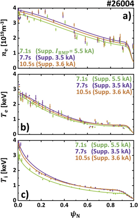
Figure 3. Radial profiles for first saturated ELM-suppression (7.1 s, green), first optimized suppression (7.7 s, purple), and finally optimized suppression (10.5 s, orange). (a) Electron density, (b) electron temperature and (c) ion temperature with statistical error bars. Ion temperature is measured by a charge-exchange recombination system for carbon (6+) impurities. Electron temperature is measured by the Thomson scattering and electron cyclotron emission system. Electron density is measured by the Thomson scattering and two-color interferometry system.
Download figure:
Standard image High-resolution image3. Achieving safe ELM suppression with adaptive control
In standard H-mode discharges, strong RMPs are favorable for entering the ELM suppression but also raises the possibility of dangerous plasma destabilization. Too large of an RMP field in the core plasma normally leads to a locking of plasma rotation and invokes a disastrous core instability called a disruption. Figure 4(a) shows the adjacent discharge (#26014) whose RMP-induced locking occurs at 10 s with sudden drop of plasma confinement (βN). This core locking (or disruptions) terminates the plasma and forms transient heat fluxes on the tokamak walls which are even more severe than ELMs. Unfortunately, plasma disruption is easier with low-n RMPs. Therefore it is vital to maintain the RMP strength between the thresholds of ELM suppression and disruption. To complicate this process, these thresholds change in time with various plasma parameters and are often hard to theoretically predict. The database [33] for n = 1 RMP ELM suppression in KSTAR reveals broadly scattered experimental thresholds showing 1–2 kA variations, and empirical prediction is also challenging due to their sensitivity to plasma parameters. For these reasons, in the present experiments, a series of discharges are used to find safe RMP strength for ELM suppression. This approach will not be applicable in a fusion reactor, where a single disruption can result in the termination of machine life.
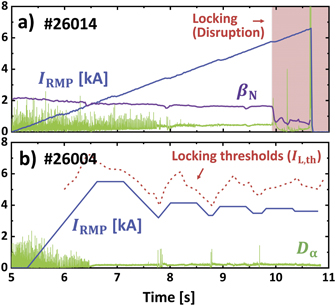
Figure 4. Time traces of RMP-induced locking and suppression discharge with n = 1 RMP in KSTAR. (a) RMP coil current (blue), Dα emission (green), and βN (purple) of discharge #26014. Onset of locking (disruption) is marked as a red region. (b) RMP coil current (blue) and Dα emission (green) of discharge #26004. The locking thresholds in IRMP is marked as a red dotted line.
Download figure:
Standard image High-resolution imageNotably, the adaptive approach lowers the RMP strength after entering the ELM-free state and maintains it near the levels for marginally stable ELM suppression. This automatically avoids touching the disruptive limits. Previous study [43] revealed that the locking occurs when perturbed field at core region (δBr, core) exceeds the certain limit. This study calculates the perturbed radial fields (δBr) by RMP using the ideal plasma response code, IPEC [44], with given magnetic equilibria and IRMP. The core responses δBr, core is derived off-line through radially averaging δBr at ψN = 0–0.9. Based on the calculated response, the empirical δBr, core threshold for core-locking is obtained from neighboring discharge (#26014) as  . The predicted locking thresholds (IL,th) in IRMP are equivalent to the δBr thresholds based on the ideal plasma response calculation. As shown in figure 4(b), the RMP strength in the adaptive RMP discharge (#26004) stays safely below the IL,th threshold throughout the example discharge, highlighting the advantages of this adaptive scheme for achieving stable ELM suppression. Here, the IL,th exhibits similar trend with IRMP because δBr, core increases with βN even with the same applied field strength. Although adaptive RMP control will be ineffective if only a small margin exists between the thresholds for suppression and disruption, it still reduces the necessity of extensive optimization of the RMP geometry for locking avoidance, which often comes at the expense of other important parameters or operational degrees of freedom.
4. Ion temperature pedestal broadening and adaptive ELM control
4.1. Improved ELM stability and ion temperature pedestal response by ion-pedestal widening
As mentioned earlier, the RMP induces additional transport process in the edge region, resulting the degradation of pedestal height and its gradient. However, RMP-induced pedestal transport can also facilitate the improvement of the Ti, ped upper limit in the ELM-free phase and its response to the RMP strength by broadening the ion temperature pedestal. Effect of RMP-induced transport on the ion temperature pedestal can be found from the analysis of the profiles in detail. Figures 5(a) and (b) illustrate ion temperature pedestal and E × B flow (ωE) profiles for five times between 5.3 and 7.7 s. Before ELM suppression (5.3–6.3 s), Ti, ped decreases with IRMP, while the pedestal gradient is well sustained (or even slightly increased). After ELM suppression (>6.5 s), however, the pedestal gradient starts to change. The transition from 6.6 to 7.1 s shows broadening of the ion temperature pedestal and decreasing of its gradient. This widening is maintained in the pedestal recovery phase up to 7.7 s. The decrease in pedestal height and gradient are both due to RMP-induced transport. However, the rapid broadening of the ion temperature pedestal after ELM suppression indicates that its gradient is not governed by the transport affecting the pedestal height but instead by an 'additional' transport source that occurs in the ELM suppression phase. For example, reduced ωE profiles and its gradient with ion temperature pedestal broadening may indicate the change of turbulence and neoclassical transport, which is known to increase with smaller E × B well at the pedestal region [45, 46].

Figure 5. Time traces of pedestal profiles during adaptive ELM control (#26004). (a) Ion temperature pedestal profiles with statistical error bars are shown for five different time slices. (b) E × B flow profiles (ωE) at pedestal are shown for five different time slices.
Download figure:
Standard image High-resolution imageThe change in ion temperature pedestal width improves the ELM stability. In theory, pedestal pressure (Pped) or pedestal poloidal beta ( ) should stay under the stability limit to avoid the reappearance of ELM crashes. Although it is not yet theoretically revealed how low βp, ped should be than this limit, the stability analysis confirms that experimental βp, ped stays below
  of the stability limit during the ELM suppression phase. Therefore, in this work, we assumes the ELM suppression can be maintained under the 70% of βp, ped limit imposed by stability constraint. Here, the pedestal stability is predicted using ideal peeling-ballooning (PBM) theory [3] and the EPED1 [47] algorithm. The fixed-boundary equilibrium code, CHEASE [48], is used for accurate equilibrium mapping, and the ideal MHD stability code, MISHKA1 [49], is employed for PBM stability calculation. All other required parameters are taken from the reconstructed radial profiles and plasma equilibrium.
This stability limit is known to improve with increased pedestal width [50]. Therefore, widened pressure pedestal via ion-pedestal broadening allows for higher βp, ped during the ELM-free phase. Numerical analysis reveals that the βp, ped limit increases by 53% due to ion temperature pedestal broadening. This change is presented in figure 6. In the figure, βp, ped limits derived with (orange) and without (gray) broadened ion temperature pedestal are presented with experimental points (magenta). It can be seen that the limit is enhanced by pedestal widening. With the expansion of the βp, ped limit illustrated as dotted lines, βp, ped can further increase from 0.2 (gray dotted line) to 0.31 (orange dotted line). This enhanced βp, ped limit allows access to higher Ti, ped in the ELM suppression phase. For example, ELM suppression can be maintained at 7.7 s where Ti, ped = 0.7 keV, which is higher than 0.6 keV in ELMy phase (6.3 s), as shown in figure 2(c).
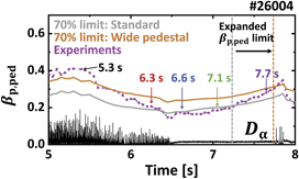
Figure 6. Time traces of pedestal stability limits during adaptive ELM control (#26004). (a) Ion temperature pedestal profiles with statistical error bars are shown for five different time slices. 70% of ELM stability limit for βp, ped with (orange) and without (gray) wide ion temperature pedestal, calculated from EPED code. Experimentally measured βp, ped (magenta) and Dα emission (black) are also shown. The dotted lines show βp, ped limits during ELM-free state imposed by pedestal stability with (orange) and without (gray) wide ion temperature pedestal.
Download figure:
Standard image High-resolution imageThe broader ion-pedestal also can lead to a larger response of Ti, ped on RMP strength. Inspired from (Hu et al 2020) [51], the change of temperature pedestal height (ΔTped) by ΔIRMP and magnetic islands can be described as equation (1),

where Wm, n
and ∇Tped are the (m, n) island width and pedestal gradient, respectively. qped is the edge safety factor on the pedestal top. This expression is based on the concept where the contribution of an island on the pedestal degradation (ΔTped) by RMP is the accumulation of profile flattening at the islands in the pedestal region. We note that constant ∇Tped over the pedestal region is assumed to make interpretation easier. This expression addresses that pedestal height changes more rapidly with RMP strength as the pedestal gradient grows and qped decreases. With the given q profile monotonic, qped is reduced by increasing pedestal width. Because the summation term (∑) increases with qped and width, the broadened ion temperature pedestal can lead to a stronger response of Ti, ped despite the decrease of ion temperature pedestal gradient (∇Tped). In addition, ion temperature pedestal is known to be heavily influenced by neoclassical transport [15, 46, 52]. Here, RMP can increase the neoclassical heat flux and the amount is roughly proportional to the square of perturbed field strength and  . Smaller edge E × B can increase the sensitivity of ion heat flux to RMP strength [53, 54]. Because a decreased ion temperature pedestal gradient reduces the ωE [19, 55] at the pedestal (figure 5(b)), this change in radial electric field also contributes to increasing the response of Ti, ped.
On the other hand, the responses of ne, ped and Te, ped to RMP strength are almost identical whether or not the ELMs are fully suppressed. This means that additional RMP-induced transport in the ELM-free phase has a smaller effect on the electron density and temperature pedestal gradient. Although the electron pedestal width has considerable uncertainty due to limitations in the resolution of edge diagnostics, its value lies between 4%–6% in normalized poloidal flux without showing a considerable widening like ion temperature pedestal, suggesting that additional transport has only a relatively small effect on electron channels. We note that a large decrease in electron pedestal height still occurs without a clear change in its width, and this additional transport is expected to have little correlation with 'pump-out' commonly observed in RMP experiments.
4.2. Advantages of wide ion temperature pedestal in adaptive ELM control
Increased Ti, ped response by RMP-induced transport leads to an extensive recovery of Ti, ped during RMP ramp-down and makes an ion temperature pedestal higher than the RMP ramp-up phase (ELMy) even with the same RMP strength. In addition, enhanced pedestal stability allows for larger Ti, ped before the return of ELMs. The synergy between these effects boosts the pedestal recovery and enables adaptive control to maximize the confinement, resulting in a much higher pedestal than during the initial phase of ELM suppression, as shown in figure 7, which illustrates βp, ped versus IRMP. The changes to the pedestal from 5.3 to 7.8 s are shown, and the ELM suppressed states are marked with star points.
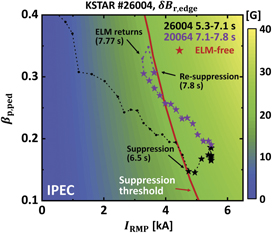
Figure 7. The pressure pedestal height βp, ped versus RMP strength during adaptive ELM control (#26004). The time traces of βp, ped in #26004 discharge for 5.3–7.1 s (black) and 7.1–7.8 s (purple) with varying IRMP. ELM-free states are marked as star dots. Contours of δBr at pedestal region from ideal response calculation using IPEC are also shown. Experimentally derived δBr, edge threshold for ELM suppression is drawn as a red curve.
Download figure:
Standard image High-resolution imageAnother advantage of RMP-induced transport is that it improves the control stability. Adaptive control can be unstable due to a bifurcation of the plasma state during transitions between ELMy and ELM-free regimes, which causes oscillation of the control system. In particular, it can take a long time or even become impossible for a controller to find the optimal solution because of the sudden jump in RMP strength required for re-entry (IIN) to or exit (IOUT) from ELM suppression. The schematic diagram in figure 8(a) illustrates how this characteristic will delay the control convergence. In practice, ELM control must be done quickly to minimize damage to the reactor, so an adaptive approach is generally hard to use in such a bifurcating system. However, RMP-induced transport eases these control difficulties by reducing IIN during adaptive control, as shown in figure 8(b).

Figure 8. Schematic diagram of adaptive ELM control using RMPs. Here, RMP threshold for ELM suppression entry (IIN, orange) and exit (IOUT, gray) are drawn. Time trace of IRMP (green) and onset of ELMs (red box) are also shown. Expected time trace of adaptive ELM control with (a) constant IIN and (b) decreasing IIN in time.
Download figure:
Standard image High-resolution imageIt has been shown that the plasma enters the ELM suppression state above a certain δBr, edge threshold [43], where δBr, edge is the perturbed radial field strength at the pedestal. Again, δBr, edge is calculated using IPEC code [44] and derived through radially averaging δBr at ψN = 0.9–1.0. The thresholds of δBr for RMP-induced ELM suppression is obtained from the reference discharge (#26004). This threshold (∼20 G) is shown as the red contour of figure 7. Here, βp, ped amplifies the perturbed field [43], and the same δBr can be obtained with a smaller IRMP with larger βp, ped. Because RMP-induced transport enhances βp, ped in an ELM-free state, this leads to a lower IIN, making access to the next ELM suppression regime easier. The ELM suppression of 7.8 s shown in figure 7 results from reduced IIN compared to the former one at 6.5 s. Thus, IIN for each suppression entry changes as 4.9 → 3.6 → 3.53 → 3.5 kA, as seen in figure 1(a), resulting in fast and stable system optimization. This interesting example shows uncommon positive effect [56, 57] of self-organized transport on pedestal confinement.
We note that such an RMP-induced hysteresis shown in figure 7 is not trivial to be produced in the experiment as it conventionally requires a delicate pre-programmed RMP waveform under the absence of real-time control. This leads to difficulties in investigating and exploiting the hysteresis, which is critical to optimize the ELM-free state. In this respect, adaptive RMP control is an effective methodology as it can automatically generate the hysteresis and utilize it. In addition, the adaptive scheme has been successfully operated for more than a 100 confinement times ( s) of KSTAR, and therefore, this control is also expected to be applicable to long pulse plasma in ITER.
4.3. The RMP-induced transport and broadened ion-pedestal
It is worth pointing out that successful adaptive control in these experiments is mainly due to a broadened ion temperature pedestal during the ELM suppression phase. In order to determine the change in ion heat transport, interpretive transport analysis is conducted using ASTRA 7 [58] code. The ion neoclassical heat diffusivity (χi, neo) is also calculated based on NCLASS [53] model to compare it with experimental ion heat diffusivity (χi). The results are shown in figure 9, where χi (a) and χi, neo (b) for 5.3–7.7 s are included. As shown in figure 9(a), the ion heat diffusivity (χi) of the pedestal region rapidly increases via additional transport after transitions to the ELM-free state. In addition, the pedestal heat diffusivity does not change much during 7.1–7.7 s, indicating that it is insensitive to the decreasing IRMP. It has been reported that the neoclassical transport effect dominates ion heat transport under RMPs [46, 52]. However, this collisional transport strongly depends on the RMP strength. Therefore, the broadened ion temperature pedestal does not seem to be related to the neoclassical process. Here, it can be seen in figure 9(b) that χi at 5.3 s (gray) exceeds neoclassical level in all cases, supporting the existence of additional transport. We note that following analyses will focus on the center region of the pedestal (ψN = 0.96), where the change in ion heat diffusivity is clearly observed in time.
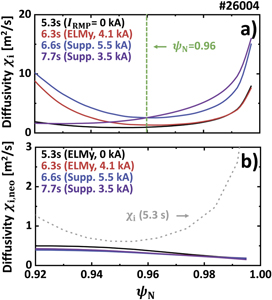
Figure 9. The radial profiles of (a) experimental ion heat diffusivity (χi) and (b) theoretical ion neoclassical heat diffusivity (χi, neo) for four different time slices including 5.3, 6.3, 6.6, and 7.7 s. Dotted gray line in (b) shows the radial χi profile at 5.3 s.
Download figure:
Standard image High-resolution imageFluctuation measurements on KSTAR reveal significant edge turbulence triggered by RMPs [25, 26, 59] after ELM suppression. Figures 10(a) and (b) illustrate the spectrogram and the coherence strength of δTe and δne fluctuations at ψN ∼ 0.96. Figure 10(c) shows the poloidal magnetic field fluctuations (δBpol) at the inner wall. In this work, edge Te and ne fluctuations (ky
ρs ⩽ 0.3) are measured from electron emission image spectroscopy (ECEI) [60] and beam emission spectroscopy (BES) [61], respectively. The ky is the bi-normal wave number,  is the hybrid Larmor radius, and mi is deuterium mass. Magnetic field perturbations are captured by the Mirnov coil (MC) signal [62]. The spectrogram of the measured fluctuation is derived using the Fourier transform. Coherence of the electron density and temperature fluctuation is calculated from a bi-spectrum analysis with two radially adjacent channels in ECEI and BES, respectively. The ELM peaks and core modes are statistically removed from the integrated amplitude of coherent fluctuations in all channels. Here, δTe and δne have strong coherence over the frequency range of 10–70 kHz. The magnetic fluctuations in the 200–400 kHz range are also observed during the same period. As shown in figure 10(d), they show an immediate instigation of turbulence as ELM suppression begins followed by quick saturation within 200 ms. We note that coherence before 6.4 s comes from ELM noise, and a magnetic signal of <50 kHz is due to core modes. It is noteworthy that the strength of coherent fluctuations remains almost identical during 6.6–7.7 s. Here, the widening of the ion temperature pedestal coincides with the occurrence of edge fluctuations. Furthermore, they are both insensitive to RMP strength. Therefore, these similarities support the claim that the ion temperature pedestal is widened primarily due to increased heat diffusivity by edge turbulence.
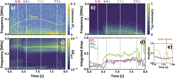
Figure 10. A measured edge fluctuations during ELM-suppression state. (a) Coherence of edge Te fluctuation from electron cyclotron emission imaging system. (b) Coherence of edge ne fluctuation from beam emission imaging system. (c) Measured δBpol fluctuation at inner wall from MC. (d) Time trace of normalized integrated coherence amplitude of Te (red), ne (blue), and Bpol (green) fluctuations over the frequency space. (e) Zoom-in of (d) for 7.7–7.8 s. The normalized RMP coil current IRMP is illustrated in (a).
Download figure:
Standard image High-resolution imageLinear gyrokinetic simulations confirms that enhanced edge turbulence may occur in the ELM suppression phase. The gyrokinetic code, CGYRO [63], is used in the linear analysis of micro-instabilities. The linear initial value solver is employed to find the unstable mode in the target radial point with wavelength ky ρs = 0.1–1.5. This simulation is based on a flux-tube approach with a full gyro-kinetic description for both electron and ion channels. The reconstructed radial profiles and kinetic equilibrium described above are included for the accurate modeling. This calculation is performed at ψN = 0.96, where the changes of experimental fluctuations are robust. The linear growth rate and real frequency are normalized by E × B shearing rate (γE) and Bohm sound speed (CS).
As shown in figure 11(a), the normalized linear growth rates (γ) of turbulence mode exceed the onset limit (>1) after the transitions to the ELM-free state. This is mainly due to decreased stabilizing effect from the E × B shearing rate (γE) [45, 64], which comes from the degraded pressure pedestal (figure 5(b)) after entering ELM suppression (6.6 s). The real frequency and numerical testing indicates that the excited mode is an ITG/TEM hybrid mode, which mainly lies on ion direction as shown in figure 11(b). Here, the bi-normal wave length ky ρs ∼ 0.3 and real frequency ∼51 kHz of the most unstable mode exhibits similar properties to the measured fluctuations of electron channels. The simulation results show that ion thermal diffusion can be increased with these unstable modes, supporting the idea of ion temperature pedestal broadening by turbulence. However, theoretical analysis on RMP-induced turbulence still has many missing pieces. Recent studies have shown that the characteristics of transport in the presence of RMP deviates significantly from linear gyrokinetic calculations, raising the importance of non-linearity [65] and non-locality [66] which is not included in this linear analysis. In addition, the reduced gradient of ion temperature pedestal during its broadening can be explained by introducing RMP-induced transport. However, it is still less clear how it can contribute to increased width. In the future, nonlinear gyrokinetic studies including these aspects will shed further light on the accurate description of edge turbulence under RMPs.

Figure 11. The (a) normalized growth rates (b) and real frequency of instability calculated from CGYRO for four different time slices including 5.3, 6.3, 6.6, and 7.7 s.
Download figure:
Standard image High-resolution imageThe considerable effect of RMP-induced transport on ion heat diffusion might be inconsistent with the general trend of other devices [16, 17, 32], where such turbulence mainly affects electron channel and has a minor effect on ion transport. Although it is difficult to evaluate the turbulence effect on ne and Te due to limitations in the diagnostics, we still confirm that there is a clear correlation between edge fluctuation and ion temperature pedestal. Therefore, this observation suggests new possible role of turbulence in the ion temperature pedestal, where ELM-free state is achieved with the low-n (=1) RMP.
As discussed earlier, ion temperature pedestal widening is key to the fast and successful convergence of adaptive control. Because edge-turbulence can play important role on the ion-pedestal, the turbulence level should be well sustained to maintain such an favorable effect. However, figure 10(d) shows that the amplitude of edge fluctuation disappears as ELMs re-occur, and the favorable effects from widened ion temperature pedestal will also start to decrease. Here, the ion temperature pedestal will return to its initial ELMy state on an energy confinement time scale, so the advantageous turbulence effect can last a few 100 ms after returning to the ELMy phase. Thus, IRMP must re-increase immediately after the loss of ELM suppression fully exploit this effect. In this respect, a real-time adaptive ELM control is a unique methodology both to utilize and control the edge turbulence and to uncover the novel beneficial effect of turbulence.
5. Conclusion
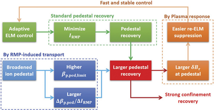
We have achieved successful optimization of a controlled ELM-free state with highly recovered confinement by  , maintaining βN ∼ 1.91, βp ∼ 1.53, and H98 ∼ 0.9, with the original degradation in fusion gain largely recovered. This novel adaptive approach exhibits compatibility between RMP ELM suppression and high confinement. In addition, it provides a reliable strategy to achieve stable ELM-free access by preventing RMP-induced disruption. It is noteworthy that the remarkable recovery of confinement is not solely attributable to adaptive RMP control but also to a widened ion temperature pedestal resulting from RMP-induced transport that promotes pedestal recovery by improving the ion response and ELM stability and facilitates fast, stable, and reinforced control optimization (figure 12). This feature, which can be correlated to the turbulent process, is a good example of a system that transitions to an optimal state through a self-organized response to adaptive modulation. These results with low n = 1 RMP confirm that adaptive ELM control is a highly promising approach toward optimizing the ELM-free state, potentially solving one of the most challenging obstacles for viable and economical fusion energy.
Figure 12. Schematic diagram of correlation between adaptive ELM control and pedestal recovery. Here, it is noteworthy that the strong recovery of confinement is also attributable to the widened ion temperature pedestal by RMP-induced transport during ELM suppression phase.
Download figure:
Standard image High-resolution image
However, there are remaining features to be improved for a 'complete' adaptive ELM control picture. As shown in figure 1(a), the current approach is based on ELM detection and thereby inevitably faces several ELMs during control. This limitation could be critical at the reactor level, where a single ELM can already be dangerous. Thus, a way to detect the loss of ELM suppression in advance of the ELM re-occurrence is needed. Here, the behavior of edge turbulence suggests a potential solution. The amplitude of magnetic fluctuation during the ELM-free phase shows a rapid decrease 50 ms before the return of ELMs at 7.77 s (figure 10(e)). Such an abrupt change in magnetic signals is an effective indicator of suppression loss and has been also observed in other device [25]. Therefore, this property could be potentially utilized in real-time to entirely avoid the return of ELM to achieve truly ELM-free optimization. Future work will focus on developing its detection schemes.
Previous work has shown that the effectiveness of RMP ELM suppression can be enhanced by physics model-based 3D geometric optimization [67]. Since this adaptive ELM control scheme maximizes the plasma performance for a given scenario, any additional improvements from external forces will be augmented by the adaptive scheme. This makes the adaptive approach a prime candidate to fully exploit existing physics models for RMP ELM suppression.
Lastly, the demonstration of adaptive control in this work is limited to 11 s. Although the control convergence is likely to be achieved before 10.5 s, it is still important to check its validity and reproducibility in a longer pulse for its application in ITER. In addition, RMPs up to n = 5 will be utilized in ITER operation, so adaptive ELM control using higher n ( ) RMP also needs to be verified. Future investigation of these features will lead to broader operational freedom and higher confinement recovery, as well as the development of advanced ELM control techniques for ITER and future tokamaks.
Acknowledgments
The authors would like to thank the KSTAR team. This material was supported by the US Department of Energy, under Awards DE-SC0020372. This research was also supported by R&D Program of 'KSTAR Experimental Collaboration and Fusion Plasma Research (EN2021-12)' through the Korea Institute of Fusion Energy (KFE) funded by the Government funds. Computing resources were provided on the KFE computer, KAIROS, funded by the Ministry of Science and ICT of the Republic of Korea (KFE-EN2241-8).