


Abstract
Concepts of the power exhaust and divertor design have been developed, with a high priority in the pre-conceptual design phase of the Japan–Europe broader approach DEMO design activity (BA DDA). Common critical issues are the large power exhaust and its fraction in the main plasma and divertor by the radiative cooling (Pradtot/Pheat ⩾ 0.8). Different exhaust concepts in the main plasma and divertor have been developed for Japanese (JA) and European (EU) DEMOs. JA proposed a conventional closed divertor geometry to challenge large Psep/Rp handling of 30–35 MW m−1 in order to maintain the radiation fraction in the main plasma at the ITER-level (fradmain = Pradmain/Pheat ∼ 0.4) and higher plasma performance. EU challenged both increasing fradmain to ∼0.65 and handling the ITER-level Psep/Rp in the open divertor geometry. Power exhaust simulations have been performed by SONIC (JA) and SOLPS5.1 (EU) with corresponding Psep = 250–300 MW and 150–200 MW, respectively. Both results showed that large divertor radiation fraction (Praddiv/Psep ⩾ 0.8) was required to reduce both peak qtarget (⩽10 MW m−2) and Te,idiv. In addition, the JA divertor performance with EU-reference Psep of 150 MW showed benefit of the closed geometry to reduce the peak qtarget and Te,idiv near the separatrix, and to produce the partial detachment. Integrated designs of the water cooled divertor target, cassette and coolant pipe routing have been developed in both EU and JA, based on the tungsten (W) monoblock concept with Cu-alloy pipe. For year-long operation, DEMO-specific risks such as radiation embrittlement of Cu-interlayers and Cu-alloy cooling pipe were recognized, and both foresee higher water temperature (130 °C–200 °C) compared to that for ITER. At the same time, several improved technologies of high heat flux components have been developed in EU, and different heat sink design, i.e. Cu-alloy cooling pipes for targets and RAFM steel ones for the baffle, dome and cassette, was proposed in JA. The two approaches provide important case-studies of the DEMO divertor, and will significantly contribute to both DEMO designs.
Export citation and abstract BibTeX RIS

Original content from this work may be used under the terms of the Creative Commons Attribution 4.0 licence. Any further distribution of this work must maintain attribution to the author(s) and the title of the work, journal citation and DOI.
1. Introduction
Concepts of the DEMO reactor design feasible in physics and engineering aspects have been developed in the pre-conceptual design phase of Japanese and European DEMO fusion reactors. Japanese DEMO concept (JA DEMO 2014) [1, 2] aims for the steady-state operation, where the fusion power (Pfusion) was decreased from 3 GW in SlimCS [3, 4] to 1.5 GW level in order to find an appropriate divertor design, and the major radius (Rp) was increased from 5.5 m to 8.5 m in order to allow for enough space for the central solenoid coils for fully inductive plasma starting. The fast track European DEMO (EU DEMO1) aims for repeating two hours operation and producing net electricity (Pel.net) of 500 MW with Pfusion = 2 GW level and Rp = 9.1 m [5–7], based on the plasma performance of ITER with conservative improvements in physics and technology, compared to advanced DEMO2 with optimistic physics assumptions.
The collaborative DEMO design activities (DDA) has been conducted by Japan (JA) and Europe (EU) in the broader approach framework from 2010. The DDA is a collaboration activity that is supported by domestic DEMO design teams. In JA, the Joint Special Design Team for Fusion DEMO organizes to conduct the DEMO development programme in a nation-wide manner with an enlarged participation of industry. In EU, DEMO design and associated R&D are implemented by the power plant physics and technology under the EUROfusion consortium. The final report of BA DDA phase-I was published in February 2020 [8], which summarized achievements of nine common research topics. In the final report, the design integration and impacts on DEMO system design were emphasized.
Handling of the large thermal power from the confined fusion plasma is one of the most important issues for DEMO design. Concepts for the power exhaust and divertor design, consistent with their plasma scenarios, i.e. steady-state and pulsed operations, have been developed. Significant progress in the power exhaust concepts and DEMO relevant divertor designs has been made through the DDA work. Different power exhaust scenarios have been developed for EU and JA DEMO concepts, while a common critical issue is large total power exhaust in the main plasma and divertor by the radiative cooling (Prad tot), and large fraction in the total heating power (frad tot = Prad tot/Pheat ⩾ 0.8) is required compared to that for ITER (0.6–0.7). At the same time, both divertor designs were required to adequately handle the peak heat loads on the target (qtarget) of 10 MW m−2 level under neutron irradiation condition. The studies and design work were reported at the intermediate stage [9], and significant progresses were made recently both in simulation study and engineering design. These JA and EU design approaches will provide important case-studies for the future design improvement. This design study was provided for the steady-state power exhaust scenarios. Development of the plasma design and relevant equipment for suppressing or mitigating the edge localized mode activity will be necessary to finalize the DEMO plasma design in future.
Progress of the power exhaust scenario in JA and EU DEMOs is introduced in section 2. Progress and comparison of the divertor simulation studies for the power exhaust are shown in section 3. Recent progress and parameters of their diverter designs are summarized in section 4. Finally, common views of the divertor design from the physics and engineering studies are summarized in section 5.
2. Plasma design for power exhaust scenarios
The radiative cooling scenario with impurity seeding is a primary approach for the DEMO power exhaust. Higher-Z impurities such as argon (Ar), krypton (Kr) and xenon (Xe) are preferable for DEMO [4, 5] in order to increase radiation loss in the main plasma (Prad main) and to reduce the exhaust power to SOL (Psep) because of large radiation loss rate coefficient in the high Te (>100 eV) as shown in figure 2 of reference [4]. In JA DEMO, Ar seeding was used as a reference case, because relatively large radiation loss is expected also at lower Te ⩽ 50 eV in the divertor. Influence of the Ar seeding on the plasma performance was evaluated by JA system code (TPC [10]) as a function of the impurity concentration in the main plasma (cAr main = nAr/ne), as shown in figure 2 of reference [11]. For the case of JA DEMO 2014, Pfusion ∼ 1.5 GW was obtained for ITER-level cAr main of 2.5 × 10⁻³, where Psep was 294 MW and power handling parameter of Psep/Rp = 34.5 MW m−1 was required for the divertor design. Pfusion was reduced to less than 1.5 GW with further increasing cAr main due to dilution of the fuel ions, and at the same time, higher plasma performance such as H-factor (HH98y2 ⩾ 1.3) was required to maintain normalized β (βN = 3.4) and to obtain the bootstrap current ratio (fBS) of ∼0.6.
High plasma density was preferable for the plasma design, such as increasing Pfusion, reducing fuel dilution by impurities, producing a radiative edge, and power handling in the divertor. Greenwald density (nGW = Ip/πap 2 [1020 m−3, MA, m], where Ip and ap are plasma current and minor radius, respectively) was increased from 6.8 × 10¹⁹ to 7.5 × 10¹⁹ m−3 by increasing Ip from 12.3 to 13.5 MA, which was achieved by increasing the plasma elongation (κ95) from 1.65 to 1.75 in the same device size of Rp and ap [11]. Key parameters of the main plasmas and power exhaust of the 'JA DEMO higher-κ' proposal are summarized in the first column of table 1. The higher-κ proposal was based on improvement of the conducting shell design, i.e. increasing the electrical conductance (shell width) and installation also behind the inboard breeding blanket modules [12]. Increasing Ip also improved the plasma performance such as Pfusion and τE, thus reduction of Psep to 258 MW with comparable plasma performance (HH98y2 ∼ 1.3, βN ∼ 3.4) was obtained at higher cAr main ∼ 6 × 10⁻³, as shown in figure 1. Here, Psep above the L–H transition threshold power (Pth LH = 115 MW [13]) has enough margin (fth LH = Pth LH/Psep = 2.2), and frad main = 0.41 is slightly larger than that in ITER. Large Psep/Rp of 30.4 MW m−1 is still required for the power exhaust in the divertor.
Table 1. Key parameters of the main plasma and power exhaust.
| Parameters | JA DEMO higher-κ [11] | EU DEMO1 [6, 7] | ITER (Q = 10 inductive) |
|---|---|---|---|
| Operation | Steady-state | Pulsed 2 h | Pulsed 400 s |
| Rp (m)/ap (m) | 8.5/2.42 | 9.0/2.9 | 6.2/2.0 |
| A | 3.5 | 3.1 | 3.1 |
| κ95 | 1.75 | 1.6 | 1.70 |
| q95 | 4.1 | 3.5 | 3 |
| Ip (MA) | 13.5 | 18.0 | 14 |
| BT (T)/BT max (T) | 5.94/12.1 | 5.9/12.5 | 5.3/12 |
| Pfusion (MW) | 1694 | 2000 | 500 |
| Pel.net (MWe) | ∼300 | 500 | — |
| Paux (MW) | 95.6 | 50 | 73 (installed) |
| Q | 17.7 | 41 | 10 |
| Pα + Paux (=Pheat, MW) | 435 | 457 | 173 |
| HH98y2 | 1.3 | 1.1 | 1.0 |
| βN | 3.4 | 2.6 | 1.8 |
| fBS | 0.61 | 0.35 | 0.15 |
| Line-ave. ne (1019 m−3) | 8.7 | 8.7 | 10 |
| fGW (=ne/nGW) | 1.2 | 1.2 | 0.83 |
| cimp main (=nimp/ne) (%) | 0.6 (Ar) | 0.039 (Xe) + Ar | N2, Ne, Ar, ... |
| Prad main (MW) | 177 | 306 | ∼50 |
| frad main (=Prad main/Pheat) | 0.41 | 0.67 | ∼0.33 |
| Psep (MW) | 258 | 154 | ∼100 |
| Psep/Rp (MW m−1) | 30 | 17 | ∼16 |
| Pth LH (MW) in ne, DT | 115 | 133 | ∼84 |
| fth LH (=Psep/Pth LH) | 2.2 | 1.2 | ∼1.2 |
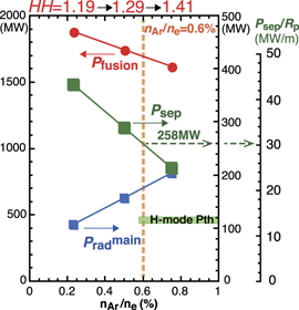
Figure 1. Fusion power (Pfusion), radiation power in the main plasma (Prad main), exhaust power to SOL (Psep) as a function of Ar impurity concentration (cAr main), for JA DEMO higher-κ design (κ95 = 1.75). Reproduced courtesy of IAEA. Figure from [11]. Copyright (2017) IAEA.
Download figure:
Standard image High-resolution imageFor the case of EU DEMO1, impurity seeding scenario with higher-Z impurities such as Kr and Xe, in addition to Ar, was proposed in order to increase Prad main and to satisfy the high priority requirement of reducing Psep/Rp to the ITER level [5–7]. Key parameters of the main plasmas and power exhaust of EU DEMO1 are summarized in the second column of table 1. EU system code (PROCESS [14]) studied variations of fth LH and DEMO size (Rp) for some cases of Psep/Rp with the plant design producing Pel.net = 500 MW and 2 h operation, as shown in figure 2 [6]: a reduction in BT and a large increase in Rp were necessary to increase fth LH for the fixed Psep/Rp case due to fth LH ∝ BT −1.5 Rp −0.1. Consequently, fth LH ∼ 1.2 uniquely corresponded to the power exhaust concept of Psep/Rp = 17 MW m−1 and Rp ∼ 9 m. It was noted that the ambiguity of Pth LH was relatively small from the L–H transition threshold database in low Zeff of less than 2 [15, 16], which was applied to the ITER operation. Further database with regard to impurity seeding and Pth LH scaling for higher Zeff are necessary to determine Pth LH for the DEMO plasma design.
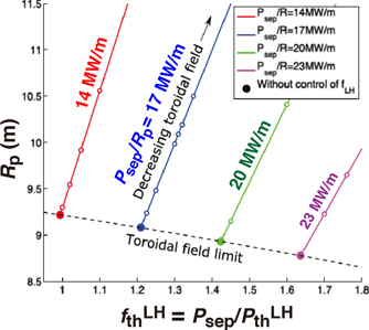
Figure 2. Dependence of the major radius on fLH for four cases of Psep/R = 14, 17, 20 and 23 MW m−1 in EU DEMO1. Net Pel.net = 500 MW and pulse duration of 2 h, while the major radius is minimized. Reproduced courtesy of IAEA. Figure from [6]. © 2017 EURATOM.
Download figure:
Standard image High-resolution imageCommon issues for the power exhaust remain in both JA and EU DEMOs. While the density fraction (fGW = ne/nGW) is increased to 1.2 and the line-averaged ne ( ) is comparable (8.7 × 10¹⁹ m−3) for both designs,
  is still lower than that for ITER. A relatively peaked profile of ne and a pedestal density of less than nGW will be necessary to obtain the high fGW plasma design. Experiments in JET-ILW and AUG reported the high fGW restriction (0.9–1) to obtain H-mode plasmas, where they used external gas puff fuelling [17]. Since the H-mode operation with high fGW > 1 is expected by pellet injection, it is also an important common issue for the DEMO design. Exhaust scenario of the large Pheat (435 MW and 450 MW for JA and EU DEMOs, respectively) is common high priority issue. Power exhaust concepts of the JA and EU DEMO designs are summarized in figure 3. Here, recent EU DEMO proposal (Flexi-DEMO [18]) foreseeing the steady-state operation in the same device (Rp = 8.4 m/ap = 2.71 m) for the pulse plasma operation is also shown; frad
main ∼ 0.62 and Psep/Rp ∼ 23 MW m−1 for the steady-state operationfor the steady-state operation, and frad
main ∼ 0.67 and Psep/Rp ∼ 20 MW m−1 for the pulse one. JA DEMO 2014 and higher-κ concepts challenge plasma performance higher than ITER-level with comparable frad
main (0.2–0.4), and divertor design appropriate for the larger Psep/Rp (30–35 MW m−1). On the other hand, EU DEMO concepts challenge increasing frad
main to 0.6–0.7 while keeping ITER-level HH98(y,2) (1.1 for pulse operations) and stable βN (2.6) by higher Z (Kr or Xe) impurity seeding in addition to Ar, in order to employ ITER-level power handling in the divertor (Psep/Rp = 17–20 MW m−1). At the same time, reduction of the divertor coverage, i.e. removing the divertor baffle, to increase the tritium breeding blanket volume is another challenge. Such high frad
main was reported in the ASDEX-Upgrade (AUG) H-mode experiment with Ar and nitrogen seeding [19, 20], and some database are also plotted. The long-pulse (20–30 s) H-mode plasma database with Ar seeding in JT-60U [21] are added.
is still lower than that for ITER. A relatively peaked profile of ne and a pedestal density of less than nGW will be necessary to obtain the high fGW plasma design. Experiments in JET-ILW and AUG reported the high fGW restriction (0.9–1) to obtain H-mode plasmas, where they used external gas puff fuelling [17]. Since the H-mode operation with high fGW > 1 is expected by pellet injection, it is also an important common issue for the DEMO design. Exhaust scenario of the large Pheat (435 MW and 450 MW for JA and EU DEMOs, respectively) is common high priority issue. Power exhaust concepts of the JA and EU DEMO designs are summarized in figure 3. Here, recent EU DEMO proposal (Flexi-DEMO [18]) foreseeing the steady-state operation in the same device (Rp = 8.4 m/ap = 2.71 m) for the pulse plasma operation is also shown; frad
main ∼ 0.62 and Psep/Rp ∼ 23 MW m−1 for the steady-state operationfor the steady-state operation, and frad
main ∼ 0.67 and Psep/Rp ∼ 20 MW m−1 for the pulse one. JA DEMO 2014 and higher-κ concepts challenge plasma performance higher than ITER-level with comparable frad
main (0.2–0.4), and divertor design appropriate for the larger Psep/Rp (30–35 MW m−1). On the other hand, EU DEMO concepts challenge increasing frad
main to 0.6–0.7 while keeping ITER-level HH98(y,2) (1.1 for pulse operations) and stable βN (2.6) by higher Z (Kr or Xe) impurity seeding in addition to Ar, in order to employ ITER-level power handling in the divertor (Psep/Rp = 17–20 MW m−1). At the same time, reduction of the divertor coverage, i.e. removing the divertor baffle, to increase the tritium breeding blanket volume is another challenge. Such high frad
main was reported in the ASDEX-Upgrade (AUG) H-mode experiment with Ar and nitrogen seeding [19, 20], and some database are also plotted. The long-pulse (20–30 s) H-mode plasma database with Ar seeding in JT-60U [21] are added.
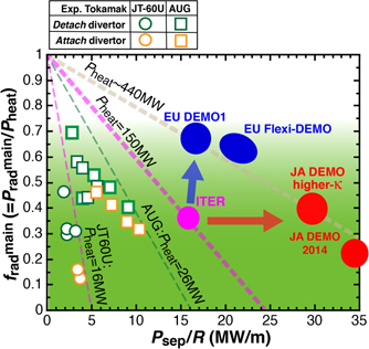
Figure 3. Fraction of Prad main in the total heating power (Pheat) and the divertor power handling (Psep/Rp) for ITER, EU and JA DEMOs. Impurity seeding experiments in AUG [20] and JT-60U [21] are also shown by squares and circles: orange and green colors correspond to attached and detached divertor cases.
Download figure:
Standard image High-resolution image3. Divertor design study for power exhaust scenario
A simple formula of the plasma heat load (qt plasma) is described by Psep, radiation fraction in the SOL and divertor (f* rad div = (Prad sol + Prad div)/Psep), characteristic length of the heat flux profile in SOL (λq SOL) and geometry parameters at the strike point, i.e. the poloidal angle between the separatrix and target surface (θdiv) and the magnetic flux expansion (fexp div = (Bp/Bt)mid/(Bp/Bt)div), as following, qt plasma = (Psep/Rp)·(1 − f* rad div)·(sin θdiv/fexp div)·(4πλq SOL Sdet div)−1, where power reduction by the plasma detachment is represented by an additional factor (Sdet div). Larger f* rad div compared to that of ITER (0.5–0.6) [22] is required, in particular, for the large Psep/Rp design. At the same time, restriction of ne at the main plasma separatrix (ne sep) is a common issue for the power exhaust for DEMO divertor. Medium values of the normalized density (ne sep/nGW) in the H-mode plasma experiments [23, 24] and 'standard' ITER simulations [25] corresponded to ∼1/3, and recent tokamak experiments with all metal plasma facing components (PFCs) and the edge ballooning stability model reported that ne sep/nGW was restricted lower than critical values of 0.4–0.5 [26]. The operation range of ne sep/nGW is expected to be 0.3–0.5, thus both DEMO divertor operations are required in the lower SOL density such as ne sep = 2–3.5 × 10¹⁹ m−3, corresponding to ne sep/nGW 0.27–0.48 and 0.29–0.51 for JA and EU DEMOs, respectively. Formation of plasma detachment and operation window of the JA and EU DEMO divertors are summarized.
3.1. Divertor designs for large power exhaust
Conventional divertor designs have been developed for the JA and EU DEMO concepts, based on the ITER divertor. Large power handling of Psep/Rp = 30–35 MW m−1 is a significant challenge for the JA DEMO, and a long leg divertor (Ldiv = 1.6 m, i.e. 1.6 times longer than ITER) was proposed as shown in figure 4(a). The inner and outer divertors cover all divertor plasma volume, and compression of the neutral particles and efficient formation of the plasma detachment will be expected particularly near the strike-point. The poloidal angles at the inner and outer targets (θdiv) are 30° and 25°, respectively, and the magnetic flux expansion factor, i.e. fexp div/sinθdiv, is similar (∼12) at the both targets. Design concept of the ITER divertor is simplified for the EU DEMO divertor in order to increase the tritium breeding blanket volume. While the similar long leg divertor with similar θdiv at the outer strike point is planned, the baffles and dome are removed, and the targets cover near the strike-points as shown in figure 4(b), which is rather open geometry compared to closed one such as the ITER and JA DEMO divertors.
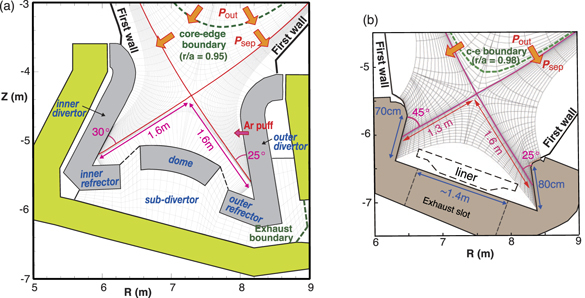
Figure 4. (a) SONIC simulation mesh and the divertor geometry of JA DEMO. Reproduced from [27]. CC BY-NC-ND 4.0. (b) SOLPS5.1 simulation mesh and the divertor geometry of EU DEMO.
Download figure:
Standard image High-resolution imageFigure 4 also shows calculation meshes of SONIC for the JA DEMO divertor and SOLPS5.1 for the EU DEMO divertor. Modelling of various drifts such as ∇B × B and E × B is not incorporated in the former code. The latter code does not activate the drift effects, and the liner is removed in this calculation. Exhaust power (Pout) and particle flux are given at the core-edge boundary. Pout = 250 and 300 MW are applied at the core-edge boundary (r/a = 0.95) for the JA DEMO higher-κ and JA DEMO 2014 reference cases, respectively. The total radiation power in the plasma edge (0.95 < r/a < 1), SOL and divertor (Prad edge + Prad sol + Prad div) was adjusted at a fixed value by feedback of the seeding rate in the iterative calculation, thus Psep is slightly smaller than Pout because of Psep = Pout − Prad edge. Reference of the radiation power fraction, i.e. (Prad edge + Prad sol + Prad div)/Pout, was determined to 0.8 for the two cases [11]. On the other hand, for the EU DEMO reference case, Pout = 150 MW is given at r/a = 0.98, thus Psep is comparable to Pout, and a series of the radiation power scan was performed with increasing the seeding rate. Application of diffusion coefficients on the ion and electron heat fluxes (χi, χe) and particle flux (D) for the SOL plasma is critical issue to simulate the divertor performance. For the JA DEMO, χi = χe = 1 m2 s−1 and D = 0.3 m2 s−1 were the same as the 'standard' values of ITER simulation by SOLPS4.3 [25]. The e-folding length near the outer midplane separatrix (λq// mid) of the parallel heat flux (q//) profile (including electron and ion components) corresponded to ∼3.0 mm, which was narrow compared to 3.6 mm in the ITER simulation due to higher Te mid and Ti mid in the JA DEMO (370 and 830 eV, respectively). For the EU DEMO, smaller χ = 0.3 m2 s−1 (inside separatrix) and 0.18 m2 s−1 (in SOL) were given to provide q// profile with comparable λq// mid of ∼3 mm.
3.2. Divertor operation in closed geometry (JA DEMO concept)
Divertor operation in low ne sep range and influences of the key parameters such as Psep, f* rad div and λq// mid were recently investigated in the JA DEMO with Ar seeding [27]. A series of ne sep scan was performed with changing fuel gas puff and divertor pumping rates, where Ar puff rate was controlled to keep a given value of Prad edge + Prad sol + Prad div. It is noted that Psep and f* rad div were slightly smaller than fixed parameters of Pout and (Prad edge + Prad sol + Prad div)/Pout, respectively. Two reference series for 'JA DEMO high-κ' (Psep ∼ 235 MW and f* rad div ∼ 0.78) and 'JA DEMO 2014' (higher Psep ∼ 283 MW and the same f* rad div), and extreme cases for the two references with reducing f* rad div to ∼0.7 were investigated. For the four cases, the total plasma power to the target, i.e. Psep·(1 − f* rad div), correspond to 50, 60, 75 and 90 MW, respectively. Distribution of the radiation loss in the inner and outer divertor by Ar seeding and profiles of plasma and heat load at the target were reported, for example, in figure 2 of reference [27]. The large radiation area was seen at the upstream of the inner target, and Te div was decreased to ∼1 eV over a wide area of the target, which we described as 'full-detachment'. In the outer divertor, large radiation peak was also seen at the upstream near the separatrix. On the other hand, it shifted towards the target at the outer flux surfaces. The plasma detachment was produced near the strike-point, which we described as 'partial detachment'. Typical plasma profiles and heat load components at ne sep = 2.0 × 10¹⁹ m−3 for the JA DEMO high-κ case are shown in figures 5(a) and (b). The width of the partial detachment for the reference case is relatively large (∼12 cm). Peak qtarget (∼5 MW m−2) appears at the boundary of the attached region, where Te div and Ti div are increased and ne div is decreased significantly, thus the peak qtarget is sensitive to their profiles. Profiles of Te div and Ti div at the attached region are relatively flat or rather increased towards the outer SOL, but they are still lower than those at the upstream SOL, as shown in figure 5(c), by radiative cooling. Total qtarget is evaluated by including surface recombination of the ions (qt rec = ni div Cs div Eion, where ni div, Cs div and Eion are ion density, sound velocity at the divertor sheath and recombination energy, respectively), radiation power load (qt rad) and neutral flux load (qt n), in addition to the plasma heat load (qt plasma). The peak qtarget is attributed by qt plasma and qt rad in the attached region. The width of the partial detachment corresponds to ∼1 cm of the midplane SOL radius, as shown in figures 5(c) and (d). Decay lengths of the parallel heat flux profiles near the separatrix at X-point (q//e Xp and q//e Xp + q//i Xp) are 2.3 and 2.9 mm (mapping to midplane radius), respectively. Extremely large heat flux in the near-SOL is significantly reduced in the divertor.
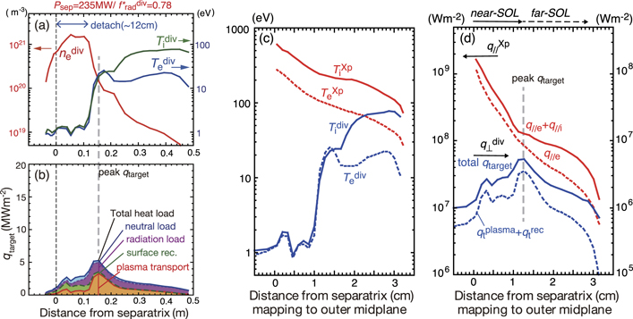
Figure 5. Profiles of (a) Te div, Ti div and ne div, reproduced from [27]. CC BY-NC-ND 4.0. (b) qtarget and integrating heat load components at the outer target for JA DEMO higher-κ with exhaust power of Psep ∼ 235 MW and radiation fraction of f* rad div ∼ 0.78. Profiles of (c) Te and Ti at the outer divertor and near the X-point, (d) electron and total parallel heat fluxes (q//e Xp, q//e Xp + q//e Xp), and the heat load at the outer target. Distances from the separatrix at the outer target and near X-point are mapped to the midplane SOL radius.
Download figure:
Standard image High-resolution imageSince the peak qtarget is generally larger than that of the inner qtarget, results of the outer qtarget are plotted in figure 6(c). Circles and squares show series of reference JA DEMO higher-κ and 2014 cases, respectively, where the peak qtarget in figure 5(b) is marked by open circle. The peak qtarget is gradually decreased in higher ne sep, compared to that in lower ne sep. The two series of f* rad div ∼ 0.8 are acceptable in expecting low ne sep (⩾2 × 10¹⁹ m−3) to reduce qtarget ⩽ 10 MW m−2. The JA-DEMO higher-κ case has advantages to provide enough operation margin to the recrystallization temperature of the tungsten target. Triangles and diamonds show series of lower f* rad div (∼0.7) cases. The peak qtarget is generally increased with increasing Psep·(1 − f* rad div), and it is increased with reducing width of the plasma detachment. Figures 6(a) and (b) show profiles of Te div, Ti div, ne div and heat load components at ne sep = 2.0 × 10¹⁹ m−3 for the JA DEMO higher-κ case with the lower f* rad div. The detachment width is decreased to 7 cm, which corresponds to inside of the near-SOL of the q// Xp profile. The peak qtarget is significantly increased to 12.5 MW m−2, where the local Te div increases to 32 eV, while the local ne div is similar at ∼2 × 10²⁰ m−3. In the outer flux surfaces (rdiv > 20 cm), ne div is decreased to a few 1019 m−3 and Te div and Ti div are increased. As a result, higher ne sep operations, i.e. ne sep ⩾ 2.3 × 10¹⁹ and 2.7 × 10¹⁹ m−3, are required for the two lower f* rad div cases.
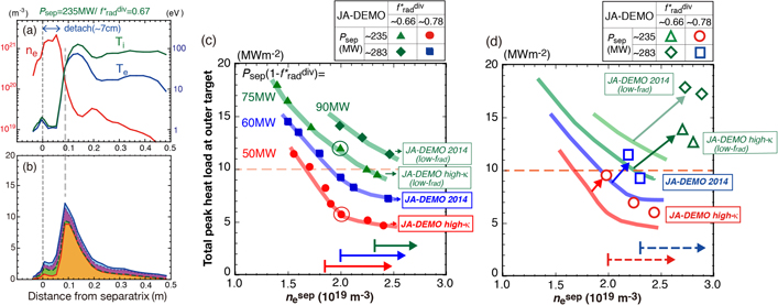
Figure 6. Profiles of (a) Te div, Ti divand ne div, (b) qtarget and integrating heat load components at the outer target for JA DEMO higher-κ with Psep ∼ 235 MW and f* rad div ∼ 0.66. Four series of peak qtarget for given Psep and f* rad div as a function of ne sep; Reproduced from [27]. CC BY-NC-ND 4.0. (c) different closed symbols (circle, square, triangle, diamond) and their guidelines show four cases with standard χ = 1 m2 s−1 and D = 0.3 m2 s−1, (d) open symbols show corresponding four results with reducing χ = 0.5 m2 s−1 and D = 0.15 m2 s−1 [27].
Download figure:
Standard image High-resolution imageAt the same time, while the peak qtarget is already reduced, low Te div and Ti div are required for the year-long divertor operation since the ion fluence is expected to be 50–100 times larger than ITER. Net erosion (Δd) was estimated at the peak qtarget in figure 5(a) (Te div ∼ Ti div ∼ 20 eV, ne div ∼ 1020 m−3) by a simple formula: Δd (mm) = 4.95 × 10⁻¹⁹ Rnet⋅Yi⋅Ci⋅Γi⋅t for W-surface, where Rnet, Yi, Ci, Γi and t are the ratio of net to gross erosion rates for the tungsten target, sputter yield, impurity concentration, incident ion flux and operation time (year), respectively. Rnet and Yi⋅Ci are critical factors and Yi is significantly increased under the attached plasma condition. Assuming Rnet = 0.1 and using Yi⋅Ci ∼ 4 × 10⁻⁴ for cAr div ∼ 0.2% [23] for the relatively low Te div ∼ 20 eV and Γi ∼ 1023 D m−2 s-1 for the reference JA DEMO higher-κ and 2014 cases, Δd is estimated to be 2.5 mm after a year-long operation, which is a half of the thickness of the monoblock design (5 mm). Simulation of the plasma material interaction including physics processes of Rnet will be necessary for further evaluation. Operation at further high ne sep or sweep of the strike-point location will be required.
Furthermore, effect of smaller λq// mid on the divertor operation of the JA DEMO divertor was investigated with reducing both χ and D to half values, i.e. χe = χi = 0.5 m2 s−1, D = 0.15 m2 s−1 [27]. The radial gradients of Te mid, Ti mid and ne mid were increased, and λq// mid of the q//e Xp + q//i Xp profile was decreased to 2.2–2.6 mm. Both peak qtarget and ne sep were increased for each case. Lower boundary of ne sep for qtarget ⩽ 10 MW m−2 was determined to be 2.0 × 10¹⁹ and 2.3 × 10¹⁹ m−3 for the JA DEMO higher-κ and 2014 reference cases, respectively, as shown in figure 6(d). The influence was enhanced with reducing f* rad div; both peak qtarget and ne sep were significantly increased for f* rad div ∼ 0.7. As a result, the divertor operation was difficult in the low ne sep range of 2–3 × 10¹⁹ m−3. Therefore, f* rad div ∼ 0.8 was determined as the reference value of the divertor performance for the JA DEMO 2014 and higher-κ cases.
3.3. Divertor operation in open geometry (EU DEMO concept)
The divertor plasma performance for the EU DEMO divertor has been investigated from Psep/Rp = 17 MW m−1 (reference) to 22 MW m−1, using SOLPS5.1. Here, ne sep = 2.9–3.3 × 10¹⁹ m−3 was higher than that of JA DEMO, but lower than that of ITER. Reductions in Te div and qtarget were investigated with increasing the Ar seeding rate in addition to small Kr or Xe seeding. Results are shown as a function of cAr SOL in figures 7(a) and (b), where qtarget includes qt plasma, qt rec and qt n, but not qt rad. These results are also plotted as a function of f* rad div in figure 7(e). For the reference case (Psep = 150 MW), appropriate power handling of the divertor (qtarget ⩽ 10 MW m−2) is achieved at f* rad div ⩾ 0.67 (cAr mid ⩾ 0.3%), which is slightly larger than ITER. At the same time, peak Te div is decreased as shown in figure 7(c); the partial detachment is not clearly produced, while the peak Te div at 2–6 cm away from the separatrix is decreased. Further requirement of low Te div (⩽5 eV) for reducing the target erosion to ignoring level is fulfilled at f* rad div ⩾ 0.78 (cAr mid ⩾ 0.45%). Appropriate divertor operation is restricted in the large f* rad div similar to that in the JA DEMO. Furthermore, the plasma detachment (Te div = 1–2 eV) will require to increase f* rad div > 0.85 (cAr mid > 0.5%). Wider cAr mid scan is performed for Psep = 200 MW. The peak qtarget is reduced to less than 10 MW m−2 with increasing f* rad div to 0.85 (cAr SOL ∼ 1.9%), while the peak Te div ∼ 40 eV in the outer region as shown in figure 7(d). Larger f* rad div ∼ 0.9 (cAr mid ∼ 2%) is required to achieve appropriate divertor operation with reducing Te div ⩽ 5 eV, and 'full detachment' is produced in f* rad div ∼ 0.93 (cAr mid ∼ 2.6%).

Figure 7. Three Psep series of (a) Te div, (b) peak qtarget at the outer target as a function of cAr SOL (nAr SOL/ne SOL). Profiles of Te div at outer target for (c) Psep = 150 MW and (d) Psep = 200 MW. (e) Te div and qtarget for EU DEMO divertor as a function of f* rad div.
Download figure:
Standard image High-resolution imageAs a result, the divertor power handling (qtarget ⩽ 10 MW m−2) was achieved for the three Psep cases in the open and shallow divertor geometry, where the partial detachment were not clearly formed. Further requirement of the low Te div (⩽5 eV) could be achieved at large f* rad div ∼ 0.8 and cAr mid ∼ 0.5% for the reference (ITER-level Psep/Rp) case. It would be possible to reduce the peak qtarget efficiently by improving the divertor geometry, but this is determined from physics and engineering requirements such as control of the large radiation in the long divertor leg and extending the tritium breeding blanket volume.
3.4. Detachment plasma formation in different divertor geometries
Plasma simulations of the JA DEMO divertor were performed also for lower Psep ∼ 150 MW (Pout = 160 MW) in order to compare detachment characteristics in the closed and open geometries with similar Psep. Profiles of Te div, Ti div, ne div and heat load components at the outer target for ne sep = 1.9 × 10¹⁹ m−3 and f* rad div ∼ 0.67 are shown in figures 8(a) and (b). Both Te div and Ti div are reduced to 1–2 eV near the separatrix (∼13 cm), and slightly wider 'partial detachment' is produced. In the attached plasma region, Te div and Ti div are increased similar to those for the larger Psep cases, and the peak qtarget appears in the attached plasma region (rdiv ∼ 16 cm), where the plasma transport component becomes dominant. Comparison of Te div in the JA and EU DEMO divertor simulations is summarized as a function of f* rad div in figure 8(c); the peak qtarget ⩽ 10 MW m−2 is achieved for all results in both DEMO divertors. While Te div (and qtarget) near the separatrix is significantly reduced in the JA DEMO divertor, Te div at the peak qtarget is still high 25–28 eV for f* rad div ∼ 0.6 and 18–20 eV for f* rad div ∼ 0.7. On the other hand, the EU DEMO divertor requires f* rad div ⩾ 0.67 to reduce qtarget ⩽ 10 MW m−2, and further high f* rad div ⩾ 0.78 to reduce near-separatrix Te div ⩽ 5 eV. This comparison shows benefit of the closed geometry in order to reduce qtarget, Te div and Ti div near the separatrix. At the same time, low Te div and Ti div is required to reduce the target erosion for the year-long operation as was discussed in section 3.2. For the low Psep case of the JA DEMO, ne div is reduced from ∼1 × 10²⁰ to 2–3 × 10¹⁹ m−3 and Te div ∼ Ti div ⩽ 20 eV at the peak qtarget. Although net erosion of the tungsten target will be smaller than the reference cases, further improvements of the divertor geometry and operation options such as different seeding impurity will be explored in order to extend the partial detachment width and to reduce local Te div and Ti div at the attached plasma region. At the same time, feasible values or profile of the diffusion coefficient over the near- and far-SOLs will be demanded in order to determine the divertor operation for the DEMO design.
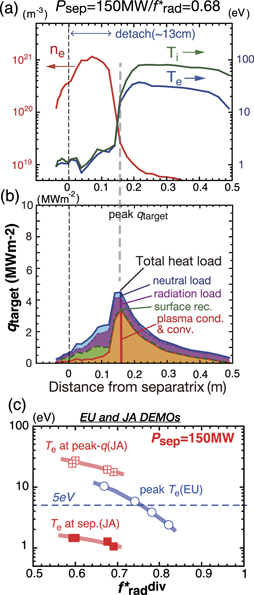
Figure 8. Profiles of (a) Te, Ti, ne, (b) qtarget and integrating heat load components in JA DEMO divertor with Psep = 148 MW and f* rad div ∼ 0.67. (c) Comparison between JA and EU simulation results for Psep ∼ 150 MW: Te div near the separatrix and Te div at the peak qtarget in JA DEMO divertor, and peak Te div in EU DEMO divertor.
Download figure:
Standard image High-resolution imageConsequently, owing to the different power exhaust concept of the main plasma, divertor performances with Psep/Rp = 17 and 30–35 MW m−1 for the EU and JA DEMOs, respectively, were numerically demonstrated. Some common views were achieved, (i) the peak qtarget can be reduced to less than 10 MW m−2 in the long leg divertor (Ldiv = 1.6 m) by increasing f* rad div larger than ITER-level (0.5–0.6), (ii) closed divertor geometry is efficient both to produce the plasma detachment and to reduce peak Te div and Ti div, and (iii) adequate reduction of Te div and Ti div is required by increasing f* rad div ⩾ 0.8. It was noted that net erosion rate under the partially detachment condition may become a critical lifetime issue of the DEMO divertor. Further optimization of the divertor geometry and operation parameters (f* rad div, ne sep, seeding impurity species, etc) as well as determination of the appropriate physics parameters such as diffusion coefficients are necessary in both divertors. At the same time, benchmark study between updated versions of both SONIC (JA) and SOLPS (EU) codes in the same geometry and input parameters is required to discuss physics models incorporated.
4. Engineering design and technology developments for the DEMO divertor
4.1. Design concepts and comparison of key parameters
Water-cooled divertor target design of the ITER technology, i.e. W-monoblock, Cu-alloy (CuCrZr) cooling pipe and Cu-interlayer, is a common baseline concept of JA and EU DEMO divertors. Recent status of the JA and EU divertor designs is summarized in table 2, which is updated from 2015–2016 designs [9], and details of each design concept are explained in section 4.2. Common design issues and requirements were identified during the BA DDA. Number of the divertor cassette (48) is now the same for both DEMOs, and three adjacent divertor cassettes are replaced through one maintenance port for the maintenance. Total weight of one JA divertor cassette (∼22 ton) is 2.7 times heavier than EU divertor cassette (8.3 ton) since the former covers most of the divertor plasma below the X-point, similar to the ITER divertor.
Table 2. Key parameters of armor, heat sink and cassette for the water-cooling divertor design of JA and EU. Upper target and baffle are removed in EU divertor.
| JA DEMO (2020) | EU DEMO (2019) | ||
|---|---|---|---|
| Number of cassettes for toroidal coverage | 48 | 48 | |
| Number of divertor maintenance ports | 16 | 16 | |
| Weight of one divertor cassette (ton) | ∼22 | 8.3 | |
| Target | Number at inner/outer units in a cassette | 32/43 | 31/43 |
| PFC/heat sink pipe | W/CuCrZr | W/CuCrZr | |
| Water temperature (°C)/pressure (MPa) | 200/5 | 130/5 | |
| Flow velocity at inner/outer (m s−1) | 11/11 | 16/16 | |
| CHF (MW m−2) | 28 | 48 (150 °C) | |
| Irradiation on PFC (dpa fpy−1) | <0.5 | <2.0 | |
| Irradiation on cooling pipe (dpa fpy−1) | <1.5 | <7.2 | |
| Upper target (baffle) | PFC/heat sink pipe | W/F82H | |
| Water temperature (°C)/pressure (MPa) | 290/15 | — | |
| Flow velocity at inner/outer (m s−1) | 2.8/2.3 | — | |
| Irradiation on PFC (dpa fpy−1) | <2 | — | |
| Irradiation on cooling pipe (dpa pfy−1) | <6 | — | |
| Dome (JA)/liner (EU) | PFC material (number in a cassette) | W-monoblock design (37) | W-(2 mm-thick) coating/plate |
| PFC/heat sink | W/F82H | W/Eurofer 97 | |
| Water temperature (°C)/pressure (MPa) | 290/15 | 180/3.5 | |
| Flow velocity (m s−1) | 3.6 (separate) | Variable (series to cassette) | |
| Irradiation on PFC (dpa pfy−1) | <1.6 | <1.8 | |
| Irradiation on heat sink (dpa pfy−1) | <5 | <4.9 | |
| Cassette | Structural material | F82H | EUROFER97 |
| Water temperature (°C)/pressure (MPa) | 290/15 | 180/3.5 | |
| Flow velocity at inner/outer (m s−1) | 1–2 | Variable | |
| Irradiation on cassette (dpa pfy−1) | <3 | <6 | |
Neutron irradiation on the W-monoblock and Cu-alloy heat sink is significantly increased in the both DEMOs due to increasing operation time as well as the neutron flux. The maximum irradiation doses for a full power year (fpy) become larger than those for the full operation period of the ITER divertor, which are 0.54 and 2.5 displacements per atom rate (dpa), respectively [28]. Therefore, the engineering design and technology of the divertor component should consider reductions of irradiation damage and degradation of material properties until the planned replacement. Reduction in the thermal conductivity of W will be acceptable up to several dpa (∼3 years), which is comparable to replacement of the tritium breading blankets. Selection of Cu-ally (CuCrZr or Cu-base composites) for the heat sink material is owing to the excellent thermal conductivity. Design constrains under the neutron irradiation condition are summarized in table 3. Design constrains of the power handling will be firstly determined by mechanical property of Cu-alloy at high temperature (>280 °C) due to radiation induced softening and creep [29, 30]. Corrosion on the inner wall of the pipe above 200 °C is another common design issue. At the same time, radiation induced hardening at the low temperature also starts from the low irradiation dose (∼0.2 dpa). Therefore, the coolant temperature (Tcool) for the high heat flux component is increased to higher than that of ITER (∼70 °C), and the selection of Tcool (JA: 200 °C, EU: 130 °C) would be a critical lifetime issue. Comprehensive database of these properties, design criteria and their improvement are required to determine the life time of the power handling unit.
Table 3. Design constrains of Cu and Cu-alloy under neutron irradiation condition.
| Softening | Embrittlement | Thermal cond. reduction | ||||
|---|---|---|---|---|---|---|
| Radiation-induced (dpa) | Embrittlement by transmuted He (dpa) | Reduction (20%) bytransmuted product(dpa) | ||||
| Heat sink/coolant pipe | Yield strength at RT (MPa) | Threshold (°C) | Hardening | Softening | ||
| Pure-Cu | ∼60 | — | ∼0.1 | — | 6 (at 350 °C) 40 | 10 |
| appm limit | ||||||
| with 7 appm dpa−1 | ||||||
| CuCrZr | >400 | 280 | ∼0.2 | ∼1 | 10 | |
| ODS-Cu (GlidCop [31]) | >400 | 300 | ∼0.2 | 1–2 | 10 | |
4.2. Heat removal unit, cooling water condition and cassette design
Arrangement of heat removal units and the coolant pipes in the divertor cassette for the JA DEMO, and cooling water temperature and flow velocity are shown in figures 9(a) and (b). Heat sink, i.e. CuCrZr or reduced activation ferritic martensitic (RAFM) steel (F82H) pipes, was determined based on neutronics calculation and simulation result of the heat load profile. CuCrZr heat sink units were incorporated to the inner and outer targets, which can broadly cover the high heat load region of 0.8 m near the strike-point. The neutronics calculation showed that the maximum dose was ∼1 and ∼1.5 dpa for the inner and outer targets, respectively, for year-long steady-state operation as shown in figure 8 of reference [11], thus the replacement will be expected every 1–2 years, i.e. more frequently compared to that of the blankets. Pressurized water with relatively high inlet Tcool of 200 °C (5 MPa) was used to minimize the irradiation embrittlement. Upper temperature limit for the CuCrZr pipe was provided to be 350 °C, whereas influence of thermal softening is somehow fostered above 280 °C–300 °C [32]. Tcool increases to 231 °C, and it is well below the critical heat flux (CHF) of 28 MW m−2. Arrangement of the cooling water route for inner and outer targets was recently revised from series to parallel to supply the coolant with comparable velocity of 11–12 m s−1 in order to reduce the pressure drop at the inner target with incorporating smaller number of the W-monoblock units, i.e. 32 and 43 for the inner and outer units. This is also common design in JA and EU DEMO divertors.
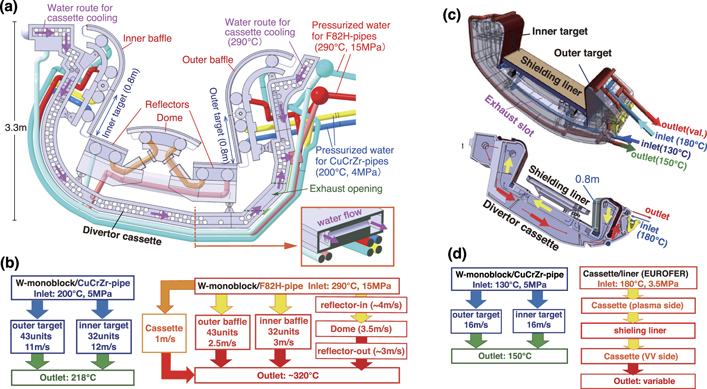
Figure 9. Design of JA DEMO divertor (2020): (a) arrangement of the targets, baffles, reflectors, dome and cooling pipes in a cassette, (b) flow velocity, coolant temperature and pressure in the CuCrZr and F82H pipes for the heat sink units. Here, heat removal is evaluated with assuming both the inner and outer qtarget to be 10 MW m−2, which was larger than the simulation result in section 3.2. Recent design of EU DEMO divertor (2019): (c) cassette with target plates, neutron shielding liner and cooling manifold, (d) flow velocity, coolant temperature, pressure for targets and cassette body.
Download figure:
Standard image High-resolution imageThe W-monoblock units with F82H pipe were arranged at higher neutron irradiation region such as baffles, dome and reflectors, where the dpa rate on the F82H pipe was increased up to 5–6, but qtarget was lower than a few MW m−2. High Tcool water (290 °C, 15 MPa) similar to the blankets [33] was used for the electricity generation by turbine system similar to a pressurized water fission reactor. In the heat exhaust evaluation of the cooling water routes as shown in figure 9(b), the total thermal power to the divertor was assumed to be 380 MW including 40%–70% margin, which was larger than the simulation result to the divertor chamber (∼270 and ∼220 MW for the JA DEMO 2014 and higher-κ cases, respectively). In addition, nuclear heating of the target units (totally 118 MW) was considered. Since maximum heat load to the divertor baffles, dome and reflectors was 1–1.5 MW m−2 in steady-state operation, the cooling water route to the reflectors and dome was arranged by a series connection due to benefit in remote maintenance, i.e. reducing cooling pipe branches and joints.
The water-cooled target concept is selected for the EU DEMO as a baseline concept [32, 34–36], which can take advantages of the thermal conductivity and the thermohydraulic properties compared to helium gas. The divertor configuration has been revised recently to the one shown in figures 9(c) and (d). Both the inner and outer baffles were removed, and the breeding blanket was extended instead, in order to increase the tritium breeding volume. At the same time, the total weight was reduced to ITER-level (8.3 tons). Length of the vertical target was comparable to the JA divertor target (0.8 m). The coolant route was divided to the inner and outer targets. The inlet temperature was recently reduced from 150 °C to 130 °C, and the flow velocity were increased to 16 m s−1 in order to increase the CHF to 48 MW m−2. On the other hand, because of removing divertor baffles, the maximum dpa rates on the W armor and CuCrZr pipe of the target were increased to 2.0 and 7.2 dpa fpy−1, respectively. Here, these dpa rates on the W armor and CuCrZr pipe are comparable to those on the divertor baffle for the JA DEMO divertor, where the dpa rate for CuCrZr is slightly larger than that for F82H ferritic steal. It is noted that the dose for the CuCrZr pipe at the outer strike point is expected to reach 2.8–3.7 dpa fpy−1 for the EU-DEMO divertor [37, 38], which is larger than ∼1.2 dpa fpy−1 for the JA DEMO [11], due to influence of the open and shallow divertor geometry. Reduction in the thermal conductivity of CuCrZr and Cu-interlayer is anticipated at larger than 10 dpa for multi-year operation. Degradation of the mechanical property of heat sink and joint/interlayer caused by radiation induced softening and/or hardening at the lower dpa can be minimized by application of new W and Cu/Cu-alloy target concepts as shown in section 4.4.
Cassette body design for the DEMO divertor has been developed both for EU and JA to incorporate the power exhaust units and coolant pipes, which will be consistent with reducing the fast neutron flux to protect the vacuum vesse (<2.75 dpa) and replacement of the power exhaust units. Number of the main coolant pipes is minimized to 4 for the both designs, and inlet and outlet are located at the outboard cassette. The cassette structures and cooling water condition are different, while the cassette structure can be made by welding of similar RAFM steel (Eurofer97 or F82H). EU cassette body is composed of a box structure with internal ribs, and it is cooled with another cooling loop with the inlet Tcool of 180 °C, which ensures the entire structure sufficient fracture toughness at the neutron damage (<6 dpa) [39, 40]. The dome ('liner') and reflectors are simplified from those in ITER as shown in figure 9(c). Since the exhaust slot is designed to be at the bottom of the cassette, the liner mainly has a role in reducing the neutron flux to the cassette and the bottom area of the vacuum vessel. The same coolant of the cassette body is used by a series connection as shown in figure 9(d). The interface between feeding pipes and fixation systems, and the design integration are on-going. JA cassette consists of thick (25 cm) plate structures with two lines of cylindrical coolant puddles in order to reduce the fast neutron and γ-ray fluxes. The exhaust slot is located at the outboard bottom in order to reduce the neutron flux to the vacuum vessel. The high Tcool water (290 °C, 15 MPa) is provided from the inboard and outboard manifolds of the cassette through the side routes of the cassette body to the puddles as shown in figure 9(b), and it finally exits to a manifold near the exhaust slot. The coolant velocity of 1.5 m s−1 is enough to remove the total nuclear heat of 0.7 MW in one cassette body, corresponding to totally 32 MW for 48 cassettes.
4.3. Heat and stress analysis of ITER-type monoblock design
Analysis of the heat transport and stress on the power exhaust unit of the JA DEMO target was carried out with three-dimensional modelling, considering the divertor heat load components in the partial detachment. The peak qtarget of 10 MW m−2-level on the flat target consists of combination of the plasma (along the magnetic field line) and radiation (perpendicular to the target) loadings. Figure 10(a) illustrates geometry of the fish scale W-monoblock target and heat flux components. The monoblock size in the toroidal direction, the gap width, the height between the adjacent surfaces, and the inner diameter of the coolant pipe were 25 mm, 0.5 mm, 0.4 mm, and 12 mm, respectively, which were similar dimension of the ITER monoblock target. Since the total incident angle of the magnetic field line to the fish scale target surface (2.4°) is smaller than ITER, the plasma-wetted area corresponds to 63% of the downstream side of the target. Two cases of the heat load profiles were given for heat transport analysis: the maximum W-surface temperatures correspond to ∼1200 °C (case-1), and ∼1400 °C (case-2), which appear near the downstream edge. The former and the latter correspond to just below and well above the critical temperature of W-recrystallization, and the peak qtarget at the plasma-wetted area are 13.5 and 15.2 MW m−2, respectively, as shown in figures 10(b) and (c). It is noted that these values correspond to the peak qtarget = 9.1 and 10.8 MW m−2 for the flat target. Nuclear heat in the W-monoblock is included, which is less than 10% of the total heat load. The maximum temperatures of the CuCrZr pipe, 351 °C and 365 °C, respectively, appear at the upper surface. Mechanical toughness of the cooling pipe is also near critical against thermal softening, thus, stress and elasto-plastic analysis were performed for the CuCrZr pipe as a structure material.
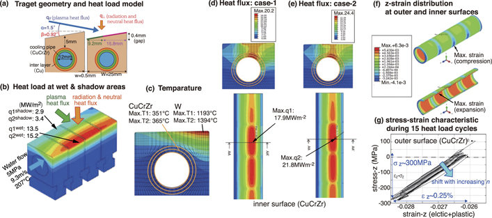
Figure 10. (a) W-monoblock geometry and the heat flux components to the fish scale target. Distributions of the surface temperature: (b) on four monobloaks near the peak heat load, (c) in the cross-section at the peak heat load. q1 and T1 correspond to the peak heat load and the peak temperature, respectively, for case-1. q2 and T2 are those for case-2. Distributions of heat flux at the inner CuCrZr pipe and cross-section at A–A: (d) case-1: lower and (e) case-2: higher heat flux cases. (f) Mechanical strain in z-direction at the outer and inner surfaces of the cooling pipe. (g) Stress–strain characteristic during 15 heat load cycles.
Download figure:
Standard image High-resolution imageThe heat fluxes up to 18 and 22 MW m−2 are widely distributed on the water side of the cooling pipe for case-1 and case-2, respectively, as shown in figures 10(d) and (e). These values are well below the CHF (28 MW m−2): the heat fluxes from the pipe to the coolant correspond to 64% and 79% of the CHF, which are acceptable for the heat removal. As a result, the target design with Tcool of 200 °C can handle the peak qtaret of 10 MW m−2 level including the nuclear heat, while less than 9 MW m−2 is preferable to minimize the surface recrystallization.
Residual stress and strain is also evaluated with repeating the high heat flux, where the surface temperature changes between base-temperature of 207 °C and peak value at each location as shown in figure 10(c). Here, zero strain is assumed at the brazing process (950 °C) as the initial condition of the analysis history. Result of elasto-plastic stress analysis in the extreme condition of the case-2 is summarized. Thermal stress of the W-monoblock is increased particularly at the upper and the side inner surfaces: Tresca-stress corresponded to 680 MPa. At the same time, some peaks appear at the upper inner surface and side outer surfaces of the CuCrZr pipe: Tresca-stress corresponds to 280 and 305 MPa, respectively. Figure 10(f) shows that elastic plus plastic strain, i.e. mechanical strain, in the pipe axis (z)-direction (εZ ) is increased at the inner (expansion) and outer (compression) of the CuCrZr pipe. The expansion is seen in the heat sink under the monoblock with increasing the heat flux. Thus, the compression of the heat sink is caused between the monoblocks. Stress (σZ )–strain(εZ ) trace at the maximum stress location shows similar trajectory during 15 heat load cycles in figure 10(g), but the maximum compression stress is gradually increasing. Change in εZ was ∼0.25%, which may not be critical for life time issue. Experimental study of fatigue will be required at the operation condition.
4.4. Development of target technologies for DEMO
Several technologies for the high heat flux target have been developed in EU [34] to survive under DEMO-relevant neutron irradiation condition. All are based on W as a baseline armour material, and Cu-alloy pipe with swirl tape to increase the heat transfer at the pipe wall. Material properties of CuCrZr and Cu-interlayer are anticipated to limit the performance of the target heat sink, e.g. irradiation creep above 350 °C and irradiation embrittlement below 250 °C [32]. Thus, it is reinforced by various kinds of Cu-W composite materials and novel interlayer materials as shown in figure 11 [41].
- (a)ITER-like W-monoblock with a CuCrZr cooling pipe is a baseline concept also in the DEMO divertor, but the monoblock size is modified to decrease the cross section width to 23 mm, instead of 28 mm in ITER, while the axis thickness of 12 mm is the same, in order to reduce thermal stresses. The armor thickness of 8 mm to the cooling pipe is comparable.
- (b)Thermal break concept (developed in CCFC) is based on ITER W-monoblock target. The concept features cut-outs in the Cu-interlayer in the area of the highest heat flux to achieve a more uniform distribution of the thermal flux around the cooling pipe circumference.
- (c)Composite pipe concept (developed in IPP) is based on a W wire-reinforced Cu composite pipe, which expects better strength of the cooling pipe, in particular, at high temperature (>350 °C).
- (d)Functionally graded W/Cu (FGM) interlayer concept (developed in CEA) aims replacing thick Cu interlayer, which is expected to be fully embrittled by fast neutron due to segregation of transmuted He at grain boundaries. Graded thin (30 μm) and think (500 μm) W–Cu interlayer is used to improve joining strength.
- (e)Flat-tile concept with a composite heat sink block (developed in IPP): W particle-reinforced Cu composite block is expected to enhance the mechanical resilience of the irradiated heat sink against structure failure. The use of the W–Cu composite is supposed to reduce the thermal expansion mismatch between the armor tile and the heat sink block.
- (f)In addition, He cooling target using multi-jet pipe by W and W-laminate (developed in KIT) is also developed as an option [36].

Figure 11. High heat flux target technologies developed in EU. Reprinted from [41], Copyright (2021), with permission from Elsevier.: (a) ITER-like monoblock baseline concept, (b) thermal break interlayer concept, (c) composite pipe of W-wire in Cu (Wf/Cu), (d) graded interlayer, (e) flat W-tiles and W particle/Cu composite block, (f) He cooling target using multi-jet pipe.
Download figure:
Standard image High-resolution image
Recently, small-scale mock-ups of each concept have been fabricated and tested by means of hydrogen neutral beam in the GLADIS under the high power density at 20 MW m−2 up to 500 cycles (130 °C coolant, which is expected operation temperature). A good production quality and reliable high-heat-flux fatigue performance was demonstrated. All mock-ups showed intact structural integrity and stable heat removal capacity over the entire loading cycles. Modest roughening of the W-armour surface and swelling of the blocks due to inelastic deformation was found. The metallographic examination revealed that the upper half of the armour blocks were completely recrystalized, but no discernable cracks were found in any of the tested armor (290 blocks). Furthermore, other ITER-like mock-ups were tested at 25 MW m−2 up to 500 pulses (20 °C coolant) for overload tests. Also under the increased power density, the mock-ups exhibited intact structural integrity and stable heat removal capacity, even though there was a single fine crack (6 mm in depth) initiated from the armor surface which underwent a pronounced inelastic deformation leading to overall severe roughening. The mock-ups even withstood the overload up to 32 MW m−2 (5 pulses) without any detrimental impact nor melting. The future R&D will be focused on an upscaling trial towards a medium-scale manufacturing (40 cm length) using the W wire-reinforced composite pipe.
5. Summary
Significant progress in the power exhaust concepts and DEMO relevant divertor designs has been made through the BA DDA phase-I period (2011–2020). Different power exhaust scenarios have been developed for JA and EU DEMO concepts, while a common critical issue is the large power exhaust of Pheat = 430–460 MW in the main plasma and divertor by the radiative cooling (Prad tot/Pheat ⩾ 0.8). The JA proposed a conventional closed divertor geometry to challenge large Psep/Rp handling (∼30 MW m−1) in order to maintain the radiation fraction of the main plasma at slightly larger than the ITER-level (frad main = Prad main/Pheat ∼ 0.4) and higher plasma performance (HH98y2 ∼ 1.3). The EU challenges both increasing frad main to ∼0.65 and handling the ITER-level Psep/Rp in the open divertor geometry, where increasing the tritium breading blanket volume is anticipated.
Power exhaust simulations have been performed by SONIC (JA) and SOLPS5.1 (EU) in similar long leg divertor (1.6 m) with similar q// profile width (λq// ∼ 3 mm), where Psep = 250–300 MW (JA) and 150–200 MW (EU). Large divertor radiation fraction (f* rad div = Prad div/Psep ⩾ 0.8) was required to reduce both peak qtarget (⩽10 MW m−2) and Te div in ne sep range (JA: 2–3 × 10¹⁹, EU: ∼3 × 10¹⁹ m−3) lower than ITER. In addition, the JA divertor performance was simulated with the EU-reference Psep of 150 MW. This comparison showed benefit of the closed geometry to reduce the peak qtarget and Te div near the separatrix, and to produce the partial detachment. At the same time, further improvements of the divertor geometry and operation options such as different seeding impurity will be explored in order to extend the partial detachment width and to reduce local Te div and Ti div at the attached plasma region. Feasible values or profile of the diffusion coefficient over the near- and far-SOLs will be also demanded in order to determine the divertor operation for the DEMO design.
Integrated designs of the water cooled divertor target, cassette and cooling pipe routing have been developed in both EU and JA, based on the tungsten (W) monoblock concept with Cu-alloy pipe. For year-long operation, DEMO-specific risks such as radiation embrittlement of Cu-interlayers and Cu-alloy cooling pipe were recognized by both JA and EU, and further restrictions of qtarget and Te div were anticipated. Both foresee higher water temperature (130 °C–200 °C) compared to that for ITER. At the same time, several improved technologies of high heat flux components have been developed in EU in order to reduce thermal stress and to strengthen the heat sink and interlayer. Different heat sink design, i.e. Cu-alloy cooling pipes for targets and RAFM steel ones for the baffle, dome and/cassette, with appropriate water conditions, i.e. 200 °C/5 MPa and 290 °C/15 MPa, respectively, was proposed in the JA divertor. The latter pressurized water will be used for the electricity generation. The two approaches provide important case-studies of the DEMO divertor, and will significantly contribute to both DEMO designs.
Acknowledgments
SONIC simulations were carried out within the framework of the Broader Approach DEMO Design Activity, using the JFRS-1 supercomputer system at CSC, IFERC, Rokkasho, Japan. Authors particularly thank continuous support by Japan and Europe home teams (QST in Rokkasho, and EUROfusion Programme Management Unit in Garching), and DDA unit of the IFERC project team.