


Abstract
The International Fusion Materials Irradiation Facility (IFMIF) is a projected accelerator-based, D-Li neutron source for fusion reactor materials qualification. LIPAc (Linear IFMIF Prototype Accelerator) is an accelerator aiming to generate a 125 mA, 9 MeV continuous wave deuteron beam, which is currently being commissioned in Rokkasho (Japan) with the objective of validating the IFMIF accelerator design.
In LIPAc, a 10 m long High Energy Beam Transport line (HEBT) will connect the exit of the superconducting linac to the beam dump (BD). The HEBT line must accommodate the diagnostics for beam characterization and open the beam at the end to allow its stopping at the BD. The line contains several magnets to control the beam shape and its trajectory, maintaining beam losses below 1 W m−1 along the beamline to limit activation of surrounding elements and allow hands-on maintenance.
In this work, the LIPAc HEBT line project is described since its origins. A summary of the beam dynamics calculations and other studies (vacuum, radioprotection, assembly, alignment) that led to the conceptual design of the line is done. After that, the detailed design of the line is presented, justifying the main design decisions taken and finally, the manufacturing and procurement process and the acceptance tests performed are summarized.
Export citation and abstract BibTeX RIS
1. Introduction
The International Fusion Materials Irradiation Facility (IFMIF) [1, 2] is a powerful neutron irradiation facility whose main goal will be to study properties of materials under severe irradiation in a neutron field similar to the one in a fusion reactor first wall. It is based on two accelerators producing a high current (125 mA) of 40 MeV deuterons which are focused on a fast flowing liquid lithium target to produce neutrons via D-Li stripping reactions. Presently a reduced version with one accelerator and consequently half of the neutron flux rate is being pursued in Europe. This installation, called IFMIF-DONES [3] will qualify the materials for the first fusion reactor to be connected to the electrical grid (DEMO). A similar installation has been also proposed in Japan [4].
LIPAc (Linear IFMIF Prototype Accelerator) is an accelerator aiming to reach 125 mA, 9 MeV continuous wave deuteron beam, which is currently being commissioned in Rokkasho, Japan. It is identical to the low energy part of the IFMIF accelerators and its final objective is the validation of the IFMIF accelerator design.
The LIPAc accelerator (see figure 1) includes an ion source (injector + Low Energy Beam Transport Line), a Radiofrequency Quadrupole cavity (RFQ), the first module of a superconducting linac (SRF linac) and a beam dump (BD) to stop the beam. It has also two transport lines: the Medium Energy Beam Transport line (MEBT), between the RFQ exit and the entrance to the SRF linac, and the 10 m long High Energy Beam Transport (HEBT) line, connecting the exit of the SRF linac to the entrance of the BD where the beam is stopped. This HEBT line is the object of this paper.
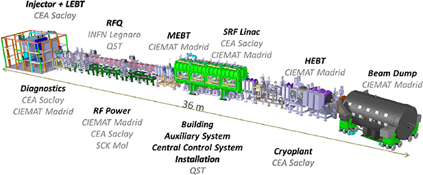
Figure 1. LIPAc, linear IFMIF prototype accelerator.
Download figure:
Standard image High-resolution imageThe high intensity of the LIPAc continuous beam, which has no precedent in any existing ion linear accelerator, poses specific problems for the design and manufacturing of the HEBT line. As it is intended to have hands-on maintenance, the particle losses must be limited to very low values (around a millionth of the beam per m). This represents a challenge, taking into account the presence of very strong space charge forces (reciprocal ion repulsion specially relevant at low energies). Another implication of the high current continuous beam is the neutron and gamma radiation environment under which the HEBT line must operate, generated as a consequence of the unavoidable beam losses and specially of the final stopping of the beam at the BD.
The HEBT line engineering design was completed in 2012 with the edition of the LIPAc HEBT and Beam Dump Engineering Design Report after a couple of reviews by external panel experts whose comments were incorporated. Subsequently, manufacturing specifications were written and the contracts of the different components were launched. All systems were shipped to the LIPAc site in Japan in 2018. The beam commissioning is expected to take place in 2020.
A number of challenges -mostly related to the high intensity and field effects- were taken into account from the first design stages and successfully solved. Other difficulties were found and fixed later during the manufacturing process. The experience gained during the design, manufacturing and tests may be useful in the design of high power ion accelerators. The aim of this paper is twofold: firstly, to describe the design of the HEBT line and secondly, to summarize the manufacturing activities and integration tests that were performed before the shipment of the HEBT components from Madrid, Spain to the LIPAc site at Rokkasho, Japan.
It is organized as follows: To begin with, a brief description of the HEBT line is presented (section 2). The main requirements of the LIPAc HEBT line are explained in section 3. Section 4 presents the beam dynamics studies performed for the transport line definition. Other studies needed for the line design concern vacuum, alignment, assembly, and radioprotection issues. These are presented in section 5. Section 6 describes the detailed design (which is based on the outcomes of the previous studies) and manufacturing of the HEBT line components. This work focuses specially on the description of the vacuum chambers that contain the beam along the HEBT line, the vacuum system and the supports. Some components belonging to the HEBT line such as the magnets [5], the diagnostics [6, 7], the lead shutter chamber [8] and the BD cartridge remote disconnection system [9], have been or will be described elsewhere. Therefore they are only briefly reported here for the sake of clarity and completeness. Finally, in section 7, the integration tests that were performed in Madrid to facilitate the subsequent installation works at the LIPAc site are described.
2. HEBT line overview
The design of the HEBT line was performed considering the geometry and power handling capacity of the BD, the space requirements for diagnostics and other elements, the total length restrictions, as well as the rest of requirements listed in section 3.4. As it will be explained in section 4, the HEBT line design is very compact along the beam direction, due to the high space charge of the beam.
Figure 2 shows a view of the 3D mock-up of the HEBT line and BD. As shown, the line contains a dipole that tilts the beam axis by 20º. The BD is located behind a 700 mm concrete wall in the so-called BD cell. The last elements of the line can not be seen in this figure as they are inside the BD shield.
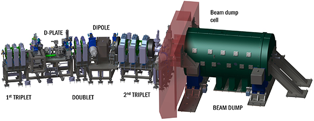
Figure 2. LIPAc high energy beam transport line and beam dump.
Download figure:
Standard image High-resolution imageThe main components of the HEBT line are indicated in figure 2 and described here. From left to right they are the following:
- A triplet of quadrupole magnets at the beginning of the transport line, to control the beam at the exit of the SRF linac, correcting possible errors and adjusting the beam parameters before the diagnostics plate.
- The diagnostics plate, which contains a full set of instruments to characterize the beam.
- A doublet of quadrupole magnets, to provide additional focusing, specially during the quadrupole scan emittance measurements which will be done changing the current of the first triplet quadrupoles [10].
- A bending magnet (dipole), whose main mission is to reduce the irradiation of the accelerator elements by the neutron and gamma radiation generated at the BD, by turning the beam 20º in the horizontal plane. Besides, it will allow beam energy spread measurements by means of interceptive slits installed before the dipole.
- A triplet of quadrupole magnets at the end of the HEBT line, to expand the beam and obtain a manageable power deposition density on the BD.
- A 2.6 m long drift from the exit of the quadrupole triplet up to the BD entrance, along which the beam is expanding, which traverses the BD cell wall and accommodates the last elements of the line.
The elements of the last drift are detailed in figure 3, which is a representation of the HEBT line in which the magnets have been hidden to show the beam chambers. The space between the second triplet of quadrupoles and the concrete wall contains many elements and among them the following:
- Beam profilers: Secondary Emission (SEM) grid for the commissioning at low duty cycle and ionization profile monitor (IPM) and fluorescence profile monitor (FPM) for continuous beam.
- A Lead shutter [8], to shield the gamma radiation which comes from the activated BD through the beam tube, allowing access to the accelerator vault when the beam is off.
- A scraper [8, 11], to reduce particle losses in the chambers inside the BD shield (where due to the high radiation levels no maintenance is possible) and protect them against off-normal too opened beams. It has an aperture radius of 57 mm and it is located in the same chamber as the lead shutter.
- Auxiliary shielding elements to attenuate the radiation coming from the BD during accelerator operation through the penetration in the BD cell wall. These are two polyethylene discs which have been located as close as possible to the beam axis, to collimate the neutron streaming [12].
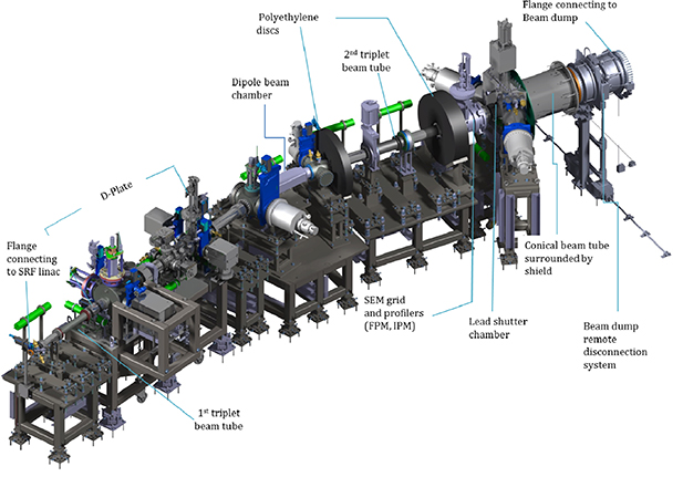
Figure 3. LIPAc high energy beam transport line (magnets not shown).
Download figure:
Standard image High-resolution imageBehind the wall, the line is connected through a set of bellows to the BD, with a special joint which allows the remote disconnection of the BD from the line [9].
Each group of quadrupoles contains two pairs of horizontal/vertical steerer magnets (also named correctors), which will be used to correct the beam trajectory (see section 4.3). Due to the compactness required in the beam direction, they share a common iron yoke with the quadrupole coils. The drifts after each quadrupole group include beam position monitors (BPMs) which provide the feedback signal needed for the correct beam alignment with the steerers.
3. Main function and requirements
3.1. Main function
The objective of the LIPAc HEBT line is to transport the beam coming out from the SRF linac up to the entrance of the BD, where its characteristics (size, divergence, shape) should be inside a specific range to ensure that the beam is safely stopped. Besides, the line must provide the space and conditions needed for a complete beam characterization.
In a first stage the HEBT and BD will be used for the commissioning of the accelerator up to the RFQ. In this stage, with 5 MeV deuteron beams, the space reserved for the SRF linac will be substituted by a transport line with quadrupoles [13]. In a second stage the whole accelerator will be operated pursuing the final aim of obtaining a 125 mA continuous current of 9 MeV deuterons. In both stages the commissioning will be done with pulsed beams with progressively increasing duty cycle. To minimize the accelerator activation, during the second stage it is planned to start the operation and make the first adjustments with H+ pulsed beams.
As the HEBT requirements needed to fulfill its function come mainly from the BD and the diagnostics needs, these two systems will be briefly described in the following subsections 3.2 and 3.3.
3.2. Beam dump
The LIPAc BD [11] is a copper cone (2.5 m long, 6.8° angle), cooled by water flowing at high velocity along its outer surface. The piece containing the copper cone and its cooling is named BD cartridge. This component is surrounded by a shield made of iron and polyethylene for attenuating the neutron and gamma radiation originated by the interaction of the deuterons with the BD material.
The mission of the last part of the HEBT line is to increase the size of the beam (which at the outlet of the linac has an rms radius of 4 mm), thus reducing its power density so that it can be safely stopped at the BD.
The BD was designed in parallel with the HEBT line. In fact, both designs are strongly interlinked, given that the distribution of deposited power in the cone is determined by the shape of the beam at its entrance which in turn is defined by the beam propagation through the HEBT line.
The thermal stresses at the BD surface are proportional to the temperature gradients which depend on the shape of the particle deposition along the BD surface. Thermomechanical studies show that a maximum power density of up to 300 W cm−2 at the BD surface can be managed correctly. In addition, to avoid thermal gradients in the copper cone in azimuthal direction, the beam must be as symmetric as possible, and coaxial with the BD. The mentioned thermomechanical studies included also a complete sensitivity analysis of its response to a change of the beam parameters [11]. From this analysis the following requirements for the beam at the BD entrance were obtained:
- Axi-symmetric beam with 40 mm rms radius in both transverse directions and 15–17 mrad divergence. ±10% variation allowed in these values
- Beam center deviations of less than 10 mm
3.3. Diagnostics
The HEBT line contains, as any transport line, beam instrumentation needed for its tuning and operation. LIPAc is a prototype accelerator whose main objective is to confirm the validity of its design and the matching of the characteristics of the resulting beam with those inferred from the simulations. Therefore the HEBT line contains also specific instrumentation for a thorough beam characterization. A full set of diagnostics are located in a 2.2 m long dedicated area called Diagnostics Plate or D-plate (represented in figures 2 and 3) and other diagnostics are distributed along the line.
The D-plate includes the following diagnostics (see figure 4):
- Three beam position monitors (BPMs)
- AC current transformer (ACCT)
- DC current transformer (DCCT)
- Fluorescence profile monitor (FPM)
- Ionization profile monitor (IPM)
- Residual Gas Bunch Length Monitor (RGBLM)
- Secondary Emission (SEM) grid with 100 × 100 mm of aperture
- A set of vertical and horizontal high power slits, 100 or 200 µm, for emittance measurements.
- Four Beam Loss Monitors based on ionization chambers (BLOM)

Figure 4. Diagnostics plate.
Download figure:
Standard image High-resolution imageAll these instruments are mounted on a common support frame. This allows positioning the D-plate after the RFQ and MEBT for the commissioning of the first part of the accelerator at very low duty cycle (before the installation of the HEBT line), and displacing it later to its final position at the HEBT line (figures 2 and 3). To avoid any magnetic perturbation in the measurements, focusing magnets have not been included in the D-plate. This forces a compact design in the beam direction.
Apart from the instrumentation included in the D-plate, the HEBT line contains five additional BPMs that give information for the correct beam driving, as well as five beam loss monitors. Besides, it includes a set of interceptive slits and Faraday cup for energy spread and transversal emittance measurements in combination with a 150 × 150 mm vertical and horizontal SEM grid, providing the transverse profile at low duty cycle. Finally, right before the BD, it includes an ACCT and two non-interceptive profilers based on different principles: vertical and horizontal FPMs and a vertical IPM, to provide the beam transversal profile in this region up to full beam power.
Several thermocouples have been installed at critical locations; dipole, scraper and the BD entrance, for monitoring the temperature during beam operation detecting anomalous increases.
3.4. Detailed requirements
The HEBT line of the LIPAc must meet the following requirements:
- Adequate transport of the 1.1 MW beam, from the SRF Linac exit to the BD, with low particle losses (lower than 1 W m−1). The main reason for this is the hands-on maintenance requirement mentioned in section 1, which is also a requisite for the final IFMIF accelerator, where a high availability is essential. To achieve this low level of particle losses, the beam halo generation must be controlled and a sufficiently large vacuum chamber aperture has to be provided.Low sensitivity to beam or magnet errors must be assured so that in the case of non-nominal situations no uncontrolled losses occur and the beam parameters remain within the safe operating range of the beam dump.
- The maximum power deposition in the beam scraper should be lower than its design value (900 W).
- Expansion of the beam to the BD so that the power density does not exceed 300 W cm−2, and it is as symmetrically distributed as possible (specific criteria at the BD entrance have been previously mentioned in section 3.2).
- Provide adequate space and beam conditions for the instrumentation needed to operate the accelerator and characterize the beam.
- Reduction of the radiation from the BD in the upstream components and specially in the most sensitive ones like the SRF linac.
- The HEBT line components must work in a radiation environment. They must withstand the estimated total absorbed doses during the lifetime of the facility (which has been conservatively assumed to be 6 months of continuous full power operation).
- The design must contribute to minimize doses to personnel during accelerator maintenance, not only by reducing beam losses and neutron radiation around components during beam operation, but also by the inclusion of residual radiation shield elements and a correct selection of materials to minimize their activation. For unrestricted presence of workers in the vault, the dose rates should be below 25 μSv h−1 [12].
- The pressure at SRF linac interface must be lower than 5 · 10−8 mbar.
- Protection of the SRF linac in case of accidental over pressure in the HEBT line.
4. Beam dynamics
The first study performed for the HEBT line design was the study of beam propagation through it. From this study, the specifications of the magnets used to focus and guide the beam were obtained, as well as other relevant information (e.g. locations and required sensitivity of the BPMs and vacuum chamber apertures).
4.1. Introduction
Since the mission of the HEBT line is to contribute to the validation of the LIPAc accelerator technology and of the beam dynamics models under very strong space charge regime, a versatile transport line ensuring a complete beam characterization has been designed.
As it has been pointed out in section 1, the beam energy (9 MeV) and the high beam intensity (125 mA continuous wave), lead to the simultaneous combination of two unprecedented features: a very high power (1.1 MW) and the highest space charge regime of any present accelerator in the world [14].
The HEBT line design has coped with both challenging features. The strong space charge forces may lead to emittance growth and halo production. To control the total beam size and minimize the halo generation, a highly compact line with strong focusing provided by several combination of magnets and limited distance between them has been devised, despite the added complication in the design, manufacturing and integration of all the equipment (magnets, beam chambers, diagnostics). In fact, a trade-off between compactness and provision of enough space for the HEBT instrumentation and components was searched for during the design stage. On the other hand, the high beam power could lead to material damage and activation, being this the reason for the design requirement of maintaining particle losses below 1 W m−1 along the whole accelerator. A careful design of the HEBT line has been performed to precisely control possible beam losses, with a thorough assessment for different operation conditions: nominal, errors, tuning and failure conditions. It is worth noting the special difficulty to control beam losses given the importance of the space charge forces.
4.2. Simulation in nominal conditions
Initial beam dynamics analyses were performed to optimize the beam transport through the HEBT line in nominal conditions. The code TraceWin, with an integrated 3D space charge routine, was used [15].
The input beam distribution at the line entrance (see table 1 and figure 5) was obtained from the transport of a theoretical beam from the ion source through the different structures of LIPAc accelerator, i.e. RFQ, MEBT and SRF linac. The main parameters of the input beam are given in table 1. Other beam distributions have been successfully tested, proving the robustness of the HEBT design. Given the strict requirements on beam losses, the maximum number of macroparticles (106) considering computational limitations, has been used in the simulations.
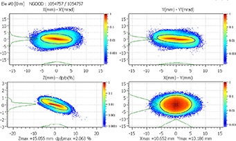
Figure 5. 6D phase space beam distribution of HEBT input beam.
Download figure:
Standard image High-resolution imageTable 1. Main beam parameters at the HEBT entrance.
| Parameter | Value at HEBT entrance (SRF exit) |
|---|---|
| Energy | 9 MeV |
| Current | 126.07 mA |
 x (rms-norm) x (rms-norm)
| 0.390 π mm · mrad |
|
y (rms-norm)
| 0.375 π mm · mrad |
|
z (rms-norm)
| 0.568 π mm · mrad |
| x size (rms) | 2.42 mm |
| y size (rms) | 2.91 mm |
| z size (rms) | 2.84 mm |
| p size (rms) | 6.14 º |
| W size (rms) | 61.22 keV |
The HEBT line design (positions and fields of magnets, locations of BPMs) was optimized, not only to obtain a smooth transverse rms size and a low emittance, but with special focus on keeping under control the halo produced by the huge space charge forces which may lead to larger beam extension and particle losses to the chamber walls. With this aim, the distance between focusing elements has been reduced as much as possible, leading to very short magnets and to the insertion of the corrector magnets, necessary for controlling the beam trajectory, in the iron yoke of the quadrupoles. Figure 6 shows a schematic layout of the HEBT. In this figure and in the rest of figures of this section, the horizontal axis represents the position in m along the beam direction, from the beginning of the HEBT line. The black line represents the beam stay clear radius defined as the minimum beam pipe internal radius to assure that no losses are present in the transport line, even considering alignment and power supply errors. The vacuum pipe aperture of each element has to be equal or higher than the beam stay clear radius. Although a beam transport without losses has been obtained in nominal conditions, a beam scraper (designed for a maximum power deposition of 900 W) has been installed in the last part of the HEBT line to avoid potential losses during failure situations in the chambers downstream, where access for maintenance will not be possible.
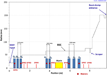
Figure 6. Schematic representation of the HEBT line elements.
Download figure:
Standard image High-resolution imageFrom these studies the quadrupole and dipole magnets specifications were obtained. They are summarized in table 2. Hard edge models for the quadrupoles magnetic fields have been used in the beam dynamics simulations. This simplification has been validated with calculations using the real field maps, which show, after a quadrupole retuning, negligible differences in the beam transport along the HEBT line.
Table 2. Magnet specifications and field gradients for the nominal configuration.
| Combined quadrupole and steerer magnets | |||||
| Quadrupole type | Name in HEBT line | Magnetic length (mm) | Aperture diameter (mm) | Max. Grad (T m−1) | Steerer field (G.m) |
| 1 | Q1-2-3 | 165 | 90 | 14.5 | 30 |
| 2 | Q4-5 | 150 | 136 | 8 | 30 |
| 3 | Q6-7-8 | 250 | 136 | 12.75 | 30 |
| Bending magnet | |||||
| Bending angle (º) | Aperture diameter (mm) | Bending radius (mm) | Integrated magnetic length (T · m) | ||
| 20 | 136 | 2000 | 0.2143 | ||
The rms envelopes along the HEBT for horizontal (x), vertical (y) and longitudinal (beam axis) directions (z) are shown in figure 7. A safe margin between total beam size extension and beam pipe aperture, can be seen in the particle density distribution in figure 8.

Figure 7. Rms envelope along the HEBT line.
Download figure:
Standard image High-resolution image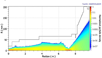
Figure 8. Particle density probability along the accelerator axis in nominal conditions.
Download figure:
Standard image High-resolution imageThe initial energy spread will induce an increase of the longitudinal size of the beam, debunching it quickly. The rms energy spread within the bunch is about 0.35% at the HEBT line input. At 7 m from the beginning of the HEBT line, bunches will start to overlap). Thanks to the compactness imposed in the beam direction, the total length of the line has been limited, being the bunch structure kept till the end of the line, after the last triplet. This is important as the debunching affects the performance of the last BPMs, which are used for the control of the beam centering at the BD and are therefore essential for the fulfillment of the beam requirements at the BD entrance (see section 3), figure 9 depicts the beam at the entrance of the BD, being notable its symmetry in both transverse directions.
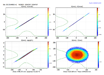
Figure 9. Beam distribution at the beam dump entrance in nominal conditions.
Download figure:
Standard image High-resolution image4.3. Error studies
4.3.1. Methodology.
The goal of the error studies is two-fold: to define the manufacturing tolerances of the magnets and of their power supplies and to evaluate the robustness of the HEBT line design as a whole with respect to manufacturing and positioning errors.
The following errors, concerning quadrupoles and dipole, have been introduced in the beam dynamics simulations:
- magnet displacement in directions transversal to the beam axis (x, y)
- magnet rotations along the three axes
- power supply errors
Two categories of errors have been considered: static and dynamic. The first one refers to constant or very slowly changing errors, producing a constant degradation of the beam quality. Their main consequence, the deviation of the beam trajectory from the center axis, can be corrected by using steerer magnets. As it has been explained in section 1, the HEBT line trajectory correction scheme relies on horizontal and vertical steering coils, associated with the downstream BPMs. As the HEBT line structure consists of grouped focusing elements separated by long straight drift sections, it is enough to correct the trajectory in these sections using two BPMs placed close to the two ends of each drift. The steerers, located in the quadrupoles 1, 3, 4, 5, 6 and 8 (see figure 6) will be tuned to introduce kicks that compensate the field errors and bring the average beam position to zero at the BPMs. This one-to-one correction scheme is intended to maintain the beam displacement from its center axis below acceptable values (mainly defined by the BD requirements, see section 3.2), using a maximum steerer integrated field of 30 G · m.
On the other hand, dynamic errors, representing very fast errors, being zero on average, have also been considered. These cause a jitter of beam parameters and can not be corrected. Power supply ripple is an example of dynamic errors.
One million of macroparticles have been used in the error simulations.
In a first step the sensitivity of the HEBT line to each type of error has been separately analysed to evaluate its individual contribution. For each element of the line, the amplitude of the error is randomly generated in a uniform distribution with given maximum values. Based on this analysis, an acceptable limit on each error (tolerance) is chosen, so that the effects on the trajectory and beam size deviations are similar for all error types and fulfill the HEBT line requirements (section 3.4). The obtained tolerances are presented in table 3.
Table 3. HEBT line static and dynamic errors for quadrupole and dipole magnets.
| Error | Static | Dynamic |
|---|---|---|
| Quadrupole gradient (%) | ±2 | ±0.1 |
| Quadrupole displacement (mm) | ±0.2 | ±0.01 |
| Quadrupole rotation (X,Y) (°) | ±0.9 | ±0.06 |
| Quadrupole rotation (Z) (°) | ±0.3 | ±0.06 |
| Dipole magnetic field (%) | ±0.1 | ±0.1 |
| Dipole displacement (mm) | ±1 | ±0.1 |
| Dipole rotation (X,Y) (°) | ±0.6 | ±0.06 |
| Dipole rotation (Z) (°) | ±0.6 | ±0.06 |
Also, an error on the BPM measurements (0.3 mm accuracy) has been considered taking into account the big aperture of the vacuum chamber and the fact that the beam will be debunched at the end of the line. Finally, as it will be explained in the next section, all errors within the given tolerances are combined simultaneously to validate this set of tolerances defined previously and to study the maximum beam size and overall degradation of the beam properties.
4.3.2. Static error analysis.
HEBT beam dynamics simulations were performed considering 500 different combinations of random alignment and power supply errors, uniformly distributed within the chosen tolerances (table 3). Figure 10 represents the particle density probability for combined errors and shows that the whole beam is always inside the beam stay clear limit. The orbit corrector integrated fields have reasonable values (lower than the 30 G · m design value) and the beam at the HEBT line output satisfies BD requirements.
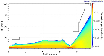
Figure 10. Particle density probability including magnet alignment and power supply static errors.
Download figure:
Standard image High-resolution imageThe rms beam position in both transverse directions is shown in figure 11. It is observed that the maximum deviation occurs at the end of the HEBT line (BD entrance—position 9.6 m in the figure 11).

Figure 11. Rms beam orbit position including magnet alignment and power supply static errors.
Download figure:
Standard image High-resolution image4.3.3. Dynamic error analysis.
The study of dynamic errors has been performed with 300 linacs, being the error magnitude a fraction of that chosen in the static errors studies (table 3). Since dynamic errors can not be corrected, steerers are not included in these simulations and orbit deviation increases as the beam goes through the line, leading to maximum orbit center deviation at the entrance of the BD (see figure 12).

Figure 12. Rms beam orbit position including magnet alignment and power supply dynamic errors.
Download figure:
Standard image High-resolution image4.3.4. Start-to-end errors.
Beam transportation from the start to the end of the accelerator was simulated to ensure the coherence of the different accelerator systems, to validate the defined magnet tolerances and characterize possible beam losses. Start-to-end simulations have also been carried out by tracking 106 macroparticles along 500 machines with different random sets of errors [16]. Some losses have been found along the HEBT line, occurring at many locations in one case over the 500 studied machines whereas in 5% of the cases there are losses at the dipole. However, the power lost is not significant. In the worst case, losses in the HEBT line are less than 2 W, except near the very end, at the location of the scraper, where losses go up to 5 W in one case over 500.
4.4. Studies of commissioning, tuning and accidental situations
In addition to the nominal operation, there will be some specific operation conditions requiring the HEBT quadrupoles tuning, as for instance, the commissioning or the emittance measurement with quad-scan techniques. A detailed study of these situations has been performed in order to establish the maximum quadrupole gradient variation such that no losses occur in the HEBT line, except in the beam scraper, and that the HEBT line output beam satisfies the BD requirements.
Statistic simulations (1000 linacs) have been performed by changing the quadrupole gradients according to a uniform distribution with a maximum value given. Two effects have been analyzed: beam losses along the HEBT line and beam modifications at the BD entrance. The maximum design value of power absorbed by the scraper leads to a limitation in the deviation of the quadrupole gradients from the calculated nominal values of 3.3% (see particle density probability in figure 13). On the other hand, the avoidance of beam size variations at the BD entrance larger than 30% imposes a more stringent limitation of the quadrupole gradient variations to 2.5%. This implies that tuning should be done in a controlled way, with steps between matched configurations smaller than this value.

Figure 13. Top: particle density probability plots along the beam trajectory for a 3% maximum deviation of magnetic field gradients with respect to the calculated values. Bottom: rms beam size at the beam dump entrance, for cases with 2% and 3% maximum variation of the magnetic field with respect to the nominal value.
Download figure:
Standard image High-resolution imageBeam losses in case of magnet failures have also been analysed [17]. Two cases of failure have been studied: failure of each element individually while all other ones stay at their nominal setting, and global failure of all the elements corresponding, for example, to a general electric breakdown. The assessment of such beam dynamics analysis during failure demands the Machine Protection System [18] to be designed so that, in case of sudden failure, the beam is stopped before the current in the quadrupoles in the high-energy part reach a value which differ ±5% from the nominal one. A reduction of the dipole current up to values of 85% of the nominal one leads to particles hitting the scraper whereas when the current reaches 70% of the nominal value, the beam is completely lost.
5. Other design substantiation studies
In this section the main studies performed for the definition of the LIPAc HEBT line design will be summarized.
Section 5.1 summarizes the calculations performed for the definition of vacuum sectors, number, location and characteristics of the pumping equipment and section 5.2 explains the assembly and alignment studies that were required for defining the design layout of the line. Section 5.3 summarizes the radiation calculations performed to define the radiation hardness requirements and to explore the feasibility of hands-on maintenance. The studies performed for the magnets design are not included here, as they will be explained elsewhere [5], being the main results summarized in section 6.2.
5.1. Pumping
5.1.1. Vacuum requirements.
The vacuum system must fulfill the following requirements and constraints:
- The maximum pressure allowed at the interface between the SRF linac and the HEBT line is 5 · 10−8 mbar.
- The system must be oil free to avoid contamination of the SRF linac.
- It should be optimized for hydrogen-deuterium gases extraction.
- The pumping ports must be located in the available space in the line which is very limited.
- Pumps must withstand the radiation environment as well as the presence of magnetic fields due to the proximity to the magnets. Magnetic field at the locations of pumps P3 and P4 (see figure 14), between the dipole and the quadrupoles from the doublet/last triplet, is around 20 mT.Total absorbed doses are maximum at the pump P5 (see table 6), closest to the BD, with estimated values of the order of 104 Gy at the end of the facility life time.
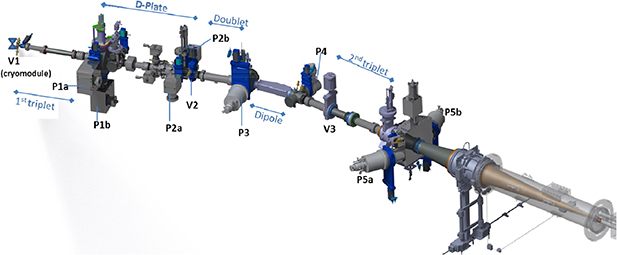
Figure 14. HEBT line showing vacuum sectors and elements.
Download figure:
Standard image High-resolution imageTo facilitate operation and maintenance, the line has been divided in three vacuum sectors (figure 14), separated by isolation valves:
The first one, from the gate valve at the SRF linac exit (V1) up to the end of the diagnostics plate (V2), must assure a vacuum level compatible with that of the linac. It must also protect the linac in the event of contamination from the HEBT line. For this purpose it includes a fast valve located close to V1.
The second sector, between V2 and the next gate valve (V3), plays the role of buffer zone between the BD and the high vacuum part; it shall allow decreasing the pressure from about 10–5 mbar (BD vicinity) to values of the order of 10–8 mbar at the beginning of the line.
The pumping system in the last sector, from the last valve before the BD cell wall (V3) up to the tip of the BD cone, must be sized to remove the high gas load coming from the interaction of the beam with the BD material.
5.1.2. Gas loads.
The gas loads in the HEBT beam tube are (1) the gas produced by the beam itself after impinging on the BD, (2) the outgassing from the walls (thermal and stimulated by energetic particle bombardment) and (3) beam losses along the line.
The deuteron beam is converted into deuterium gas by neutralization and recombination in molecules at the BD cone surface, representing by far the main gas load. For a current of 125 mA the gas rate produced is about 1.6 10–2 mbar · l · s−1. The BD copper thermal outgassing is more than two orders of magnitude lower than this load.
All HEBT vacuum facing materials, except the scraper, which has been made of aluminum, are stainless steel 316, 316L or 310. The lead shutter has been encased also in stainless steel to limit its outgassing. The outgassing composition for stainless steel is assumed to be mainly hydrogen [19]. A conservative value of stainless steel outgassing [20] is 10–10 mbar l s−1 cm−2. Taking into account uncertainties due to the beam induced-desorption, etc the vacuum calculations have been carried out also with an outgassing value of 10–9 mbar l s−1 cm−2. It can be observed that, despite the large area (around 7 m2), the total outgassing load is several orders of magnitude smaller than the gas load generated at the BD.
Concerning beam losses along the line, and considering the HEBT line design requirement of 1 W m−1 maximum beam loss, the corresponding gas load per unit length will be 1.4 10–8 mbar · l s−1 m−1. Thus the total gas load (for the 9.6 m long HEBT line) caused by the beam losses is more than two orders of magnitude lower than the outgassing load.
In summary, the system is dominated by the intense gas source from the BD, being the outgassing only relevant at the beginning of the line, near the interface between the HEBT line and the SRF linac.
5.1.3. Pumping equipment.
The main limitation for this pumping system is the large pumping speed required for deuterium (or for hydrogen during commissioning) using the space available at the beam chambers, which is very limited. Different pumping technologies were considered:
-
Turbomolecular pumps, which can reach low pressures (<10−10 mbar) but have some drawbacks:
- They would have to be backed by dry pumps, which for light species have a limited minimum achievable pressure.
- High speed pumps (high flange diameters) have low compression ratios for hydrogen (they need very low fore-vacuum pressure to reach the desired pressure). Also, the ratio pumping speed to flange diameter is too low for the HEBT needs
- Its electronic components are sensitive to radiation and to magnetic fields.
- Cryogenic pumps: These pumps have very high pumping speeds that can be maximized for certain species (i.e. hydrogen). As in the case of turbopumps, the magnetic field and the radiation in the vicinity of these pumps are limiting factors. To avoid damage and waste capacity, the vessel must be evacuated to a pressure lower than 10–3 mbar prior to starting pumping.
- Sputter-ion pumps: Combined with titanium sublimation, they can reach very high pumping speeds for hydrogen with very low final pressure. Before switching on this kind of pumps, the chamber has to be evacuated to a pressure lower than 10–5 mbar.
Taking these considerations into account the equipment chosen consists of ionic pumps combined with Ti sublimation at the beginning of the HEBT line (P1 and P2), because they give high pumping speed at very low pressure without mechanical components in motion, minimizing vibrations in the diagnostics plate, and cryogenic pumps (P3, P4 and P5) closer to the BD because of their excellent pumping speed. Turbomolecular pumps are only used for previous pumping before switching on the ionic and/or cryogenic pumps.
After several iterations, a selection of pumping locations, apertures and pumping velocities was done. The positions and naming of pumps are showed in figure 14. Pumps P1 and P2 are located at the D-plate, pumps P3 and P4 in the chambers before and after the dipole and pump P5 (which is duplicated) at the closest location to the BD, which is in the lead shutter chamber. The pump characteristics are listed in table 4.
Table 4. Pump characteristics used in the simulations and specific models finally procured.
| Type | Flange | Pumping speed (l s−1) | Model procured | Pumping speed (l s−1) for H2 of procured pumps | |
|---|---|---|---|---|---|
| 1 | Ionic + Ti sublimation | CF160 | 1800 | Gamma Vacuum 600 TV | 3470 |
| 2 | Ionic + Ti sublimation | CF100 | 1250 | Gamma Vacuum 150 TV | 2480 |
| 3 | Cryogenic | CF250 | 5000 | Sumitomo CP12+ adapter CF300-CF250 | 6950 |
| 4 | Cryogenic | CF160 | 1500 | Sumitomo CP8+ adapter CF200-CF160 | 2610 |
| 5 | Cryogenic | CF250 | 5000 | Sumitomo CP12+ adapter CF300-CF250 | 6950 |
5.1.4. Analysis.
The pressure profile calculations were carried out with a one-dimensional finite difference code using differential conductances.
In steady state, the pressure will be limited by the pumping speed, conductance of the device and the gas sources. For the analysis, the pumping speeds assumed at the pump flanges (table 4) were corrected taking into account the conductance of the isolation valves and adaptors that connect the pumps to the main chamber. To evaluate the conductance of the adaptor, a three-dimensional commercial code which uses thermal radiation analogy for the molecular flow calculation (COMSOL) was used [21].
The results for two scenarios with different outgassing levels are shown in figure 15.

Figure 15. Steady state pressure along HEBT line for different outgassing rates. Horizontal red line indicates the maximum pressure admitted at the SRF linac exit (5.10–8 mbar).
Download figure:
Standard image High-resolution imageAn independent analysis using TPMC methods (with the code MOLFLOW + [22]) was done as well (figure 16), showing a good agreement with the previous results. Calculations were done also for heavy gases (A = 28), to check the feasibility of using gas injection if needed for calibration of the FPM. The only source being the outgassing of the materials, the obtained pressure is very low along the whole line, in the order of 10–10 mbar. It is concluded that there is margin for injecting gas, if needed, at the level of the D-plate.
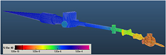
Figure 16. Results of simulations with MOLFLOW+. Pressure along the HEBT line (mbar) during beam operation at full power.
Download figure:
Standard image High-resolution imageThe last cryopump (P5), situated right before the BD cell at the lead shutter chamber, will receive most of the gas load. Given the typical capacities for these pumps (the capacity for hydrogen of the model finally procured is 50 bar · l), it will become saturated after more than 30 d of full power operation. However, given the lack of experience with the operation of this high current accelerator, it has been thought convenient to add a second identical pump at the same chamber in a symmetrical position. With this configuration continuous pumping is assured, as it allows the regeneration in one pump while the other one is still pumping. Simultaneous pumping would be also possible, increasing the total pumping speed if needed. Pumps P1 and P2 have also been duplicated to have additional pumping margin in the proximity of the SRF linac.
5.2. Assembly and alignment
The HEBT line magnets and the vacuum chambers containing diagnostics need to be positioned with high accuracy for allowing a proper beam transmission with the expected characteristics and with minimum losses, as well as an accurate beam characterization. The admissible tolerances in the positioning of the magnets (a combination of manufacturing and alignment tolerances) were obtained from the beam dynamics studies and are given in table 3. Typical alignment tolerances of diagnostics are of the order of ±0.1 mm. The vacuum chambers with transverse sizes close to the beam stay clear diameter should also be located with accuracy, to avoid invading the beam stay clear region. The compliance of the alignment tolerances requires the fulfillment of manufacturing tolerances in the individual components and a correct layout of supports and bellows to allow the fine positioning of the vacuum chambers.
Several bellows are required to absorb the misalignment of the beam tubes caused by imperfections during manufacturing or assembly and to make possible the alignment of those chambers which require a fine positioning. The bellows will also absorb thermal expansions during beam operation. Due to the space restrictions in axial direction, it has not been possible to provide a dedicated alignment system to each diagnostic, specially at the last part of the line, where fluorescence and IPMs, a SEM grid and a BPM form a rigid assembly. The same occurs in other parts of the line, like at the dipole region, where bellows could not be inserted between the dipole tube and neighbouring chambers due to lack of space.
Apart from the bellows inside the D-plate and those located transversally to allow the movement of internal elements like the slits and the lead shutter, a total of 10 bellows have been included along the HEBT line. The locations of the bellows and of the tube supports have been chosen to allow the positioning of the elements with the required accuracy. An estimation of the maximum deviation of the different beam line stretches between bellows from their theoretical position was done (see table 5). For this estimation, medium-grade manufacturing tolerances according to norm ISO 2768, were considered. The bellows characteristics (type and number of convolutions) were chosen to provide enough flexibility to absorb these maximum deviations.
Table 5. Maximum deviation estimation of the different HEBT beam tube stretches attributed to manufacturing errors. Names according to figure 20.
| Stretch | Deviation | ||
|---|---|---|---|
| Axial (±mm) | Angular (±º) | Transversal (±mm) | |
| 0-HBP01 | 0.5 | 0.5 | 0.6 |
| HBP01-Dplate | 0.8 | 0.3 | 0.4 |
| Dplate-HBP02 | 1.3 | 0.3 | 1 |
| HBP02-Slit chamber | 0.5 | 0.3 | 0.2 |
| Slit chamber-HBP03 | 1.2 | 0.3 | 0.8 |
| HBP03-HBP04 | 1.6 | 0.17 | 1.2 |
| HBP04-SEM grid/HBP05 | 0.8 | 0.3 | 0.4 |
| HBP05- Tube inside BD cell wall | 1.2 | 0.17 | 1.6 |
| Tube inside BD cell wall-BD cartridge | 5 | 0.57 | 4.5 |
Table 6. Specified maximum absorbed radiation doses at the vacuum system and other HEBT elements.
| Component | Absorbed Radiation dose (Gy) |
|---|---|
| Valves between cryopumps and line | 106 |
| Fast valve | 104 |
| Valves separating vacuum sectors in the line | 108 |
| Cryopumps | 104 |
| Rest of vacuum equipment inside the vault | 103 |
| Lead shutter actuator | 105 |
| Quadrupoles and dipole | 1.25 105 |
Due to the small available space in the beam axis direction, to provide the required flexibility, the bellows must be of the edge-welded type. The only exception is the last one, connecting the line to the BD cartridge [9]. This bellow could experience some heating due to beam losses and to radiation from the interaction between the beam and the gas inside the tube. Therefore, given that the residual radiation in this part of the line prevents any replacement, a hydroformed bellow (less flexible but more robust) was chosen in this case.
Given that the bellows convolutions are very thin and following recommendations by experts with experience in the operation of the high intensity LEDA accelerator [23], a cylindrical protection sleeve has been included in the interior of many of them to avoid their overheating. This interior sleeve could be indirectly cooled at the flange where it is connected. Figure 17 shows a section of one of the HEBT bellows, where the protecting sleeve can be seen.

Figure 17. Detail of one of the HEBT BPMs, showing the inner sleeve of the bellows.
Download figure:
Standard image High-resolution imageThe alignment of the HEBT line will be performed during installation on-site using a laser tracker. For this purpose, surfaces for installing holders for corner cube reflectors must be machined in the chambers and magnets.
Dedicated supports for the magnets and for the chambers containing diagnostics allow their positioning with six degrees of freedom (translation and rotation in the three axes). The support tuning screws have fine pitches, between 0.5 and 2 mm depending on the component, to allow a fine positioning resolution.
5.3. Radiation issues
The accelerator will operate under a radiation environment originated as a consequence of the interaction of the beam particles with the materials. At the HEBT region, radiation is dominated by the neutrons and gammas originated at the BD, with additional smaller contributions from the distributed particle losses along the line and from the beam interaction at intercepting elements like the scraper.
During beam-off periods residual radiation, due to the activation of accelerator materials, will remain. Calculations of residual doses have been done to check the feasibility of manual maintenance [8, 24].
The knowledge of the absorbed and residual dose rates, presented in the following subsections, has been decisive for the definition of the layout and materials of the different systems (cooling, vacuum, instrumentation and control, etc.). The most sensitive components and those requiring maintenance were located in zones with lower radiation (e.g. cooling instrumentation located mostly outside the vault, electronics for instrumentation and valves have been placed far from the beam line). Radiation resistance requirements have been specified for components and limitations in the impurity content of the materials have been imposed to minimize their activation.
5.3.1. Absorbed doses at the HEBT line during accelerator operation.
All the HEBT components have been designed taking into account the radiation environment under which they should operate. Special care has been taken in the selection of non-metallic materials (valve seats and seals in water and pneumatic circuits, isolators in magnets, etc.).
Absorbed doses after 6 months of continuous full power operation were calculated at the region occupied by the HEBT components for the materials of interest (stainless steel and different plastics). As the main radiation source is that generated at the BD, the elements of the line after the dipole, which are closer to the BD and aligned with its axis, are the most irradiated.
Figure 18 shows the absorbed neutron and photon dose maps (for polyethylene) at the equatorial plane of the accelerator in this region. z represents the coordinate along the beam axis. As expected, radiation levels increase when approaching the BD. At a given z, the radiation level is highest at the beam axis and decreases with the distance from it. Figure 19 shows the absorbed dose values for along the line, at a distance of 32.5 cm from the beam axis. Data in the region near the dipole are not shown as the dose rates there are not symmetrical around the beam axis.
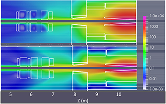
Figure 18. Photon (up) and neutron (down) absorbed dose rate maps in Gy h−1 during full power accelerator operation in the HEBT line after the dipole (located at z = 4.73 m) and the beam dump.
Download figure:
Standard image High-resolution image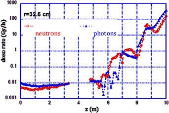
Figure 19. Absorbed doses along the HEBT line for polyethylene (for reference, inflexion point of beam axis at dipole is at z = 4.7 m and beam dump entrance is at z = 9.4 m).
Download figure:
Standard image High-resolution image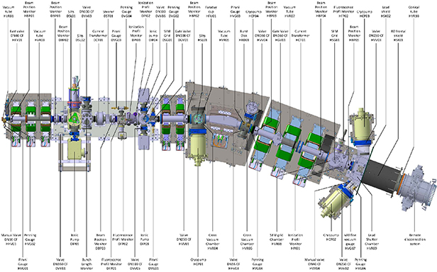
Figure 20. Top view of the 3D model of HEBT line, showing the names of the beam chambers and diagnostics.
Download figure:
Standard image High-resolution imageThese data have been used to specify the radiation resistance requirements of the different components and systems. As an example, table 6 shows the radiation requirements included in the technical specifications of different components of the vacuum system, which take into account the results obtained plus a significant margin.
5.3.2. Dose rates during maintenance.
As it was explained in section 3.4, a requirement of the LIPAc HEBT line and of the whole accelerator is that maintenance operations be hands-on. Apart from unforeseen maintenance (repair) operations, some scheduled maintenance will also take place. Some examples of elements which will need maintenance or replacement during the facility lifetime are the following:
- Vacuum pumps: some components will need replacement after several (tens of thousands) hours.
- Vacuum valves and fast valve
- Magnets instrumentation and plastic connections on the lead shutter action mechanism will also require replacement.
To check the feasibility of manual maintenance, an analysis of the dose rates when the beam is off has been done following the methodology described in [24] and [8]. In this situation, the only radiation present is that coming from the components of the accelerator which have become activated by the interaction with the beam and with the neutrons arising from the deuteron-materials interactions. Most of the activated products decay rapidly, hence the dose can be reduced by simply delaying the personnel entrance. However, there are some isotopes with longer decay times (such as the Zn65, t1/2 = 243.8 d), produced at the beam dump by deuteron interaction with the copper, or the Co60 (t1/2 = 5.27 years) which comes from cobalt as impurity, always present in the steel and other metallic materials.
The residual dose rates at the HEBT vicinity are due to the activation of the concrete walls (of the vault and BD cell), the HEBT elements and the BD cartridge.
The activation of the walls by the neutron flux present during accelerator operation, produces residual dose rates in the vault, right after accelerator shutdown, of around 400 μSv h−1. During the first days after shutdown the contribution of the walls is dominated by the decay of the Na24 (t1/2 = 15 h) produced by neutron capture in the Na naturally present in the concrete. This forces to a waiting time of the personnel before entering the vault of several days (after one week cooling time the dose due to the walls decreases up to 1–2 μSv h−1).
The neutrons generated at the BD are the main responsible for the activation of the HEBT elements. The activation due to deuteron losses is negligible compared to it. Therefore the most activated components are those closer to the BD like the quadrupoles of the second triplet (the isotopes contributing most to the residual doses after one day cooling are the Mn54 and the Fe59 generated in the iron yoke). A special case is the scraper which due to its function will be activated by the deuterons from the beam. It has been made of aluminium to minimize its activation.
BD activation (Zn 65) will contribute with an additional dose rate which, of less than 4 μSv h−1 after 1 week cooling [8]. Total dose rates in any case are well below the 25 μSv h−1 limit for unrestricted presence of workers.
6. Detailed design and manufacturing
This section deals with the detailed design, manufacturing and acceptance tests of the different systems and components of the HEBT line.
6.1. Vacuum chambers
The HEBT line includes a total of 28 chambers along the beam direction, and other small elements located transversally which do not see the beam. Besides those of the D-plate, nine of these chambers contain beam diagnostics (5 BPMs, 1 slit, 1 IPM, 1 ACCT, 1 multi-diagnostic chamber containing ionization and FPMs and a SEM grid). Figure 20 is a top view of the HEBT line 3D model, where the magnets have been hidden, showing the beam chambers and their names.
The chambers at the end of the HEBT line have a larger complexity due to their size and working environment (high radiation due to the BD proximity). These are:
- The lead shutter chamber, which contains also the HEBT scraper and has been described in detail in a previous article [8].
- The conical tube for the BD cell wall passage, which is surrounded by removable shield elements and it is also described in [8].
- The two bellows of 400 mm diameter joined by an articulated collar that allows the BD cartridge disconnection from more than 2 m distance (from outside the BD shield). This system has been explained in other article [9].
Most of the beam chambers have been manufactured at CIEMAT workshops. The lead shutter chamber and the conical tube were fabricated by the company Ramem S.A (Madrid, Spain), and other chambers were manufactured by CEA and Kurt J. Lesker. The bellows needed (except for the last one, at the interface with the BD) were procured from COMVAT company, who also performed their welding to the chambers. The last bellows (hydroformed) was procured from Witzenmann.
All chambers have been made of stainless steel 316, 316 l or 310. Special care has been taken to assure low magnetic permeability in the material of those chambers in the vicinity of the magnets, to avoid distorting the generated magnetic field distribution.
The detailed design was driven largely by the space restrictions in longitudinal direction, which in many occasions have led to special designs (welded joints instead of bolted ones, narrow flanges, threaded holes and screws in the flanges instead of bolts and nuts, etc.).
The clearance between chambers and magnets is small (between 1 and 1.5 mm). The reason is that, to minimize their size and cost, the magnets have been designed to produce the necessary field with the minimum current. This led to the definition of a minimum aperture in the poles, equal to the beam stay clear size plus the thickness of the beam tube plus the clearance.
In the case of the dipole beam chamber, it was decided to include a copper block with the aim of absorbing the energy of a non-steered beam in case of a failure in the dipole, during the few ms required to detect the problem and shut down the beam [18]. The requirement of including this 'beam dump' (which came after the dipole design had been frozen) led to a change of the dipole beam chamber geometry, from a cylindrical curved tube to a prismatic one. As this last geometry is more prone to buckling when vacuum is made in its interior, it required a larger thickness (5 mm), and the margin between aperture (136 mm) and beam stay clear diameter (130 mm) happened to be too small. A design with reduced thickness only in a region along the beam trajectory was done (see figure 21), coping with the two opposing requirements of mechanical stability under vacuum forces and maintaining the beam stay clear region. Figure 21 shows pictures of this chamber, while figure 22 shows the maximum deformation (0.3 mm) and the maximum equivalent stress (74.7 MPa) generated by the vacuum forces in it.

Figure 21. Top: Dipole chamber drawing. Bottom left: picture of manufactured chamber showing the copper block. Bottom right: interior of the dipole chamber seen from the beam exit flange (copper block not shown but just its attachments). The groove following the beam trajectory can be observed in the upper and lower plates.
Download figure:
Standard image High-resolution image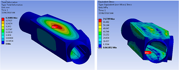
Figure 22. Deformations and stresses in the evacuated dipole chamber.
Download figure:
Standard image High-resolution imageMedium grade tolerances were required in general. Additional specific tolerances of 1 up to a few tenths of mm were defined in some chambers considering their position in the line, distance to other elements (e.g. magnet poles) and alignment requirements of the diagnostics mounted on them. Metrology checks of the specific tolerances indicated in the manufacturing drawings were done with a 3D measuring machine after completion of manufacturing and in some cases at intermediate stages (e.g. the BPM electrodes geometry were checked before performing the final welds, when the electrodes were still accessible to the 3D measuring machine—see figure 23).
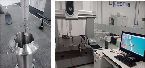
Figure 23. Metrology of HBPM1.
Download figure:
Standard image High-resolution imageRotatable flanges were included in several chambers to ease their installation. All vacuum joints are metallic. Most of them are based on CF copper gaskets whereas special helicoflex gaskets are used in the high radiation region—high diameter bellows inside the beam dump cell—and in other specific places (rectangular flanges at the lead shutter actuator and dipole BD).
All interior surfaces of the chambers, which will be exposed to vacuum, were cleaned in an ultrasonic bath with alkaline detergent, rinsed with demineralized water and dried with nitrogen.
He leak tests were performed in all the chambers with an acceptance value of 10–10 mbar · l s−1.
6.2. Magnets
The HEBT line includes nine room temperature magnets -eight quadrupoles and one dipole- for beam handling, located as shown in figure 2. Out of the eight quadrupoles, six of them include -in the same iron yoke- a couple (horizontal-vertical) of corrector magnets. Apart from the presence of corrector coils, the magnets of each group (the two triplets and the doublet) are identical.
The magnets design has considered the specifications determined by the beam dynamic studies (tables 2 and 3), as well as the available space in the line and the presence of ionizing radiation. All magnets can be separated in upper and lower halves, to allow the installation of the beam tube.
The quadrupole coil geometries have been carefully chosen to optimize the field quality but also to minimize the longitudinal dimension and the transverse size of the magnets. While the coils of first triplet and doublet magnets are planar, that is, their cross-section does not vary with the radial coordinate, those of the largest magnets, in the 2nd triplet, have been designed with a 30º angle, following the pole shape, with the aim of minimizing the iron saturation. A picture of one of these magnets is shown in figure 24.
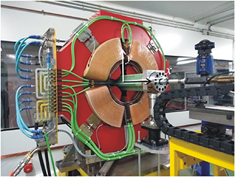
Figure 24. Magnet HMA06, which belongs to the second triplet and contains a quadrupole, a horizontal steerer and a vertical steerer, during the magnetic tests at ALBA-CELLS magnetic laboratory.
Download figure:
Standard image High-resolution imageRegarding field quality requirements, the harmonic content of the quadrupole field has been specified to be lower than 0.01% of the principal harmonic and the magnetic center and angular deviations have been specified to be less than 100 μm and 2.5 mrad respectively (a factor of 2 stricter than the deviations validated with the beam dynamics studies—see table 3—, to leave margin for alignment tolerances). These requirements imposed a global shape tolerance in the obtained iron pole profile shape (after machining the four poles independently and fixing them together) of ±2 hundredths of a millimeter. Those tolerances were achieved by carefully shaping the iron poles by electro-discharge machining and positioning the poles by a system of holes and dowel pins to obtain enough accuracy and reproducibility.
Although the configuration with nested quadrupole and steerer coils in the same yoke leads to a high sextupolar component in the steerer fields, simulations have shown a correct beam transport. This configuration leads also to a dependence of the steerer field with the quadrupole field (quad-steerer coupling), because iron saturation reduces the effect of the steering coils when the quadrupole is powered. However, at nominal quadrupole current this reduction is only of 2%.
To bend the beam 20º, an H-type dipole, designed for an integrated field of 0.2154 T · m, with 0.33 T vertical field, was designed and manufactured. As in other elements of the HEBT line, longitudinal length restrictions led to a compact design which implied technical difficulties, such as, the relevance of 3D effects to be considered in the magnetic simulations (during the design phase), and special efforts on winding the coils and shaping the coil terminals (during the manufacturing phase).
Figure 25 shows the lower half of the HEBT dipole at the factory where it was manufactured. This magnet is also shown at the left of figure 29(a), during the integration tests at CIEMAT. The design current in the dipole is 100.6 A. Each coil is made of 10 double pancakes, with ten parallel water circuits, each of them cooling a couple of neighbouring pancakes.

Figure 25. Lower half of the LIPAc HEBT dipole.
Download figure:
Standard image High-resolution imageA field homogeneity better than 0.1% was specified, to cope with the beam dynamics requirements. To fulfill this objective, 2D and 3D calculations of the pole profile were done leading to a design with shims and to tolerances better than 0.1 mm on the iron poles machining. Rogowski profiles were also included to decrease saturation and fringe fields. References were machined at the top iron surface to align the dipole, taking into account the effect of the real field distribution, including fringe fields, on the particle trajectories.
Due to the presence of radiation, the materials employed in the magnet manufacturing, specially those used as electrical insulators in the coils, and the instrumentation (thermal switches and associated cables and connectors) were carefully selected. The technique of vacuum pressure impregnation of a mixture of epoxy resin into the copper coils wrapped by fiberglass tape was employed.
The magnets have been manufactured by the company Elytt Energy. They were fully characterized by magnetic tests at the Magnetic Laboratory of the ALBA Synchrotron in Barcelona [25], where their magnetic response was measured at different currents corresponding to the operational points of nominal H+ and D+ beams (figure 24). Linearity and saturation characteristics were checked, as well as the integrated fields of quadrupoles, steerers and dipole. All these characteristics as well as the field quality requirements were shown to be as specified for all magnets.
Independent power supplies have been provided for each quadrupole and corrector magnet. Those feeding the magnets of each group are identical. To fulfill the requirements obtained from the beam dynamics error analysis of the HEBT line (table 3), the power supplies for the quadrupoles and dipole were required to have a precision (including all the possible sources of current variation: ripple, temperature or any other cause) better than 300 ppm, referred to the current set-point, in all the range from 10% to 100% of the design current. The steerers power supplies are of the four-quadrant type, with a specified precision value of 600 ppm. All the power supply models, manufactured by Sigmaphi Electronics, underwent successful acceptance tests at the factory, first with a test load, and afterwards with the LIPAc HEBT magnets (figure 26).
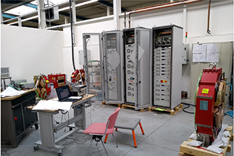
Figure 26. Magnet power supplies during tests at the factory with the real loads.
Download figure:
Standard image High-resolution image6.3. Support frames
The line has been divided in six assemblies with independent support frames: first triplet, D-plate, doublet, dipole, last triplet and diagnostics & lead shutter. Each support frame holds all the elements in a given assembly: the vacuum chambers, magnets, diagnostics and vacuum components. Their design is similar to that of the MEBT and D-plate supports [26].
To bear the mechanical loads, the supports consist of a structural global frame made of austenitic stainless steel 304 on which several supports of the same material for the individual components are mounted. The common frame and the individual supports can be displaced to move the component with six degrees of freedom (translation and rotation in three axes). As shown in figure 27, the feet of the common frame can be adjusted in vertical position by means of a levelling set with fine tuning pitch and in horizontal position by four fine pitch screws. In addition, levelling washers allow the tilting of the upper plate of the feet, and consequently, the rotation in the three axes. Each individual component support has a similar design with several vertical and horizontal fine pitch screws allowing the position in the three axes, with levelling washers allowing the tilting of the upper plate. To allow their alignment with a laser tracker, holes for Corner Cube Reflector holders have been machined in several positions of the support frames.

Figure 27. Support frame for dipole and neighbouring elements.
Download figure:
Standard image High-resolution imageGeometrical tolerances (flatness, parallelism) were demanded in the machining of surfaces and holes for the alignment holders and also in those surfaces in direct contact with the HEBT elements (plates for dipole, quadrupoles or vacuum chambers) as well as in specific regions where assembly tolerances are tight, like the three individual supports mounted on the global frame of the dipole subassembly (figure 27).
The support frames have to withstand the weight of the components with small deformations. In addition, the seismic requirements impose a 0.4 g horizontal acceleration and a 0.2 g vertical acceleration applied to each of the components. All the support frames have been analysed with Structural Finite Element Method simulations and the results show that they withstand the loads imposed. The dimensioning of the screws of the frames has also been checked in these simulations.
A temporal support was manufactured to hold the larger flange of the conical tube for the BD cell wall passage (HVR10 in figure 20) from the inside of the BD cell during assembly. This frame can be seen in figure 28. This chamber and its surrounding shield (at the left of the picture) will be supported on the other end on the diagnostics&lead shutter support frame, which has wheels that allow its displacement during the insertion of these pieces in the BD cell wall.
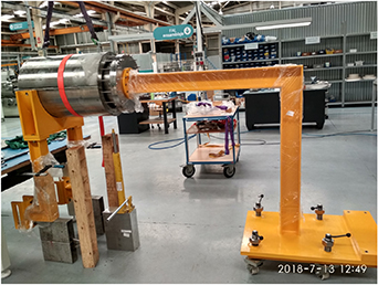
Figure 28. Temporal support structures for the installation of the conical tube through the beam dump cell wall. The yellow structure on the right will hold the conical tube from the inside of the beam dump cell. The yellow pieces on the left will be supported on the lead shutter support frame.
Download figure:
Standard image High-resolution image
Figure 29. (a) The last three subassemblies of the HEBT line partially mounted at CIEMAT premises for assembly tests. The upper halves of the second triplet magnets have been removed for working in the beam tube. (b) The first triplet subassembly of the HEBT line with the tube the magnets partially installed. (c) CIEMAT team contributing to the design and manufacturing of the HEBT line.
Download figure:
Standard image High-resolution image
6.4. Vacuum system and components
Concerning the vacuum valves, due to the radiation working environment, all-metal models (VAT Series 48) have been selected for those installed in the main line, separating the different vacuum sectors (V1, V2 and V3 in figure 14).
The pumps are connected to the beam chambers via automatic gate valves VAT series 10. These valves have been modified with respect to the standard ones, with the objective of accomplishing the radiation specifications stated in table 6. The changes concern the actuator, solenoid, position indicator and also the gate gasket which is made of EPDM.
As it has been mentioned in 5.1, at the interface between the HEBT line and the SRF linac a fast valve has been installed for protecting the linac from an eventual vacuum loss in the HEBT line. A valve with the minimum closing time available in the market was selected: VAT series 75 (CF40). This valve is activated when the signal from a dedicated pressure sensor of Pirani type located at the end of the line—in the lead shutter chamber—exceeds a pre-established value. Although the closing time of the valve after receiving the signal is only 10 ms, due to the long (90 m) cables, the total time since the manometer reaches the established limit until the valve is completely closed is 18.5 ms. This is just enough to prevent a pressure increase due to a water leak at the BD from reaching the SRF linac.
Ports for measuring the pressure and for venting/pumping were included in the small space between the isolation valve V1 at the beginning of the line and the fast valve. They are needed for opening of the valves to restart operation after a closure of the fast valve.
In each vacuum sector pressure sensors for the low-medium pressure range (Pirani type, model TPR018 from Pfeiffer) and for the high vacuum range (Penning type, model IKR060 from Pfeiffer) have been installed to characterize the vacuum state of the line in the full range of expected pressures.
The pump models finally procured are shown in table 4 (pump locations can be seen in figure 14): ionic pumps with Titanium Sublimation filaments and ambient sputter shield, models 600 TV and 150 TV from Gamma Vacuum, for pump groups 1 and 2, cryopump CP12 for P3 and P5 and CP8 for P4, both models from Sumitomo. The cryopumps include the safety features needed for the operation with deuterium (safety valve to avoid deuterium accumulation in case of power outage). The radiation requirement led to some modifications of the standard products, substituting the usual temperature sensor (Si diode) by a special one. Controllers and compressors for the cryopumps are located outside the accelerator vault.
6.5. Control system
The HEBT radiation environment makes necessary a robust remote control with different subsystems for controlling and monitoring the operation and the status of the components.
The main objective of the HEBT line and D-plate control systems is to provide all necessary information for the HEBT line to properly perform its function of transporting the beam from the SRF linac up to the BD fulfilling all the established requirements. It must guarantee a successful operation from the commissioning phases up to the full power operation. For this purpose, it must provide a fast communication of variables to the Central Control System (CCS) and it must communicate with the Machine Protection and Personal Protection Systems of the accelerator [18]. It processes more than 1600 variables involving more than 480 cables which amount to a total length of multi-wire cable of around 21 km.
The system is based on EPICS, a set of open Source software tools, under LINUX Input/Output Controller (IOC). The Human Machine Interfaces or Operator Interfaces are based on Control System Studio. The hardware is distributed in six seismic cubicles with EMC (electromagnetic compatibility) enclosures (two cubicles for control hardware, two cubicles for vacuum hardware and two cubicles for diagnostics). Some of them were pre-assembled at CIEMAT facilities before the delivery to the LIPAc facility.
The signals are centralized and controlled by a Siemens programmable logic controller (PLC), S7-300, and distributed by Local Area Network to the EPICS CCS. Additionally, an independent controller specially robust to failures called Safety Relay is included (Modular Safety Systems SIRIUS 3RK3 from Siemens).
The digital and analogic inputs/outputs are distributed inside the control system depending on its function: monitoring, safety&protection or beam diagnosis. Signals for monitoring and diagnosis are sent to the main PLC, where processes with timing requirements and complex logic functions are run. The signals going to or coming from the Machine Protection or Personnel Protection Systems are centralized in the safety Relay, being totally independent of the PLC process.
The main PLC distributes the signals and variables to the IOC, and provides bidirectional communication with the peripheral components, through different communication protocols (ETH, Profibus, Profinet).
7. Integration tests/lessons learned
The six subassemblies of the HEBT line were mounted at CIEMAT premises in Madrid before their shipment to the LIPAc site in Rokkasho. Figure 29 shows three images of different subassemblies of the HEBT line that were mounted during the year 2018.
The objectives of the integration tests were:
- Check any mechanical interferences between components or details that should be corrected. In some cases, additional machining of surfaces and new welding activities were required. The HEBT line is made of hundreds of pieces, manufactured and procured in different places, along several years and under different contracts. Therefore some mismatches and errors occurred, which were detected and corrected during these tests.
- Try to minimize the time required for assembly at the final location in the LIPAc site, where, typically, parallel activities are being performed for the installation and commissioning phases and the general schedule and permanence inside the vault is limited.
- Define in a precise way the HEBT installation procedure, to be transferred to the team at LIPAc site, and prepare any special tool required (due normally to the limited space between components).
- Produce a comprehensive list of components to be shipped to the LIPAc site (hundreds of references were managed to complete the HEBT line).
As a consequence of the integration activities of the different components of the HEBT line at CIEMAT premises, some improvements and corrections in the chambers and/or supports were proposed and implemented. Some of the lessons learned during the integration activity at CIEMAT were the following:
- The convenience of the use of auxiliary elements to protect the delicate surfaces of the magnet iron poles during installation of the stainless steel beam tube (clearances of a 1–1.5 mm).
- The 3D mockup was very useful for checking the mechanical interfaces, but in some cases small discrepancies between the manufactured component and the model appeared that, considering the small clearance between components, prevented the assembly of the components or limited their alignment range. Most of these discrepancies occurred in the routing of the magnets rigid cables. To avoid the observed interferences, some tube supports were redesigned and corrected.
- The integration activity previous to transfer the components to the LIPAc site, was time consuming, but it was revealed as fundamental to gain experience with the HEBT line and to produce a detailed and realistic assembly procedure.
8. Conclusions/summary
The design and manufacturing of the LIPAc HEBT line, described in this article, has been finished. The equipment is presently at the LIPAc site in Japan. Installation is almost complete and commissioning with a 5 MeV beam is expected to take place during 2020.
The upcoming operation experience of the HEBT line integrated in the LIPAc accelerator will be valuable to validate the choices made and to improve the design and manufacturing of future transport lines of high current continuous ion beams, and particularly, that of IFMIF.
Acknowledgments
This work has been supported by the Spanish Government in the frame of the Broader Approach Agreement (Spanish BOE n14, p 1988).
The authors thank the Fusion Department Workshop, where most of beam chambers and support frames were manufactured as well as CIEMAT General Workshop.
The views and opinions expressed herein do not necessarily reflect those of the European Commission, Fusion for Energy, the authors' home institutions or research funders. The authors have confirmed that any identifiable participants in this study have given their consent for publication