


Abstract
A model is formulated to make a first estimate of the maximum tolerable power of liquid lithium (Li) divertor targets, and to gain insight into their behaviour in terms of Li loss rate and surface temperature. The model, formulated as a simple analytical expression, states that the incoming power is balanced by heat conduction through the target and by the Li which dissipates energy via evaporation, radiation and ion-neutral friction. A target is considered to fail when the net Li loss flux from the surface exceeds the available supply. The model is evaluated over a range of input parameters: Li supply rate, surface layer thickness, redeposition coefficient, and dissipated energy per Li particle lost to the plasma. Based on the results, first, surface temperature locking is expected above a deposited power of ∼10 MW m−2. Second, Li targets are expected to be extremely robust against power deposited during short transient events. A surface layer thickness of 50 micron is sufficient to withstand 60 MJ m−2 vertical displacement events or 20 MJ m−2 disruptions.
Export citation and abstract BibTeX RIS
1. Introduction
Liquid metal (LM) divertor solutions have often been proposed [1–5] as they potentially address issues with existing solid tungsten (W) divertors. Important arguments for this claim are: first, the lifetime of a solid W divertor is limited by erosion [6], whereas a liquid metal target can be replenished [3]. Second, liquid lithium (LL) specifically can retain up to 100% of incoming hydrogen [7], which could lead to significantly improved plasma performance as experimentally observed with LL in NSTX and CDX-U [8, 9]. The downside is that, unless retention can be prevented, fast circulation and filtering of lithium (Li) will be unavoidable to meet tritium inventory requirements, or high temperature regimes as considered in this work have to be used to prevent retention [10]. Third, the topic of this letter, in the case of the monoblock divertor design for ITER the power handling limit is only just above the operating point. Recent work shows melting of the monoblock edges is most likely unavoidable and that the safety margin for heat load control is extremely small [11]. Better power handling is expected for LM targets due to so called 'vapor shielding' [3, 12, 13]. This phenomenon has long been studied for solid materials (e.g. the 'virtual limiter' in [14] or more recently [15]); though, only the LM the effect can be used without permanently damaging the divertor. However, the exact power handling limit has not yet been found. All these issues are critical factors for the feasibility of commercial fusion plants.
In this work, a model is formulated to gain insight into the behavior of LL targets in terms of Li loss rate and surface temperature, and to make a first estimate of the maximum tolerable power, beyond which components will be damaged. The model is based on theory discussed in section 2. The model itself is presented in section 3 and considers a generalized target design, which is regarded to fail when the Li on the plasma facing surface (PFS) is depleted. Discussion and conclusion follow in sections 4 and 5 respectively.
2. Theory
Li that is removed from the PFS dissipates energy in the plasma. This is an important contribution to the power handling capabilities of LL components. The work presented in [16], provides us with the energy dissipated per Li particle in the plasma,  . This parameter is sensitive to the particle residence time in the plasma, τ, the electron density,
  , and most importantly
  .
.
The electron temperature can vary strongly throughout the plasma. Close to the divertor in detached scenarios  is in the range of 1–10 eV [17, 18], which puts
  in the order of 5–10 eV. Whereas around the midplane in the SOL,
  is expected to be in the order of a few hundreds of eV [16], and also during transients events such as ELMs,
  can exceed 100 eV as measured and modeled for JET [19]. Correspondingly,
  could be optimistically estimated as 300 eV. The present work considers
  of 5, 50, and 500 eV. Though the latter is an overestimate, it is chosen to be consistent with a logarithmic scale.
Lastly, we must consider redeposition. A large fraction of the lost Li is expected to be ionized within the sheath region [20], and will be promptly redeposited. On top of that, Li that is not promptly redeposited and escapes the sheath region can still be redeposited due to, e.g., momentum exchange with the incoming plasma flux. In [21] it is suggested that the total redeposition fraction R in fusion relevant conditions is >0.99. Though, below  eV this could drop even to R < 0.1. One can imagine that in the case of prompt redeposition there is no time for the collisional radiative process that results in
  to be dissipated. While not all redeposition is prompt redeposition, for practical purposes this letter will assume that all redeposited particles are indeed promptly redeposited, and therefore
  will only be dissipated by the permanently lost particles which are described by the net loss rate
  . Effectively, this is a worst-case assumption.
3. Power handling model
A generalized divertor target is considered which consists of a W substrate which is cooled on the back side. To allow comparison to the ITER monoblocks the temperature of the coolant and the effective thermal conductance of the complete target are taken  120 °C and
  W m−2 K−1, as derived from [22]. On the W sits a Li layer the thermal resistance of which is neglected due to its low thickness. Convective heat transport due to e.g. flow induced by thermoelectric currents is also neglected [23]. Furthermore, it is assumed there is no additional contact resistance when good wetting is achieved.
The layer has a surface number density of N particles m−2, which is constantly re-supplied by a uniform steady state (SS) Li flux density  . The net Li flux lost from the surface to the plasma is described as Langmuir evaporation corrected for redeposition
  , and is constrained by the available supply,
  . Here, t is the pulse length. The target is considered to fail when either the Li on the PFS is depleted, or the melting point of the W substrate is reached. Also, only temperatures are allowed where retention is reduced (as measured in [10]). A conservative estimate of the minimum temperature is taken to be 700 K.
The target is described by an energy balance in which the incoming power flux from the plasma must be balanced by (1) power dissipation via thermal conduction and (2) power dissipation by Li entering the plasma. Contributing to the second term are  , and the evaporation energy
  eV.
eV.

Here,  is a strong function of
  , and
, and  represents the conducted power density. The latter is composed of a term describing transient heat transfer, taken from [24], and a term for steady state heat transfer.
Equation (1) is solved for  as both the conducted power and Li evaporation rate are dependent on it. Cp, ρ and k are the heat capacity, density, and thermal conductivity of the substrate respectively. Temperature
  is the steady state surface temperature, which is obtained by solving the power balance for
  .
.
A typical result is shown in figure 1. The red line is calculated considering only conductive dissipation, and represents the ITER monoblocks. The blue line indicates the behavior of a Li target: similar to the monoblocks there is a steady state regime, where the tolerable power is set mainly by  . The pulsed regime has a slope of −1 also because it is set by the available Li, but this time the amount of Li available on the surface during a pulse, N/t, is the dominant contribution. Naturally, the Li in the surface layer corresponds to a fixed energy density that can be dissipated, thus resulting the −1 slope. For very short pulses the tolerable power density is again limited by the substrate surface temperature, which exceeds the W melting temperature before it is sufficient to evaporate all available Li.
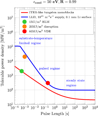
Figure 1. The maximum tolerable power density has been determined for a LL divertor target (blue) with thermal properties equal to the ITER-like monoblocks (red). This target has a Li supply rate  of 1025 m−2 s−1, and a 0.1 mm top layer.
  and R are taken 50 eV and 0.99, respectively. The blue curve shows three characteristic regimes: the steady state regime, the pulsed regime, and the substrate-temperature limited regime. The behavior of the former two regimes is detailed in figures 2 and 3. The −1 slope of the pulsed regime is due to the fact that the thickness of the Li layer on the PFS corresponds to a fixed energy density which can be dissipated.
Download figure:
Standard image High-resolution imageThe blue curve in figure 1 is calculated for  1025 m−2 s−1, which corresponds to a Li flux that could be supplied purely passively via only capillary forces (as for the design proposed in [25]). The influence of
  , surface layer thickness,
  , t, and R is visualized in figures 2 and 3. Additionally, figure 2 shows the impact of doubling the thermal conductance of the system.
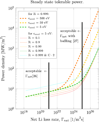
Figure 2. The steady state tolerable power density as function of  . A conductive regime and Li dissipation dominated regime can be observed below and above ∼ 20 MW m−2 s−1, respectively. Illustrated is also the influence of
  (dashed), which mainly impacts the regime where dissipation via Li is dominant, and R (solid), which impacts surface temperature to reach a given
  and thus the conductive dissipation. The cyan line illustrates the effect of increasing the target conductance with a factor of 2. Also note that fuel dilution in the core plasma limits the allowable
  , illustrated by the black lines.
Download figure:
Standard image High-resolution image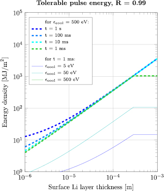
Figure 3. The energy density that can be dissipated in the pulsed regime depends linearly on the PFS LL layer thickness. For layers thinner than 10 micron conductive dissipation becomes important and dependence on pulse length t increases. For high layer thickness the substrate temperature limit is reached before all Li can be evaporated (above 200 micron for R = 0.99 as presented here).
Download figure:
Standard image High-resolution image
4. Discussion
In steady state (figure 2) two 'operating modes' can be distinguished clearly: a conductive and a Li dominated mode. At respectively low load, heat is dissipated mainly via conduction. In this mode, the tolerable power density can be even lower than for the monoblocks, as low surface temperature is required to maintain low net loss rates. Loads below ∼4 MW m−2 (depending on target conductance) are not possible because then the surface temperature becomes so low that retention becomes problematic. Increasing the effective thermal conductance of the system linearly increases the tolerable load as illustrated by the cyan curve.
In the Li dominated mode orders higher power density can be absorbed, though, this mode requires net Li loss rates at least above 1023 m−2 s−1. Note that in this mode, in order to handle the increased power density, only a slight increase in the surface temperature is required due to the strong dependence of evaporation on temperature. This results in a temperature locking phenomenon as recently observed for liquid tin [12], and earlier on carbon fiber composite [28]. Modeling in [15] also clearly demonstrated that the cause is the strong temperature dependence of the evaporation rate. For Li the locking temperature is expected to be in the range of 800 °C–1000 °C.
The compatibility of these conditions with a high-performance fusion core needs to be assessed. It is estimated in [26] that  should not exceed ∼1021 m−2 s−1 to avoid fuel dilution in the core (indicated by the left black line in figure 2). The acceptable flux density could be increased via strong baffling. For example, placing the target inside a vapor box as presented in [27] (despite being designed with a different working principle in mind) can reduce the Li outflow by four orders of magnitude, increasing the acceptable net loss rate up to ∼1025 m−2 s−1.
In the pulsed regime dissipation by the Li is dominant for layer thicknesses above ∼10 micron, as indicated by the low dependence on pulse duration in figure 3. Consequently, the tolerable pulse energy density varies linearly with  , until the layer reaches critical thickness where the temperature required to evaporate all Li during the pulse exceeds the substrate melting point. This point is clearly seen in figure 3 at a layer thickness around 300 micron, where the curves representing 1 ms pulses suddenly stop increasing. By increasing R from 0.99 (used in figure 3) to 0.999 the critical thickness will be reduced from ∼300 micron to ∼30 micron. This is simply because higher temperature is required to remove a given amount of Li when redeposition becomes stronger.
Now figure 3 can be used to find what layer thickness (horizontal axis) is needed to withstand arbitrary energy density (y-axis). Most notable is that 1 ms disruptions of 20 MJ m−2, where it is expected that  eV, can already be withstood with layer thickness of 50 micron. Though not drawn in figure 3 the model also shows that for 200 ms vertical displacement events (VDE) up to 60 MJ m−2 a 50 micron layer is also sufficient if
  eV. ELMs of 0.5 ms require even smaller layer thickness of ∼2 micron when
  eV, corresponding to ∼1023 m−2 Li particles being released into the plasma per ELM. Thus, there may still be concerns regarding the compatibility of high Li loss rates during ELMs with the core plasma. This is not problematic for VDEs and disruptions as the plasma is lost in these cases.
Lastly, the model considers a realistic range of  , and surface layer thickness, and therefore provides us with a limit to the power handing capabilities of a LL divertor target. Nevertheless, to obtain a more accurate estimate of power dissipation via Li further edge transport studies would be required. To also gain more insight into the acceptable Li loss rate, coupling edge and core transport modeling would even be required (for example continuing along the line of [29]).
5. Conclusion
Firstly, the formulated model can predict temperatures in LL divertor targets, making it a powerful engineering tool for the design of these components. Additionally, an important observation is the temperature locking effect, reducing both the peak temperature during steady state (to around 800 °C–1000 °C) and during pulses. Namely, this will reduce thermal stresses, and therefore relaxes the high requirements to the strength of divertor substrate materials compared to conventional designs.
Secondly, the steady state tolerable load can be spectacularly increased compared to W monoblocks, but always at the cost of high LL loss rate. To match the monoblock performance loss rates are required of ∼1025 m−2 s−1 for  eV when R = 0.999. Though, the loss rate for this case can be reduced ∼3 orders of magnitude by increasing the thermal conductance of the system, and ∼4 orders of magnitude via baffling as proposed in the vapor box concept [16]. This puts the net loss rate in the acceptable range. Nevertheless, the compatibility of specific loss rates with a high-performance fusion core should be further investigated.
Finally, regarding pulsed loads: Li layers with a thickness of 50 micron are already sufficient to withstand ELMs, disruptions, and VDEs. In the case of ELMs this may still lead to core plasma compatibility issues, but this is certainly not the case for the disruptions and VDEs as these are off-normal events, and thus the plasma is lost regardless. The ability to withstand these off-normal events is a significant and important improvement in robustness over traditional solid divertors.
Acknowledgments
This work has been carried out within the framework of the EUROfusion Consortium and has received funding from the Euratom research and training programme 2014–2018 under grant agreement No. 633053. The views and opinions expressed herein do not necessarily reflect those of the European Commission.