


Abstract
The ASDEX Upgrade (AUG) programme is directed towards physics input to critical elements of the ITER design and the preparation of ITER operation, as well as addressing physics issues for a future DEMO design. Since 2015, AUG is equipped with a new pair of 3-strap ICRF antennas, which were designed for a reduction of tungsten release during ICRF operation. As predicted, a factor two reduction on the ICRF-induced W plasma content could be achieved by the reduction of the sheath voltage at the antenna limiters via the compensation of the image currents of the central and side straps in the antenna frame. There are two main operational scenario lines in AUG. Experiments with low collisionality, which comprise current drive, ELM mitigation/suppression and fast ion physics, are mainly done with freshly boronized walls to reduce the tungsten influx at these high edge temperature conditions. Full ELM suppression and non-inductive operation up to a plasma current of  MA could be obtained at low plasma density. Plasma exhaust is studied under conditions of high neutral divertor pressure and separatrix electron density, where a fresh boronization is not required. Substantial progress could be achieved for the understanding of the confinement degradation by strong D puffing and the improvement with nitrogen or carbon seeding. Inward/outward shifts of the electron density profile relative to the temperature profile effect the edge stability via the pressure profile changes and lead to improved/decreased pedestal performance. Seeding and D gas puffing are found to effect the core fueling via changes in a region of high density on the high field side (HFSHD).
The integration of all above mentioned operational scenarios will be feasible and naturally obtained in a large device where the edge is more opaque for neutrals and higher plasma temperatures provide a lower collisionality. The combination of exhaust control with pellet fueling has been successfully demonstrated. High divertor enrichment values of nitrogen  have been obtained during pellet injection, which is a prerequisite for the simultaneous achievement of good core plasma purity and high divertor radiation levels. Impurity accumulation observed in the all-metal AUG device caused by the strong neoclassical inward transport of tungsten in the pedestal is expected to be relieved by the higher neoclassical temperature screening in larger devices.
Export citation and abstract BibTeX RIS

Content from this work may be used under the terms of the Creative Commons Attribution 3.0 licence. Any further distribution of this work must maintain attribution to the author(s) and the title of the work, journal citation and DOI.
This article was updated on 26 August 2021 to correct the copyright line.
1. Introduction and technical boundary conditions
Due to its thermo-mechanical properties and the low sputtering rates for divertor conditions, tungsten (W) is currently regarded as the most viable choice for a plasma facing material in a fusion reactor. ASDEX Upgrade is operated with tungsten coated plasma facing components (PFCs) since its 2007 experimental campaign [1], a part of the heat shield is covered by magnetic P92 and Eurofer steel tiles for testing of DEMO PFCs from 2013 onwards [2]. A major effect of the tungsten coated PFCs is the sputtering of tungsten atoms, which may enter the pedestal region and lead to radiative losses in the core plasma. Under certain conditions, accumulation of W ions near the plasma center occurs which can lead to confinement degradation, a H-L transition or the development of strong MHD modes. Prevention of W accumulation requires central (wave) heating to foster a high central W transport level which counteracts the neoclassical inward pinch and/or a sufficiently high gas puff level. The latter acts via SOL cooling (reduction of sputtered W flux) and W flushing out of the pedestal by ELMs. Scenarios which are most hampered by these measures are those requiring a low plasma density, like those with a high current drive fraction or the requirement of low pedestal collisionality, as needed for ELM mitigation or suppression by magnetic perturbations (MP). In addition to the high W influx, peaked density profiles intensify the neoclassical tungsten inward pinch [3]. For AUG operation, this means that respective experiments have to be performed with relatively fresh boronization. Boronizations cover up limiters and other PFC surfaces for a short time (about one operational day), and reduce the W sputtering by the reduction of other impurities content (a few weeks), which finally reduces the release of W to the plasma [4]. This allows a reduction of the D puff level, which is particularly important for current drive, fast ion and ELM mitigations studies. As will be shown in this paper, integration of the above mentioned scenarios in a larger device appears feasible, and in particular problems caused by the strong inward transport of W in the pedestal are expected to be relieved.
2. Tungsten related hardware upgrades
2.1. New 3-strap ICRF antennas
Enhanced sputtering of tungsten (W) has been a caveat for ICRF operation with all-W coated plasma facing components due to corresponding high radiative losses [6]. This problem has been ameliorated by the coating of antenna limiters with boron, however, a sustainable solution had to be found for a possible reactor application due to the too high erosion rates of low-Z elements. The enhanced release of W from limiters during ICRF operation is at least partly caused by ion acceleration in the sheath electric field which is produced by image currents in the antenna housing. An optimised 3-strap antenna was designed which is able to minimize the image currents by compensation of the fields generated by the central strap with those by the side straps [5]. Figure 1 shows the tungsten concentration in the plasma during operation of the new 3-strap antennas with W-coated limiters in comparison to the 2-strap antennas with boron coated limiters, as well as a comparison of 2-strap antenna pairs with W-coated and B-coated limiters prior to the installatiom of the 3-strap antennas. The new 3-strap antenna pair with W-coated limiters performs comparably well as the old 2-strap antenna with B-coated limiters. The positive effect of central ICRF heating with the new 3-strap antennas for W accumulation avoidance can be seen from the central W concentration rise after ICRF switch-off at t = 6.5 s in the middle figure. A similar rise of the central W concentration after ICRF switch-off takes place also in #27559 (not shown in figure 1), here the NBI power has reduced from 7.5 to 5 MW simultaneously. Additional improvement of ICRF operation is achieved from local gas puffing in the vicinity of the antennas, which has also been found to improve the power coupling [7].

Figure 1. Comparison of plasma W content during ICRF heating between B- and W-coated 2-strap antennas (left) and the B-coated 2-strap with a W-coated 3-strap antenna (middle). Both discharges have 7.5 MW NBI power in addition to the ICRF. Also shown is a sketch of the new 3-strap antenna, indicating the cancellation of the image currents at the antenna frame limiters [5].
Download figure:
Standard image High-resolution image2.2. Divertor III with massive tungsten tiles
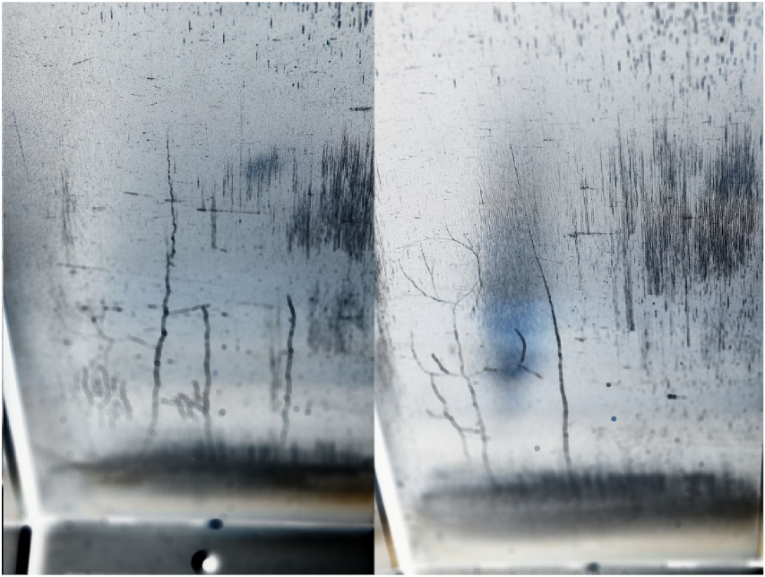
Since 2014, AUG is equipped with the outer divertor III consisting of massive tungsten tiles in the power wetted regions [8]. During plasma operation, different types of cracks developed in all of the 128 tiles, as shown in figure 2. Such cracks were not observed in previous heat flux tests in the GLADIS device [8]. In addition to the temporally smooth thermo-elastic stresses, forces occuring during disruptions and ELM loads are made responsible for the crack formation. An underlying reason for the crack formation is the low operating temperature of the AUG divertor, which results in a high brittleness of the W tiles. This behaviour may be reminiscent of a future DEMO divertor which is operated at higher temperature, but exhibits an elevated ductile-brittle transition temperature due to degradation by neutrons. The crack formation, despite partially going through the full tile depth, did neither cause a partial tile loss nor forced a machine opening. Since this can not be excluded for subsequent campaigns, counter measures are taken during the current machine vent. FEM calculations suggest that a vertical cut/castellation of the tiles will ameliorate the formation of cracks and their propagation in poloidal direction. Therefore, the inner 6 out of 8 tiles of a divertor segment are being castellated. For the remaining 2 side tiles, a different solution is applied: a much more ductile W-Ni/Fe material [9] will be used, which showed no cracks during tests under high power divertor conditions with the manipulator DIM-II. The segregation of Ni and Fe at high surface temperatures around 1500 C is not expected to hamper AUG operation.

Figure 2. Foto of 2 strike point tiles of the massive W divertor III after 2 campaigns. Each tile has a width of 74 mm, a height of 213 mm and a thickness of 15 mm.
Download figure:
Standard image High-resolution image3. Scenario development
3.1. Non-inductive operation
Studies for non-inductive operation are done on AUG usually in the first week after a boronization, since a low core density and high temperatures are a prerequisite for high neutral beam current drive (NBCD) and electron cyclotron current drive (ECCD) efficiencies. Discharges aiming at non-inductive operation usually work at high normalized pressure,  , use an optimized shape and low gas puff values [10]. The safety factor q is aimed to remain above 1.5 to avoid sawteeth and NTMs with helicities up to a m/n = 3/2. Figure 3 shows time traces of a discharge where about full non-inductive operation could be achieved with NBCD and ECCD [11] at a plasma current of
  MA and a line-averaged density of
  m−3. About 35
 of the plasma current are driven by NBCD. Pre-emptive ECCD is used to obtain an optimized current profile. The equilibrium has been reconstructed with a novel code based on integrated data analysis [12] using all available data including Faraday rotation polarimetry and motional Stark effect (MSE) polarimetry. The MSE diagnostic was found to be affected by interference from polarized background light, resulting from (polarizing) reflections by the tungsten wall. Corresponding systematic errors of the MSE angles are taken into account in the analysis and limit the accuracy of the equilibrium reconstruction to
  . The self-generated bootstrap current provided about 50
 of the total current. Due to the high β values, this scenario is situated close to the no-wall MHD limit. The central tungsten concentration is about
  , resulting in about 0.7 MW tungsten radiative losses, which is small compared to the heating power of 15 MW. Dedicated discharges with off-axis NBCD were performed to check the consistency of FIDA and MSE measurements with TRANSP simulations, using improved analyses [13]. For MHD quiescent conditions, FIDA signals during on-axis NBCD are well reproduced by TRANSP with low levels of anomalous fast ion transport. In the off-axis case, moderate discrepancies between simulated and measured FIDA radial profiles remain [14].

Figure 3. Time traces and profiles of non-inductive AUG discharge #32305. NBI heating power is 10.5 MW, ECRH 2.7 MW, plasma current  MA,
MA,  T,
T,  .
.
Download figure:
Standard image High-resolution image3.2. ELM mitigation and suppression
Full suppression of ELMs using resonant magnetic perturbations could be obtained in collaboration with DIII-D, where a triangularity dependence of the ELM suppression threshold had been detected in AUG similarity studies [15]. Time traces of a corresponding discharge are shown in figure 4. The ELM suppression is accompanied by a strong density pump-out, while the energy confinement is moderately degraded. With the vanishing ELM flushing during ELM suppression, accumulation of tungsten in the core plasma has been regarded as possible issue. However, and in contrast to classical ELM-free periods in between type-I ELMs, the tungsten concentration inside the pedestal and in the plasma center remains about 10−4 in ELM suppressed AUG discharges, causing moderate radiative losses (≈0.4 MW) due to the low plasma density. Tungsten influx pulses brought into the edge deliberately by ICRF with detuned phasing do not exhibit prolonged decay times in the central W radiation. This suggests a particle transport mechanism which at least partly compensates the lack of ELM losses. ELM mitigation by magnetic perturbation in AUG generally correlates with a reduction of the pedestal density (density pumpout), and hence a reduction of the pedestal pressure and the global energy confinement. The strength of the density reduction depends on the degree of coupling of the external perturbation field to ideal modes that are amplified by the edge pressure gradient and edge current density [16] [17]. Figure 5 shows this correlation for a wide range of experimental conditions at low pedestal collisionality, including phase scans of the magnetic perturbation [18]. If, e.g. the density pumpout is recovered by pellet injection [19], the ELM size also increases. The pedestal density cannot be directly used for extrapolation to a larger device. Since the collisionality also plays a role in ELM mitigation by RMPs, further work is required for the development of an ELM loss scaling in dimensionless parameters. Recovery of energy confinement may be at least partly achieved by parameter optimization of the MP spectrum and fueling [20]. It should be noted that the peak ELM heat flux at the target, which constitutes the main engineering constraint on the ELM size, was found for type-I ELMs to scale linearly with the pedestal pressure for all experimental conditions, with a factor 3 variation remaining in heat flux at a given pressure [21, 22].

Figure 4. Time traces of a discharge with full ELM suppression by magnetic perturbations with a toroidal mode number n = 2, q95 = −3.7. W blips are introduced at 3.5 and 4.5 s by dedicated ICRF with detuned phasing.
Download figure:
Standard image High-resolution image
Figure 5. Fractional ELM pedestal energy loss versus pedestal density for low collisionality conditions  [18]. Reproduced from [18]. © IOP Publishing Ltd. All rights reserved.
Download figure:
Standard image High-resolution image4. Pedestal stability and confinement
The pedestal is the key area determining the total plasma stored energy as well as the impurity content of H-mode plasmas in AUG. Considerable changes in energy confinement, ELM behaviour and L-H power threshold have been observed during the change from C to W walls.
4.1. L-H transition and pedestal radial electric field
The reduction of the L-H power threshold by about 25 during the change from carbon to tungsten PFCs has been explained by steeper edge density profiles at the same input power, and hence a steeper neoclassical Er
well with W walls [23]. The deepening Er
well eventually induces the transition to H-mode via its associated radially sheared flow [24]. Modelling with the EMC3-Eirene code revealed the higher energy reflection coefficients of W walls compared to carbon as the underlying reason for steeper density profiles for relatively low edge density conditions [25]. Measurements of the edge radial electric field [26], in particular during the L-H transition, have been continued with improved temporal resolution. Up to the diagnostic time resolution of 100 μs, the radial electric field in the pedestal appears to be neoclassical, i.e. the main ions are almost at rest since their
during the change from carbon to tungsten PFCs has been explained by steeper edge density profiles at the same input power, and hence a steeper neoclassical Er
well with W walls [23]. The deepening Er
well eventually induces the transition to H-mode via its associated radially sheared flow [24]. Modelling with the EMC3-Eirene code revealed the higher energy reflection coefficients of W walls compared to carbon as the underlying reason for steeper density profiles for relatively low edge density conditions [25]. Measurements of the edge radial electric field [26], in particular during the L-H transition, have been continued with improved temporal resolution. Up to the diagnostic time resolution of 100 μs, the radial electric field in the pedestal appears to be neoclassical, i.e. the main ions are almost at rest since their  rotation cancels the diamagnetic drift [27]. In this picture the ion pressure gradient is the dominant parameter for the L-H transition, and hence the ion heat flux at the plasma edge [28].
Limit cycle oscillations in the I-phase preceding the L-H transition exhibit large turbulence amplitudes which are always accompanied by weaker gradients and lower Er
. A correlation analysis revealed that, within the experimental resolution, the evolution of all three quantities is simultaneous. A shown in figure 6, the  rotation cancels the ion diamagnetic drift also during the oscillations. This result suggests no large contribution from zonal flows to the radial electric field and to the L-H transition mechanism at least on the resolved timescale. The limit cyce oscillations exhibit an ELM-like behaviour: Particles and energy are expelled during each turbulent phase [29].

Figure 6. Lissajous diagrams following the temporal evolution between  and
and  at three different radial positions during limit cycle oscillations [27]. The
  flow is measured by fast charge exchange recombination spectroscopy (CXRS). The length of the time interval shown is 1.8 ms. Reproduced courtesy of IAEA. Figure from [27]. Copyright 2017 IAEA.
Download figure:
Standard image High-resolution image
Bt scans during the L-H transition confirmed that the ion sheared flow  and not Er
is the important player, which explains the Bt dependence of the power threshold. Transport studies on the isotope effect of the L-H transition revealed an about a factor of two higher ion heat flux for hydrogen compared to deuterium at the transition [28]. Since the L-H transition occurs at about the same edge plasma parameters in H and D, and hence the same Er
, the higher power threshold is mainly due to the higher ion heat transport in L-mode in this gas.
and not Er
is the important player, which explains the Bt dependence of the power threshold. Transport studies on the isotope effect of the L-H transition revealed an about a factor of two higher ion heat flux for hydrogen compared to deuterium at the transition [28]. Since the L-H transition occurs at about the same edge plasma parameters in H and D, and hence the same Er
, the higher power threshold is mainly due to the higher ion heat transport in L-mode in this gas.
4.2. Energy confinement variation with impurity seeding
After transition to full metallic PFC devices, a reduction of energy confinement has been observed under certain experimental conditions both in ASDEX Upgrade and in JET [30] [31]. The reduction has been attributed to the absence of a low-Z edge radiating species and a shift to higher core electron densities. Good confinement could be recovered—for a broad experimental parameter range in AUG and certain scenarios in JET—by nitrogen or carbon (CD4) seeding. Different potential mechanisms capable of causing a confinement improvement during low-Z impurity seeding have been discussed in the past [32], but none of them appeared sufficiently strong to solely explain the up to about 30 increase in stored energy. Recently, the inward shift of the pedestal density profile was identified as the underlying reason for a higher pedestal stability during nitrogen seeding in AUG [33]: The reduction of the high field side high density (HFSD) pattern due to the enhanced SOL radiation during nitrogen seeding [34, 35] effects the fueling in the X-point region in a way that leads to an inward shift of the density profile and a reduction of the separatrix density. It cannot be fully ruled out that a possible anomalous inward particle pinch in the pedestal region changes with impurity seeding and contributes to the inward shift of the density profile. A dedicated analysis of the density build-up in the pedestal after the L-H transition revealed low pinch values around −0.5 m s−1, however a range between 0 and −5 m s−1 could not be excluded due to the uncertainties involved [36].
Since the temperature profile is anchored at the separatrix, the inward shift of the density profile leads to an inward shift of the high pressure gradient region. As a consequence, the edge high shear region, which is favourable for the stability, is moved inward as well. Figure 7 shows experimental pedestal pressure values as a function of separatrix density for different gas puff and seeding conditions. In addition, the maximum pedestal top pressure for a predictive stability analysis is shown for arbitrary radial shifts of the density profile [33]. Beta and Zeff have been kept fixed in this case, and variations of the temperature and density profile shapes are used to obtain realistic pressure profiles for this artificial scan. Overall, the experimental trend for the separatrix density dependence of the pedestal top pressure is well matched. Individual experimental pedestal top values are also well matched by the stability calculations. It has to be kept in mind, that for experimental seeding scans, an interplay of different mechanisms affects the pedestal stability beyond the effect of the density profile shift, namely the positive effect of an increased β / Shafranov shift and the effect of Zeff reducing the bootstrap current [32, 37].

Figure 7. Pedestal pressure versus separatrix density for N seeded (full symbols) and non-seeded discharges with different gas puff levels.  MA,
MA,  –14 MW. The right figure shows a model study of stability analyses for conditions of different radial shifts of the density profile.
Download figure:
Standard image High-resolution image4.3. Mode activity correlating with pedestal profile clamping
Kinetic ballooning modes [39] are theoretically considered for the clamping of the pedestal pressure profile, which is observed in ASDEX Upgrade over several milliseconds before an ELM occurs. Figure 8 shows ELM-synchronized magnetic fluctations associated to the clamping of the pedestal pressure [38]. A fit to the estimated  rotation velocity in the steep gradient region for different discharges yields a toroidal mode number around n = −11, which is in line with results from mode number analysis using 5 toroidally separated ballooning coils in the outer midplane for selected cases. The minus sign refers to counter-current (electron diamagnetic) rotation. The presence of magnetic fluctuations on the high field side does not correspond to a ballooned mode structure, which is expected for an instability that is driven by the pressure gradient on the LFS. The modes are not regarded to be ELM-precursor modes, since they may remain under quasi-stationary conditions for several milliseconds, and their occurrence / non-occurrence may lead to the existence of two different main ELM frequencies in a single discharge phase [40].

Figure 8. Magnetic fluctuations  related to the clamping of the pedestal pressure in the later part of an ELM cycle with frequencies around 200 kHz are observed both on the high-field and low-field sides (see (a)). The spectrogram shown has been ELM sychronized. A toroidal mode number n of approximately −11 is obtained from a linear fit to the
  background flow assumed as the compensation of the ion diamagnetic drift as calculated from the pressure gradient for various discharge conditions [38]. Reproduced from [38]. © IOP Publishing Ltd. All rights reserved.
Download figure:
Standard image High-resolution image5. Power exhaust
5.1. High power detachment with Ar and X-point radiating zone
Power exhaust studies were continued aiming at maintaining detached conditions at higher heating powers. Argon is a suitable radiative cooling species for the outer core and pedestal region. Experiments have been conducted aiming at the achievement of detachment with Ar as only seed impurity at high power, complementing previous studies with nitrogen seeding for detachment by divertor radiation [41]. Figure 9 shows time traces of a high power discharge with constant Ar seeding. Different discharge states are obtained by stepping down 3 NBI sources resulting in a variation of the total heating power from 26 to 18 MW. After the 2nd power step, at t = 4.35 s, a radiating zone develops at and inside the separatrix slightly above the X-point, resembling the transition to pronounced detachment during nitrogen seeding [41]. The radiation inside the X-point is connected to divertor detachment, a substantial increase of line-averaged and pedestal density and a reduction of ELM size from about 9% to 5 of the total stored energy, and lower W divertor sputtering and W core content. Later on, at t = 5.05 s, an increase of ELM frequency and further reduction of ELM size to about 1.5
 of WMHD occurs. Bolometer tomography shows a reduction of the HFSHD radiation with the occurence of the X-point radiator, and also a reduction of the outer divertor radiation. The Langmuir probe closest to the separatrix, situated 4 cm in the SOL along the target, records a reduction of heat flux and electron pressure by an order of magnitude between t = 4.1 and 4.7 s. Energy confinement is reduced by the presence of a 3/2 neoclassical tearing mode throughout the time interval shown, H98 appears to decrease during the X-point radiation formation by 15
 , but 10
 reduction are just caused by the density rise and the
  dependence of H98. The pedestal electron pressure stays constant over this transition, a moderate drop is just observed during the transition to very small ELMs. The X-point radiating regime with pronounced detachment may become an interesting ITER or DEMO scenario. Although the detachment is more pronounced than the partial detachment required by ITER PFCs, the reduced ELM size, increased density and reduced W sputtering are assets. Once developed, the X-point radiating regime appears stable and suited for active control, e.g. by bolometry line integrals.

Figure 9. Time traces of a Ar seeded high power discharge with heating power variation. Bolometer tomography shows the radiation distribution in divertor and X-point region. The Ar puff rate is kept constant at 2 1021 el s−1 during the time interval shown. The main chamber radiation signal decreases with the formation of the X-point radiating zone, its sightlines lie above the X-point [42].
Download figure:
Standard image High-resolution image5.2. Divertor impurity enrichment
An important issue in scenarios with low-Z divertor seeding (N, Ne) is the dilution of the main plasma by the seeded species, which will be tightly limited in reactor burning scenarios. The divertor enrichment E is the experimental parameter which relates the divertor concentration of an impurity to the concentration in the core. E is calculated as

 are the valve fluxes measured in electrons s−1, nZ
is the outer core impurity density, typically derived at
are the valve fluxes measured in electrons s−1, nZ
is the outer core impurity density, typically derived at  to avoid central peaking effects and minimise uncertainties in CXRS measurements. ne
is the electron density at the same location. (The charge Z enters since the valve flux is measured in electrons s−1, Z = 7 for N and Z = 10 for Ne). Valve fluxes are used because no appropriate direct measurement of the divertor impurity density is available. The ratio of the valve fluxes, assuming a balance of puffing and pumping, corresponds to the particle fluxes in the divertor. Since high power exhaust scenarios require concentrations of several
to avoid central peaking effects and minimise uncertainties in CXRS measurements. ne
is the electron density at the same location. (The charge Z enters since the valve flux is measured in electrons s−1, Z = 7 for N and Z = 10 for Ne). Valve fluxes are used because no appropriate direct measurement of the divertor impurity density is available. The ratio of the valve fluxes, assuming a balance of puffing and pumping, corresponds to the particle fluxes in the divertor. Since high power exhaust scenarios require concentrations of several  of the seed impurity in the divertor [43], enrichment values around 3–5 are at least required to keep core concentrations cz
below 1–2
of the seed impurity in the divertor [43], enrichment values around 3–5 are at least required to keep core concentrations cz
below 1–2 . Figure 10 shows enrichment values obtained for N and Ne under different H-mode conditions. There is a trend for increasing E with ELM frequency, but obviously fELM is not the only important parameter. The lower enrichment of Ne in comparison to N is supposed to be partly caused by the higher ELM frequency during N seeding. Other effects will be the longer ionisation mean free path of Ne [35], reducing its confinement in the divertor, and a slightly higher neoclassical inward drift of Ne in the pedestal. Pellets help to increase E (see also section 6), trivially by the D fueling, but maybe also by increased impurity outflux in the pedestal. The overall lower divertor enrichment of Ne compared to N contributes to the fact that N is the more successful divertor radiating species in AUG.

Figure 10. Divertor enrichment of N and Ne as a function of ELM frequency for divertor radiative cooling experiments.
Download figure:
Standard image High-resolution image6. Scenario integration and extrapolation
The combination of low pedestal collisionality (required for ELM mitigation or suppression) and low divertor temperatures will only be possible in a large device. The larger size results naturally in a higher pedestal temperature, and makes the density in the SOL and in the pedestal region more independent due to a more opaque SOL. Since the edge temperature profile will be largely determined by the power flux, optimization of the edge pressure profile will rely mainly on the density profile. Possible actuators here are the fuelling obtained from the divertor / X-point region and the particle source provided by pellet injection. Figure 11 shows time traces of a discharge with a combination of line-averaged density control by pellet injection and divertor temperature / heat flux control by nitrogen seeding. Both controllers work combined without interference problems. Also shown is the nitrogen divertor enrichment. The enrichment E is understood as a smoothed version of the time trace shown, since averaging effects of wall particle uptake and release [44] and the time constant of the divertor have to be taken into account. Figure 12 shows pedestal profiles and a stability analysis of #33237 for the 3 phases without N and pellets, with N seeding only and combined pellet fueling and N seeding. At t = 1.8 s, the high gas puffing rate causes low energy confinement, H98 = 0.8. This is attributed to an outward shifted density profile, in connection with a strong HFSHD region. The resulting outward shifted pressure profile exhibits a steep gradient, but only over a narrow width resulting in a reduced pedestal top pressure. The injection of N reduces the HFSHD, leading to an inward shift of the density profile, and in combination with the increased beta, to improved stability. The pellet injection again leads to an outward shift of the density profile, reducing again the pedestal performance. The effect of the outward shift is partly compensated by the higher density, which reduces the edge bootrap current and thus the peeling drive. After injection of the last pellet, fast central accumulation of W occurs. This is caused by the transient peaking of the density profile after switching off the edge source. A slow ramp-down of the pellet rate compared to the central particle confinement time would be required for avoidance of this W accumulation, which is currently not feasible due to the limited amount of pellets for one discharge. A part of the experimental difficulties observed in the fully metallic AUG is caused by the strong neoclassical inward transport of tungsten and heavy seed impurities towards the pedestal top, which required a sufficiently high ELM frequency for the avoidance of an excessive core impurity density. For larger machines with higher pedestal temperatures, the situation is expected to be considerably relieved [45].

Figure 11. Time traces of a discharge with combined density control by pellets and target heat flux control by N seeding. Also shown in the lower right box is the nitrogen divertor enrichment, which increases during pellet injection. The H98 factor is only shown till the start of the pellet injection, but the only slightly decreasing stored energy at constant heating power suggests only a very mild energy confinement degradation. The D valve flux is reduced to keep the total D divertor flux constant during pellet injection.
Download figure:
Standard image High-resolution image
Figure 12. Pedestal profiles of temperature, density and total pressure for 3 timepoints of the discharge shown in figure 11, and stability analysis of these points. Data points are from Thomson scattering, ECE emission and Li beam data. ECE measurements are mainly in cut-off during pellet injection.
Download figure:
Standard image High-resolution imageFigure 13 shows the result of neoclassical transport calculations for an artificial machine size scan with a realistic variation of pedestal temperature, plasma current and toroidal field at constant safety factor q95. The tungsten pedestal top to separatrix density ratio, fnW, is found to decrease substantially with size, ranging from a tungsten separatrix-to-pedestal density rise by almost a factor 10 for AUG conditions to a pedestal depletion for machines with major radius  m. The effect is mainly driven by the higher pedestal temperature, which increases the neoclassical temperature screening. The pedestal width has been, somewhat arbitrarily, increased with machine size, however, this has only a minor influence on the derived peaking factor, which is the integral of the drift parameter v/D and dominated by
  and
and  . With larger size, the drift parameter attains more positive, i.e. outward directed, values in the outer part of the pedestal. The pedestal W accumulation predicted for AUG conditions is reduced by ELM flushing of tungsten under typical experimental conditions. Accordingly, the depletion predicted for large machines may be reduced by ELM inward flushing [45]. In general, the shown variation of neoclassical effects with pedestal parameters suggests much more favourable conditions regarding W accumulation avoidance in large devices.

Figure 13. Evaluation of the neoclassical tungsten pedestal-separatrix density peaking factor,  for an artificial machine size scan. fnW decreases with increasing Tped.
Download figure:
Standard image High-resolution image
7. Conclusions and outlook
Individual scenarios have been developed in ASDEX Upgrade which favourably extrapolate to large devices like ITER or DEMO. Full integration of these elements: non-inductive operation, power exhaust, ELM mitigation/suppression cannot be obtained in a device of AUG size since the high edge density required for power exhaust is not compatible to a low pedestal top collisionality, which is supposed to be required for ELM suppression. The higher degree of opacity in a larger machine with a geometrically broader SOL should allow the de-coupling of the pedestal top and SOL densities. Future studies are required to pin down the governing plasma parameters for the accessibility of ELM suppression by magnetic perturbations, since AUG data point towards a role of the absolute density value in contrast to mere collisionality. Restrictions of the AUG operational space caused by the presence of tungsten walls are expected to be relaxed by less inward-directed neoclassical impurity transport due to the stronger pedestal temperature gradient screening. In addition, the role of neoclassical W transport in the core is expected to be much smaller in a reactor plasma compared to current devices, resulting in less charge-dependent inward directed convective transport [46]. Another positive element will come from improved ICRF antennas, further pursuing the development path of the new 3-strap antennas in AUG, which could significantly reduce the release of tungsten ions.
A qualitative picture about the role of gas puffing on power exhaust and confinement is developing. While a high neutral pressure in the divertor is required to achieve detachment at high  , a high separatrix density may lead to an unfavourable location of the density profile. Here, a more opaque SOL in a large device may be helpful, provided pellet fueling can be obtained deep enough in the pedestal region to provide a source profile being compatible to the desired density gradient location. Ideally, the pellet fueling should be tailored to optimize the edge pressure profile regarding stability and ELM size.
Very high values of the divertor enrichment  for nitrogen have been measured during pellet fueling, allowing the combination of a high divertor radiation with low core plasma dilution. For standard conditions, neon shows a reduced enrichment compared to nitrogen. This behaviour is attributed to a lower ELM frequency in Ne seeded discharges and a longer ionization mean free path for Ne compared to N.
Acknowledgments
This work has been carried out within the framework of the EUROfusion Consortium and has received funding from the Euratom research and training programme 2014-2018 under grant agreement number 633053. The views and opinions expressed herein do not necessarily reflect those of the European Commission.
Appendix. The ASDEX Upgrade Team
D. Aguiam2, L. Aho-Mantila3, C. Angioni1, N. Arden1, R. Arredondo Parra1, O. Asunta4, M. de Baar5, M. Balden1, K. Behler1, A. Bergmann1, J. Bernardo2, M. Bernert1, M. Beurskens6, A. Biancalani1, R. Bilato1, G. Birkenmeier1,7, V. Bobkov1, A. Bock1, A. Bogomolov5, T. Bolzonella35, B. Böswirth1, C. Bottereau9, A. Bottino1, H. van den Brand5, S. Brezinsek10, D. Brida1,7, F. Brochard11, C. Bruhn1,7, J. Buchanan6, A. Buhler1, A. Burckhart1, D. Cambon-Silva1, Y. Camenen9, P. Carvalho2, G. Carrasco6, C. Cazzaniga8, M. Carr6, D. Carralero1, L. Casali1, C. Castaldo12, M. Cavedon1,7, C. Challis6, A. Chankin1, I. Chapman6, F. Clairet7, I. Classen5, S. Coda13, R. Coelho2, J.W. Coenen10, L. Colas9, G. Conway1, S. Costea14, D.P. Coster1, G. Croci12, G. Cseh15, A. Czarnecka16, O. D'Arcangelo12, C. Day17, R. Delogu12, P. de Marné1, S. Denk1,7, P. Denner10, M. Dibon1, R. D'Inca1, A. Di Siena1, D. Douai9, A. Drenik1, R. Drube1, M. Dunne1, B.P. Duval13, R. Dux1, T. Eich1, S. Elgeti1, K. Engelhardt1, B. Erdös15, I. Erofeev1, B. Esposito8, E. Fable1, M. Faitsch1, U. Fantz1, H. Faugel1, F. Felici18, S. Fietz1, A. Figueredo5, R. Fischer1, O. Ford1, L. Frassinetti19, S. Freethy1.20, M. Fröschle1, G. Fuchert1, J.C. Fuchs1, H. Fünfgelder1, K. Galazka16, J. Galdon-Quiroga21, A. Gallo9, Y. Gao10, S. Garavaglia12, M. Garcia-Muñoz21, B. Geiger1, C. Cianfarani12, L. Giannone1, E. Giovannozzi9, C. Gleason-González17, S. Glöggler1,7, M. Gobbin12, T. Görler1, T. Goodman13, G. Gorini12, D. Gradic1, A. Gräter1, G. Granucci12, H. Greuner1, M. Griener1,7, M. Groth4, A. Gude1, S. Günter1, L. Guimarais5, G. Haas1, A.H. Hakola3, C. Ham6, T. Happel1, J. Harrison6, D. Hatch22, V. Hauer17, T. Hayward-Schneider1, B. Heinemann1, S. Heinzel23, T. Hellsten19, S. Henderson6, P. Hennequin24, A. Herrmann1, E. Heyn25, F. Hitzler1, J. Hobirk1, M. Hölzl1, T. Höschen1, J.H. Holm26, C. Hopf1, F. Hoppe1, L. Horvath27, A. Houben10, A. Huber7, V. Igochine1, T. Ilkei14, I. Ivanova-Stanik16, W. Jacob1, A.S. Jacobsen1, J. Jacquot1, F. Janky1, A. Jardin9, F. Jaulmes5, F. Jenko28, T. Jensen26, E. Joffrin9, C. Käsemann1, A. Kallenbach1, S. Kálvin15, M. Kantor1, A. Kappatou5, O. Kardaun1, J. Karhunen4, S. Kasilov14, W. Kernbichler14, D. Kim13, S. Kimmig1, A. Kirk6, H.-J. Klingshirn1, F. Koch1, G. Kocsis15, A. Köhn1, M. Kraus1, K. Krieger1, A. Krivska29, A. Krämer-Flecken10, T. Kurki-Suonio4, B. Kurzan1, K. Lackner1, F. Laggner30, P.T. Lang1, P. Lauber1, N. Lazányi27, A. Lazaros31, A. Lebschy1,7, L. Li10, M. Li1, Y. Liang10, B. Lipschultz32, Y. Liu6, A. Lohs1, N.C. Luhmann33, T. Lunt1, A. Lyssoivan6, J. Madsen26, H. Maier1, O. Maj1, J. Mailloux6, E. Maljaars17, P. Manas1, A. Mancini12, A. Manhard1, M.-E. Manso2, P. Mantica12, M. Mantsinen34, P. Manz1,7, M. Maraschek1, C. Martens1, P. Martin35, L. Marrelli12, A. Martitsch12, S. Mastrostefano12, A. Mayer1, M. Mayer1, D. Mazon9, P.J. McCarthy36, R. McDermott1, G. Meisl1, H. Meister1, A. Medvedeva1,7, P. Merkel1, R. Merkel1, A. Merle13, V. Mertens1, D. Meshcheriakov1, H. Meyer6, O. Meyer9, J. Miettunen4, D. Milanesio8, F. Mink1,7, A. Mlynek1, F. Monaco1, C. Moon1, R. Nazikian37, A. Nemes-Czopf15, G. Neu1, R. Neu1,38, A.H. Nielsen26, S.K. Nielsen26, V. Nikolaeva1,2,7, M. Nocente12, J.-M. Noterdaeme1, S. Nowak12, M. Oberkofler1, M. Oberparleiter19, R. Ochoukov1, T. Odstrcil1,7, J. Olsen26, F. Orain1, F. Palermo1, G. Papp1, I. Paradela Perez4, G. Pautasso1, F. enzel1, P. Petersson19, J. Pinzón1,7, P. Piovesan35, C. Piron35, B. Plaum25, B. Plöckl1, V. Plyusnin2, G. Pokol27, E. Poli1, L. Porte13, S. Potzel1, D. Prisiazhniuk1,7, T. Pütterich1, M. Ramisch25, C. Rapson1, J. Rasmussen26, G. Raupp1, D. Réfy15, M. Reich1, F. Reimold10, T. Ribeiro1, R. Riedl1, D. Rittich1, G. Rocchi12, M. Rodriguez-Ramos21, V. Rohde1, A. Ross1, M. Rott1, M. Rubel19, D. Ryan6, F. Ryter1, S. Saarelma6, M. Salewski26, A. Salmi3, L. Sanchis-Sanchez21, G. Santos2, J. Santos2, O. Sauter13, A. Scarabosio1, G. Schall1, K. Schmid1, O. Schmitz33, P.A. Schneider1, M. Schneller1, R. Schrittwieser30, M. Schubert1, T. Schwarz-Selinger1, J. Schweinzer1, B. Scott1, T. Sehmer1, M. Sertoli1, A. Shabbir39, A. Shalpegin11, L. Shao40, S. Sharapov6, M. Siccinio1, B. Sieglin1, A. Sigalov1, A. Silva2, C. Silva2, P. Simon1,11,25, J. Simpson6, A. Snicker1, C. Sommariva9, C. Sozzi12, M. Spolaore8, M. Stejner26, J. Stober1, F. Stobbe1, U. Stroth1,7, E. Strumberger1, G. Suarez1, K. Sugiyama1, H.-J. Sun1, W. Suttrop1, T. Szepesi15, B. Tál15, T. Tala5, G. Tardini1, M. Tardocchi12, D. Terranova12, W. Tierens1, D. Told28, O. Tudisco8, G. Trevisan35, W. Treutterer1, E. Trier1, M. Tripský29, M. Valisa12, M. Valovic6, B. Vanovac5, P. Varela2, S. Varoutis17, G. Verdoolaege29−39, D. Vezinet1, N. Vianello35, J. Vicente2, T. Vierle1, E. Viezzer21, U. von Toussaint1, D. Wagner1, N. Wang9, X. Wang1, M. Weidl1, M. Weiland1, A. E. White41, M. Willensdorfer1, B. Wiringer1, M. Wischmeier1, R. Wolf1, E. Wolfrum1, L. Xiang40, Q. Yang40, Z. Yang1, Q. Yu1, R. Zagórski16, I. Zammuto1, D. Zarzoso42, W. Zhang40, M. van Zeeland20, T. Zehetbauer1, M. Zilker1, S. Zoletnik15 and H. Zohm1
1 IPP, Garching, Germany
2 Instituto de Plasmas e Fusão Nuclear, IST, Lisbon, Portugal
3 VTT, Espoo, Finland
4 Tekes, Aalto University, Helsinki, Finland
5 FOM-Institute DIFFER, TEC, Nieuwegein, The Netherlands
6 CCFE Fusion Association, Culham Science Centre, United Kingdom
7 Physik-Department E28, Technische Universität München, Garching
8 C.R.E, ENEA Frascati (Rome), Italy
9 CEA, IRFM, Cadarache, France
10 Forschungszentrum Jülich, Germany
11 Institut Jean Lamour, CNRS, University of Nancy, France
12 ENEA, IFP, CNR, Milano, Italy
13 CRPP-EPFL, Lausanne, Switzerland
14 ÖAW, University of Innsbruck, Austria
15 Wigner Research Centre for Physics, Budapest, Hungary
16 Institute of Plasma Physics and Laser Microfusion, Hery 23, 01-497 Warsaw, Poland
17 KIT, Eggenstein-Leopoldshafen, Germany
18 Technische Universiteit Eindhoven, The Netherlands
19 VR, Stockholm, Sweden
20 General Atomics, San Diego, CA, United States of America
21 FAMN Department, Faculty of Physics, University of Seville, Seville, Spain
22 Institute for Fusion Studies, University of Texas of Austin, Austin, TX 78712, United States of America
23 Max-Planck Computing and Data Facility, Garching
24 LPP, CNRS, Ecole Polytechnique, Palaiseau, France
25 IGVPT, Universität Stuttgart, Germany
26 DTU, Kgs. Lyngby, Denmark
27 Budapest University of Technology and Economics, Budapest, Hungary
28 UCLA, University of California, LA, United States of America
29 ERM/KMS, Brussels, Belgium
30 ÖAW, IAP, TU Wien, Austria
31 Hellenic Republic, Athen, Greece
32 University of York, York Plasma Institute, United Kingdom
33 University of California, Davis, CA, United States of America
34 ICREA-BSC, Barcelona, Spain
35 Consorzio RFX, Padova, Italy
36 DCU, University College, Cork, Ireland
37 PPPL, Princeton, N.J., United States of America
38 Technische Universität München, Garching
39 Ghent University, Ghent, Belgium
40 Chinese Academy of Sciences, Hefei, People's Republic of China
41 Plasma Science and Fusion Center, MIT, Cambridge, MA, United States of America
42 Aix-Marseille University, Marseille, France