


Abstract
Demonstrating the production of net electricity and operating with a closed fuel-cycle remain unarguably the crucial steps towards the exploitation of fusion power. These are the aims of a demonstration fusion reactor (DEMO) proposed to be built after ITER. This paper briefly describes the DEMO design options that are being considered in Europe for the current conceptual design studies as part of the Roadmap to Fusion Electricity Horizon 2020. These are not intended to represent fixed and exclusive design choices but rather 'proxies' of possible plant design options to be used to identify generic design/material issues that need to be resolved in future fusion reactor systems. The materials nuclear design requirements and the effects of radiation damage are briefly analysed with emphasis on a pulsed 'low extrapolation' system, which is being used for the initial design integration studies, based as far as possible on mature technologies and reliable regimes of operation (to be extrapolated from the ITER experience), and on the use of materials suitable for the expected level of neutron fluence. The main technical issues arising from the plasma and nuclear loads and the effects of radiation damage particularly on the structural and heat sink materials of the vessel and in-vessel components are critically discussed. The need to establish realistic target performance and a development schedule for near-term electricity production tends to favour more conservative technology choices. The readiness of the technical (physics and technology) assumptions that are being made is expected to be an important factor for the selection of the technical features of the device.
Export citation and abstract BibTeX RIS

Original content from this work may be used under the terms of the Creative Commons Attribution 3.0 licence. Any further distribution of this work must maintain attribution to the author(s) and the title of the work, journal citation and DOI.
1. Introduction
With the construction of ITER well underway, attention is now turning to the design of a successor device: a demonstration fusion power plant (DEMO), i.e. the nearest-term reactor design capable of demonstrating production of electricity and operation with a closed fuel-cycle and to be the single step between ITER and a commercial reactor [1]. Currently, no consistent and holistic conceptual design exists for DEMO and work carried out in the past in Europe on fusion reactor design has focussed on the assessment of the safety, environmental and socioeconomic aspects of fusion power and less on rigorous technology feasibility assessments [2].
At present, the DEMO reactor design has not been formally selected and detailed operational requirements are being developed. DEMO is a device which lies between ITER and a power plant, but there is a lack of widespread agreement of where in the range it must lie; motivated in part by the range of options for a power plant design and the timescales on which DEMO should be delivered [3].
The focus in this paper is on the analysis of materials nuclear design requirements and on the effects of radiation damage for the candidate design options that are being considered, especially a pulsed 'low extrapolation' system, which is being used for the initial design integration studies. This is based, as far as possible on mature technologies and reliable regimes of operation (to be extrapolated from the ITER experience), and on the use of materials suitable for the expected level of neutron fluence [4–7]. These design options should not be considered to be fixed and exclusive design points but rather 'proxies' to identify generic design/ material issues that need to be resolved in future fusion reactor systems. The associated technical issues arising from the plasma and nuclear thermal loads and the effects of radiation damage particularly on the structural and heat sink materials of the vessel and in-vessel components are critically discussed below and in [4–7]. The need to establish realistic target performance and a development schedule for near-term electricity production tends to favour more conservative technology choices. The readiness of the physics and technology assumptions that are being made is also expected to be an important factor for the selection of the technical features of the device. In the Roadmap to Fusion Electricity Horizon 2020 [1] it is argued that by delaying the design of DEMO in anticipation of the ultimate technical solutions in each subsystem would postpone the realization of fusion indefinitely.
A system engineering approach is viewed as essential from the early concept design stage [8]: (i) to better understand the problems and evaluate the risks and uncertainties of foreseeable technical solutions; (ii) to identify design trade-offs and constraints to address the most urgent issues in physics, technology and design integration; and (iii) to prioritize the R&D needs. Ensuring that R&D is focussed on resolving critical uncertainties in a timely manner and that learning from R&D is used to adapt the technology strategy responsively is crucial to the success of the programme. In general, the progress assessment methodology should be similar to other fields and follow the approach of assigning a technical readiness level (TRL) to the reactor systems and updating the TRL as R&D tasks are completed. There are many examples of TRL scales and their application to systems of varying and evolving maturity. However, the application of TRLs in fusion is still in its infancy (see for example [9]). The integration of our expanding physics knowledge into the DEMO conceptual design will also play a crucial role in supporting the design evolution. Incorporating lessons learned from the ITER design and construction, together with involvement of industry and exploitation of international collaborations on a number of critical technical aspects is necessary.
Section 2 briefly describes the role of DEMO in a fusion roadmap. Section 3 describes the conceptual design approach, including the outstanding challenges and design drivers, the preliminary design options that are under evaluation, as obtained by Systems Codes and supporting engineering assessments; together with a discussion on the readiness of the assumptions that are being made for the underlying physics and technology basis, the system engineering framework and some safety and licensing considerations. Section 4 covers the materials nuclear design requirements and discusses the results of some representative neutron transport calculations. Section 5 discusses the materials aspects and design strategy for critical technologies for reactor applications (e.g. vessel, in-vessel, primary heat transfer system). Finally, concluding remarks are provided in section 6.
It should be noted that part of the technical content of this paper describing the conceptual design approach and the R&D strategy has been reported elsewhere (see for example [10]).
2. The role of DEMO in a fusion roadmap
Present day tokamak experiments have reached the plasma temperatures and densities necessary for fusion, but at the size of present installations, the thermal insulation of the plasma is too low to gain net energy from the fusion reactions: in JET, the world's largest tokamak operated in the EUROfusion programme at Culham, UK, operation with the deuterium–tritium mixture foreseen for a reactor has produced a fusion power of about 60% of the heating power needed to maintain the plasma temperature [11]. Hence, the next step that should demonstrate net thermal power production, ITER, is about twice the linear dimension of JET to increase the thermal insulation of the plasma to a sufficient value. It is planned that ITER will produce 10 times more fusion power than the heating power needed to sustain the plasma. Under these conditions, the plasma is largely self-heated form the alpha-particles released in the fusion reaction (one fifth of the fusion power carried by fast alpha particles is absorbed in the plasma, the rest of the power being carried by 14 MeV neutrons is dumped into 'blankets' covering the plasma reaction chamber).
While ITER aims at the demonstration of self-heated plasmas, it will not have a self-sufficient fuel cycle: the tritium used as one component of the 50 : 50 deuterium-tritium mixture is not naturally available and would have to be bred from Li-containing materials deployed in a breeding blanket in a fusion power plant. ITER instead has test blanket modules to trial some of this technology, although it is not capable of fully deploying it. Hence, the present EU strategy foresees another step between ITER and a fusion power plant (FPP), the so-called DEMO device. In DEMO, fuel self-sufficiency and net electrical ouput should be demonstrated, and materials and reactor-relevant technologies, such as a complete remote-handling and maintenance scheme, should be demonstrated to an extent that would allow building a commercial FPP after successful DEMO exploitation. Moreover, exposition of in-vessel components like blanket and divertor to fast neutrons, which is existing in ITER but negligible w.r.t. structural effects, will be a major challenge both for DEMO and for any subsequent commercial fusion power plant. The neutron loads inherent to the fusion process are such that fusion-specific neutron-resistant (and reduced activation) structural materials will have to be developed and qualified prior to licensing. For economic operation of a commercial fusion power plant, sufficient lifetime of the exchangeable components has to be guaranteed via a credible pathway. In addition, while it is presently envisaged that DEMO will not have to generate electricity at a market-competitive price, it will have to demonstrate reliability and availability that allow assessing the technical and economic viability of commercial fusion.
According to several studies undertaken in Europe in the past (see for example [2, 12]) the EU DEMO should be capable of:
- Resolving all physics and technical issues foreseen in the plant and demonstrating the necessary reactor relevant technologies, including the qualification of key components of a FPP under realistic neutron fluxes and fluences.
- Demonstrating production of several 100s MW of electricity, with an adequate availability/reliability over a reasonable time span.
- Achieving T self-sufficiency, i.e. DEMO must make its own fuel.
DEMO in Europe is presently considered to be the last step before a commercial fusion power plant. The main differences between ITER and DEMO are summarised in table 1 [3].
Table 1. Main differences between ITER and DEMO [5].
| ITER | DEMO |
|---|---|
| • Experimental device with physics and technology development missions. | • Nearer to a commercial power plant but with some development missions. |
| • 400 s pulses, long dwell time. | • Long pulses (>2 h) or steady state. |
| • Experimental campaigns. Outages for maintenance, component replacements. | • Maximize availability. Demonstrate effective and efficient maintenance and component replacement technologies. |
| • Large number of diagnostics. | • Typically, only those diagnostics required for operation. However, there may be the need to have diagnostics for component testing and qualification |
| • Multiple H&CD systems. | • Optimized set of H&CD systems. |
| • Large design margins, necessitated by uncertainties and lack of fully appropriate design codes. | • With ITER (and other) experience, design should have smaller uncertainties. |
| • Cooling system optimized for minimum stresses and sized for modest heat rejection. | • Cooling system optimized for electricity generation efficiency (e.g. much higher temperature.) |
| • Unique one-off design optimized for experimental goals. | • Move towards design choices suitable for series production. |
| • No tritium breeding requirement (except very small quantity in tritium breeding modules). | • Tritium breeding needed to achieve self-sufficiency. |
| • Conventional 316 stainless steel structure for in-vessel components. | • Nuclear hardened, novel reduced activation materials as structure for breeding blanket. |
| • Very modest lifetime n-fluence, low dpa and He production. | • High fluence, significant in-vessel materials damage. |
| • Licensed as nuclear facility, but like a laboratory, not a reactor. | • Licensing as nuclear reactor more likely. Potential for large tritium inventory on-site. |
| • Licensing as experimental facility. | • Stricter approach may be necessary to avoid large design margins. |
| • 'Progressive start-up' permits staged approach to licensing. | • 'Progressive start-up' should also be possible (e.g. utilize a 'starter' blanket using moderate-performance materials and then switch to blankets with a more advanced-performance material after a few MW yr/m2). |
| • During design, licensing in any ITER party had to be possible. | • Fewer constraints. |
So far, there is lack of widespread agreement of where in Power Plant design space DEMO should lie: motivated by a combination of disagreement over the timescales on which DEMO should be delivered, the technical challenges that must be overcome, and the gaps that may be acceptable towards a power plant. DEMO does not have to be fully optimized in terms of cost of electricity or physics performance, but it must have a good prospect of achieving the technological and operational goals stated above. At present, the DEMO reactor design has not been formally selected and detailed operational requirements are not yet available. Exactly where DEMO should be located in between ITER and an FPP depends on the resources, the gaps towards a commercial plant as well as the development risks that can be accepted, and the time scale to fusion deployment.
Since the mission requirements of a near-term DEMO put more emphasis on solutions with high TRLs and realistic performance and component reliability, rather than on high-efficiency, the R&D priorities in the Roadmap are presently defined to achieve these goals. Nevertheless, these goals remain ambitious and many technological advances and innovations will be required. More advanced technological solutions also need be developed as part of a parallel long-term R&D programme in view of the step from DEMO to an FPP.
3. EU DEMO concept design approach
3.1. Outstanding challenges and key design drivers
ITER is the key facility in the EU strategy and the DEMO design/R&D is expected to benefit largely from the experience gained with ITER construction and operation. Nevertheless, there are still outstanding gaps requiring a vigorous integrated design and technology R&D Programme (see below). ITER will show scientific/engineering feasibility on plasma (confinement/burn, current drive/steady-state, disruption control, edge control, etc.); plasma support systems: low temperature superconducting magnets (LTSC) magnets, fuelling, H&CD systems). However, most components inside the ITER vacuum vessel are not DEMO relevant due to the very different nuclear environment. Test blanket modules (TBMs) in ITER will provide important information, but are limited in scope for this reason. A number of outstanding technology and physics integration issues must be resolved before a DEMO plant concept selection is made. Each of them has very strong interdependencies. They include the selection of (i) the breeding blanket concept and, in particular, the selection of blanket coolant and the balance of plant (BoP); (ii) the divertor concept and its layout configuration (iii) the first-wall design and integration to the blanket (mechanical and hydraulic) taking into account that the first-wall might see higher heat loads than assumed in previous studies (iv) the H&CD mix including minimum pulse duration and (v) the remote maintenance scheme and (vi) a compatible plasma scenario.
The technical features of the DEMO plant design solution (see figure 1) will depend upon the performance requirements and technological assumptions. The task of choosing an appropriate set of design parameters and engineering technologies involves trade-offs between the attractiveness and technical risk associated with the various design options. A variety of fusion power plant system designs have been studied in the past across the world, but the underlying physics and technology assumptions were found to be at an early stage of readiness. In view of the many uncertainties still involved and recognizing the role of DEMO in fusion development, it is judged undesirable for the initial study effort to focus solely on developing the details of a single design point and there is the need to keep some flexibility in the approach to the conceptual design. Two design options are being explored (see section 3.2): a 'conservative' design option DEMO that achieves improvements over existing designs (i.e. ITER) through moderate modifications, with a strong emphasis on maintaining proven design features (e.g. using mostly near-ITER technology) to minimize technological risks; and an 'advanced', higher-performance (but with less mature physics and technology assumptions), steady-state option DEMO [3]. Establishing performance requirements and realistic project development schedules is expected to be a strong driver in the selection of the technical features of the device favouring more conservative technology choices for near-term solutions. Safety plays an important role in the ultimate selection of plant design choices and operating conditions (e.g. materials, coolants and operating conditions) [13]. Safety analyses must be constantly updated to match the evolution of DEMO design. More on safety and licensing considerations of DEMO can be found below.
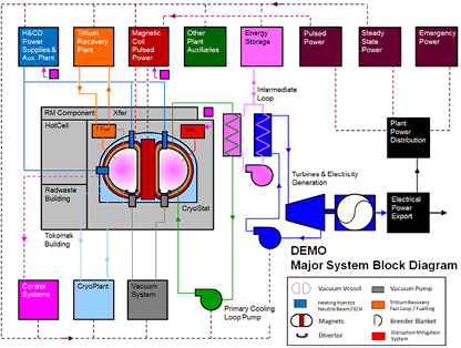
Figure 1. Schematic of a DEMO power plant.
Download figure:
Standard image High-resolution imageThe development of an advanced design which incorporates significant changes in comparison with existing practice would require more R&D, feasibility tests, and the willingness to take a higher risk. As most components or materials being used in ITER are not fully DEMO relevant, further developments beyond ITER (i.e. in safety, power exhaust, breeding, RH, availability) will often stem from imperative design drivers that cannot be compromised by lack of representative operating data. The impact on the overall plant reliability and availability of the various system design options must therefore be analysed in an integrated approach, with testing regimes developed accordingly. In other words, some gaps could remain between some first generation systems of DEMO and what is needed for the FPP. To bridge these potential gaps, DEMO must be capable of testing advanced technical solutions that will be developed in parallel for application in a fusion power plant, thus playing the role of a component test facility. For instance, the design and operation strategy now adopted for the breeding blanket as recommended in [3, 10] is to obtain licensing approval for operation up to moderate exposures that could be obtained for the 'starter' blanket, while high-dose engineering data for a more advanced materials blanket is being generated. In addition, the benefit of this 'progressive' approach would also include the possibility to start with a less optimized thermo-hydraulic or mechanics design (larger safety margin) to cope with large uncertainties in the overall reactor loadings and performances. In addition, it may be decided to extend the purely inductive pulse duration by auxiliary H&CD systems to be installed at a later stage. The benefit could be, for example, an extension of the service life of in-vessel components through a reduction of the number of thermal cycles—as a result of an increase of pulse duration. Such capabilities have to be properly investigated early in the conceptual design phase of DEMO.
To make prudent choices concerning the future path of fusion power, one should draw important lessons from the fission experience of developing and deploying reactor plants through successive generations. The fission evolution has been catalysed by the need for advances in safety, materials, technology and commercial attractiveness in addition to strong involvement of industry from the beginning. Different types of new nuclear plants are being developed today that are generally called advanced reactors. In general, an advanced plant design is a design of current interest for which improvement over its predecessors and/or existing designs is expected. Advanced reactors consist of evolutionary design5 and innovative designs6 requiring substantial development efforts. The latter are more ambitious and differ from evolutionary designs in that a prototype or a demonstration plant is required. The paradigm used in fission for the justification and the definition of the top level requirements of a demonstration prototype in fission are described in table 2 [14].
Table 2. Key requirements driving the design goal of a prototype in fission.
| Safety | Safety analysis of the prototype should be as similar as possible to the safety analysis of the commercial plant. |
| Plant availability | Prototype should reach high availability factors → this intrinsically pushes for conservative solutions with high TRL (i.e. reliability) from the very beginning |
| Components' lifetime | Component operation under nuclear conditions must demonstrate the potential to achieve lifetimes necessary for cost-efficient plant operation |
| Inspectability/ maintainability | Prototype should be designed with demonstrated inspection and RH sequences. |
In contrast to fission where the benchmark design point is represented by existing operating plants (mostly Gen II) with very high availability, the only broadly representative fusion plant that will exist in the next thirty years is ITER.
Tritium supply considerations are very important for defining the implementation timeline of a DEMO device, which must breed tritium from the very beginning and use significant amount of tritium (5–10 kg) for start-up. Tritium decays at a rate of 5.47%/year. Current realistic forecast of civilian tritium supplies available in the future points to very limited quantities of tritium available after ITER operation and in view of the limits above to start-up only one DEMO reactor this must operate and produce its own tritium in the early phase of the second half of this century [1, 15, 16]. Increasing supplies of tritium, by either extending the life of Canadian and South Korean CANDU reactors beyond 2030 or building new tritium-producing facilities, is clearly a controversial topic that lies outside of the fusion community's strategical control. In addition, the construction of any intermediate fusion device with a net tritium consumption in any part of the world during the next two decades (e.g. Chinese Fusion Engineering Test Reactor (CFETR) in China [17], or a burning plasma stellarator), will further limit the availability of the tritium supply.
3.2. Selection of technical design features and machine parameters
3.2.1. Initial point design studies.
The task of choosing an appropriate set of design parameters and engineering technologies involves trade-offs between the attractiveness and technical risk associated with the various design options. One of the crucial points is the size of the device and the amount of power that can be reliably produced and controlled in it. In general a larger device makes a number of the physics issues easier, but a smaller device will be cheaper and technologically easier to build. The preferred machine size is the subject of research and depends upon the assumptions that are made on the readiness of required advances in physics (e.g. the problem of the heat exhaust, choice of regime of operation, efficiency of non-inductive heating and current drive (H&CD) systems, etc.), technology and materials developments.
Two different DEMO design options are currently investigated, with emphasis on the first one, in an attempt to identify a realistic range of possibilities:
- A near-term DEMO (DEMO1) is a rather 'conservative baseline design', i.e. a DEMO concept deliverable in the short to medium term (e.g. construction possibly starting ~20 years from now), based on the expected performance of ITER (Q = 10) with reasonable improvements in science and technology; i.e. a large, modest power density, long-pulse inductively supported plasma in a conventional plasma scenario. The design of the BoP for a near-term DEMO must also make use of mature and reliable technology.
- A more advanced, DEMO design concept (DEMO2) based around more optimistic (but 'less mature') physics assumptions, which are at the upper limit of what may be achieved in ITER phase-2, i.e. an advanced higher power density high current drive steady-state plasma scenario. It is clear that this can only be delivered on a longer term (e.g. construction to be started on a much longer time scale assuming that the required significant advances in the physics and technology basis be demonstrated using ITER and the limited number of satellite fusion devices available in the next 10–20 years).
It is not to be inferred that two DEMOs should be built but rather that there is a need to incorporate some flexibility to mitigate the uncertainty in the design requirements for DEMO and maintain a vision of what is possible both in the near-term and on an extended timescale.
In comparison to the ITER (Q = 10) design, the European DEMO design options have significantly higher fusion power and stored energy, higher normalized plasma pressure (i.e. operate close to global stability limits), higher power radiated from the confined plasma region, and the radiation environment will limit the diagnostics available. Hence, aside from some simplifications of requirements (e.g. as DEMO will be designed for a much narrower range of operational regimes than an experimental device such as ITER), more challenging conditions in various fields will have to be faced. An EU assessment outlined five major 'DEMO physics issues' [18]. These are: (i) steady state operation; (ii) high density operation; (iii) heat exhaust; (iv) plasma disruptions; and (v) plasma control.
The DEMO design must be based as much as possible on the validated physics and technology basis of ITER, which should demonstrate robust burning plasma physics regimes, using a conventional divertor. The feasibility and performance of breeding blanket technologies is also expected to be partially demonstrated in ITER. In order to clearly identify and resolve DEMO physics challenges beyond ITER, the physics basis of DEMO needs to be developed, especially in areas with issues concerning the feasibility or the performance of the device [19].
Systems codes representing the full plant by capturing the interactions between (usually simplified) models of all the important plant subsystems are used to identify design points based on assumptions about plasma performance and technology. The systems code PROCESS [20] is being used to underpin EU DEMO design studies, and another code (SYCOMORE [21]), which treats some of the relevant aspects differently, is under development. Operating space and the consequences of choosing different target global parameters can be rapidly explored, as described in [22].
The system output is then analysed with state-of-the-art tools allowing a more detailed assessment of individual aspects in several areas (e.g. scenario modelling). In case of significant discrepancy with the systems code results, the parameters or modules used in the systems code are modified in order to obtain a better match with the more advanced calculations. This interaction is repeated until there is satisfaction with the realism of the design point, which can then be circulated as a 'stable release' for wider evaluation of both physics and engineering aspects.
Among technological constraints that strongly impact the design, there are the magnetic field in the superconducting coils, the allowable surface heat loads in the divertor and on the first wall, and the neutron load limits on the first wall and the structural materials of blanket and divertor. Some preliminary physics and engineering parameters are shown in figure 2, while design features now incorporated in the initial conceptual design work are listed in table 3, together with open design choices where a decision is expected to be made at a later stage.
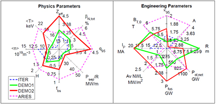
Figure 2. Physics (left) and engineering (right) parameters of an inductive and steady-state DEMO design option [10]. The values for ARIES are taken from [24].
Download figure:
Standard image High-resolution imageTable 3. Preliminary DEMO design features.
| Main design features |
| – 2000 MWth ~ 500 MWe |
| – Pulses > 2 h |
| – Single-null water cooled divertor; PFC armour: W |
| – LTSC magnets Nb3Sn (grading) |
| – Bmax conductor ~12 T (depends on A) |
| – EUROFER as blanket structure and AISI ITER-grade 316 for VV |
| – Maintenance: Blanket vertical RH / divertor cassettes |
| – Lifetime: 'starter' blanket: 20 dpa (200 appm He); 2nd blanket 50 dpa; divertor: 5 dpa (Cu) |
| Open design choices |
| – Plasma operating scenario |
| – Breeding blanket design concept |
| – Protection strategy first wall (e.g. limiters) |
| – Advanced divertor configurations and/or technologies |
| – Energy conversion system |
| – Specific safety features, e.g. # of PHTS cooling loops |
| −Diagnostics and control systems |
The machine size (major radius) is driven by various aspects. Among these are the quality of confinement, the edge safety factor, and the aspect ratio. Recently it has been found that the combination of the requirements to protect the divertor and to operate sufficiently above the L-H-threshold affect the machine size [23].
3.2.2. Systems code uncertainty and sensitivity studies.
The aspect ratio (A = R/a) was identified as one of the most important parameters which was still relatively unconstrained. Studies were carried out in 2014 in various areas to understand the advantages and disadvantages of aspect ratio variations between 2.6–4 on the pulsed DEMO design (see figure 3). Lower aspect ratio designs implying a larger plasma volume and lower toroidal field have a higher TBR, better vertical stability properties, and lower forces on in-vessel components during fast disruption events. Larger aspect ratio designs have the advantage that the gap between vessel and outer leg of the TF coil can be made smaller to achieve the same value of toroidal field ripple. The majority of data from tokamaks is available around an aspect ratio of 3.

Figure 3. Key design parameters for pulsed and steady-state design options in comparison to the ITER (Q = 10) design point.
Download figure:
Standard image High-resolution imageAlthough in depth assessments of some aspects (e.g. cost, maintainability, availability) still need to be carried out, the DEMO1 aspect ratio was changed from 4–3.1 in recognition of a favourable trend towards lower values of A. Investigating multiple design points is important at this stage and more work related to the choice of DEMO aspect ratio is in progress and may result to further modifications of the baseline design in the future.
The input parameters and also the relations used in systems code calculations are subject to important uncertainties. Various sensitivity studies are being carried out to identify the key limiting parameters, to explore the robustness of the reference design to key assumptions, to analyse the impact of uncertainties, and to analyse the trends and improve early design concept optimization.
3.3. Systems engineering framework
A project as large and complex as DEMO certainly warrants a systems engineering (SE) approach, especially given the multitudinous number of interdependencies it contains. The systems engineering process is shown in figure 4 [25].
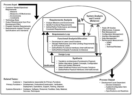
Figure 4. The systems engineering process [25].
Download figure:
Standard image High-resolution imageThe DEMO programme has to do two difficult things at the same time. It has to produce a coherent concept that is fully substantiated and resilient to scrutiny (requirement 1), whilst at the same time accommodate the fact that it exists in an environment where innovation and subsequent technological advancement are progressing continuously (requirement 2). The second point is underlined by the significant time duration between conceptual studies and the completion of detailed design, which might be 15–20 years or more.
A systems engineering framework can accommodate these themes with suitable definition of data and relationships between data points. In a practical sense, DEMO can be thought of as comprising of a plant architecture model (PAM) and a set of system level solutions (SLSs). The PAM is essentially the top level design of DEMO, setting out the main machine parameters, their justification, the main architectural features and the reasoning behind their inclusion and then the supporting systems in the form of high level block diagrams with identified performance requirements. The SLSs are then design solutions that respond to the needs of the PAM via a functional structure developed in the systems engineering framework. The PAM satisfies requirement 1 whilst the SLSs are identified from best available technologies and in this area, variants can co-exist and to some degree be evergreen (i.e. updated on a frequent basis) in alignment with requirement 2. At any particular time it is beneficial to state a reference technology, but this can easily change as refinement of the PAM will lead to changes in the basis of the reference selection, and another variant becoming more favourable. By capturing these relationships in a systems engineering framework, the relationships between the PAM and associated SLSs can be maintained.
One of the most important outcomes of this phase of the DEMO programme must be that it creates something that can be built upon in the next phase. It is essential therefore that one does not just simply record the design output of this phase, but record the thinking behind the design output in addition to purely technical deliverables. Without this context, a future team will take the output at face value and be unable to rationalize the context in which it was derived. Elements of the design will appear over complicated and even unnecessary unless there is traceability. A future team could well conclude the PAM to be unfit for purpose and start again. A systems engineering framework will inherently provide the traceability and justification to preserve the intent and subsequent concept the present team are striving to produce.
3.3.1. Stakeholder engagement and lessons learned from GEN IV.
Key to the success of any technology development program is the early and continuous engagement of technology stakeholders to ensure that the work conducted is valuable to the eventual adopters of the technology. A DEMO stakeholder group was established with experts from industry, utilities, grids, safety, licensing and operators to focus early on fusion energy research and development needs to address utility, regulatory needs and to establish from the very beginning realistic top level requirements for the DEMO plant in order to embark on a self-consistent conceptual design approach. This will ensure that their perspectives are captured in the initial identification of leading technologies, and the down-selection for the most promising design options. A stakeholder group report has been produced. This can be summarized as dictating the principle missions for the current DEMO programme as being: (i) safety and environmental sustainability; (ii) plant performance; and (iii) assessment of economic viability.
Before embarking on a stakeholder engagement process, a number of meetings were held with advanced Gen-IV Fission projects such as ASTRID and MYRRHA and the following lessons were learned:
- Fission projects follow a pattern of evolution in each successive plant design, with careful progression in key areas backed up by some operational data. ASTRID has drawn from Superphenix and the Phenix machine before that. MYRRHA has matured from extensive test bed development and operation of the MEGAPIE experiments.
- The plant design should drive R&D and not the other way round.
- It is important not to avoid the fact that fusion is a nuclear technology and as such, will be assessed with full nuclear scrutiny by the regulator. To this end, early engagement with a licensing consultant is needed to understand and tackle potential safety implications through design amelioration.
- There is a need for a traceable design process with a rigorous systems engineering approach. Decisions must be rigorously recorded in order to defend a decision path taken that was correct at the time, but in years to come, may seem wrong. Design choices should be made within a traceable context of functions and requirements so that future lurches from one decision path to another are not made without full understanding of the requirements originally assigned and the potential implications.
- The design of a plant aiming at production of electricity should be the main objective of the DEMO concept design work and supporting R&D—rather than aiming too high and promising something unachievable.
- The technical solution should be based on maintaining proven design features (e.g. using mostly near-ITER technology) to minimize technological risks, but both highlighted the need to take risks when the reward is significant and there is a back-up plan.
- Reliability and maintainability should be key drivers: allow for design margin (over-design) where technology limits and budget will allow, since this will increase machine longevity, reliability and capability, when considering enhancements.
3.3.2. Systems engineering approach for dealing with uncertainties.
A big challenge in the development of a DEMO concept is the combination of many design interdependencies and the inherent uncertainties. The combined effect is that uncertainty propagates through the design, often leading to de-harmonised boundary conditions between sub-systems being studied individually. From a practical perspective, a way forward is to determine some assumptions that allow conceptualizing to proceed, whilst at least being rooted in some sound logic that fits with the philosophy of the conceptual approach. Methods for tackling the challenges that uncertainties pose consist of:
- Tracking assumptions used in the design, their justifications, and where they are used so that at any future time, the basis for concepts derived from these assumptions can be retrieved. As assumptions mature to defined and reasoned values, the cascade of effects this development has on the overall design can be quickly and accurately identified.
- Understanding the relative impact uncertainty around different design points has on the physics design. Eliminating uncertainty is resource-heavy and so it is important to work on the high impact uncertainties. By varying input parameters, the effect on key performance metrics can be ascertained.
- Understanding the wider risk uncertainty poses. This extends the sensitivity studies previously described to include other facets of the design such as the safety or maintainability impact.
- Tracking uncertainty margins through the design. In order to compensate for uncertainty, margins are often applied to parameter values which if not monitored, can combine to form large multipliers in the boundary conditions of sub-systems.
Further discussion on treating uncertainties is in [26].
3.4. Safety and licensing considerations
The development of the safety case for DEMO can benefit from the experience of the licensing of ITER [27]. The extensive safety analysis performed by the ITER team to support the licence application represents by far the largest study of nuclear fusion safety ever performed. However, there are some important differences between DEMO and ITER (e.g. higher neutron fluence, tritium self-sufficiency, use of as-yet largely unqualified materials, much longer pulse length and very different coolant parameters, including the use of helium coolant in place of water in most design concepts) that may affect the safety approach and the safety provisions required in the design. Despite these differences, the extensive safety design and safety analyses performed for ITER, together with the experience of defending these before the nuclear regulator, provide a very useful starting point for DEMO safety studies. Further relevant information for studies of DEMO safety is provided by the extensive European studies of fusion power plant concepts, particularly between 1992 and 2005 (see for example [28, 29]). These programmes considered a wide range of conceptual designs for fusion power plants and assessed their safety and environmental impact, in particular by using computer models to analyse postulated accident scenarios to establish the bounding consequences.
Reliably preventing the release of in-vessel radioactive inventory, as well as others elsewhere such as the tritium inventory in the fuel cycle systems, is a key objective of the safety design [13]. It is achieved by application of the principle of Defence in Depth, in which multiple layers of protection and preventive actions are provided. For the in-vessel inventory, the first confinement system is provided by the vacuum vessel itself, further barriers being provided by the walls and slabs of the building, with the enclosed volumes being served by ventilation systems including high efficiency filtering and atmosphere detritiation systems. Details of the confinement approach for DEMO are still being elaborated. The minimization of occupational radiation exposure is a further important safety goal, maintaining any personnel doses as low as reasonably achievable (ALARA).
The final consequence of the neutron activation of a large quantity of structure and components is the generation of solid radioactive material that will require treatment and disposal at end-of-life, or during operation in the case of components that need to be periodically replaced. Some of this material is not only active but also contaminated with tritium, diffused into the bulk as well as at the surface. There is a potential to produce a rather large volume of low level waste. The strategy for minimizing this volume, as well as the level of hazard, involves the use of low activation materials for the components with high levels of irradiation, the minimization of the replacement of active components, and the optimization of neutron shielding to reduce the exposure of bulky ex-vessel components. Assuming a success of the on-going development of low/reduced activation materials, the majority of activation decays relatively quickly, and previous studies such as the PPCS have foreseen a storage period of 50–100 years after which the majority of the material could be removed from regulatory control according to clearance procedures. Much of the remaining materials could be recycled into components for future power plants, leaving only a small quantity of waste for disposal.
Whether or not this will be done for the one-off DEMO plant remains to be decided, but the programme includes studies of techniques for recycling to establish viable processes that may be demonstrated on a proof-of-principle scale. For those components that are not only activated but also tritium-contaminated, processes for bulk detritiation will be required and the candidate techniques are being studied, the most promising ones to be the subject of an R&D programme to bring them to maturity.
All these safety and environmental issues have an impact on design, so it is essential in the DEMO conceptual design activities that safety considerations are at the heart of design choices from the very beginning. This will result in a design that is not only licensable but also demonstrates the beneficial safety and environmental characteristics of fusion power.
4. Materials nuclear design requirements and effect of radiation damage for candidate DEMO design options
4.1. Performance requirements for structural materials for in-vessel components
The main materials relevant features and the requirements from the design of the current near-term DEMO are listed below [3, 6, 7]:
- High divertor power handling, i.e. the ability to withstand power loads larger than 10 MW/m2. To cope with this, use of water and copper alloys as in ITER is considered (see also section 5.1). The radiation damage from the neutronics simulations of the divertor show that the predicted damage for the tungsten divertor armour would be ~3 dpa/fpy, whilst if copper were the coolant interface material in the high-heat-flux components of the divertor, the radiation damage would be a maximum of about 5 dpa/fpy7, but would be as low as ~3 dpa/fpy in the strike zone areas [8, 30]. An important question that needs to be answered as soon as possible is whether the lifetime of the divertor is determined by erosion, as foreseen by the authors, rather than by structural integrity considerations.
- A near-term DEMO should act (at least) in its first phase of operation as a 'component test facility'. For example, it will utilize a 'starter' blanket configuration using moderate-performance materials (with the overall design configured such that this will not affect regulatory approval) and then switch to blankets with a more advanced-performance material after a limited accumulated MW yr/m2. A similar philosophy might be applied to the divertor. A 'starter' blanket should be designed using materials capable of withstanding ~20 dpa damage in the blanket front-wall steel. The second blanket should be capable of lasting up to 50 dpa.
- The replacement of blankets or divertors cannot be accompanied by a complete change of the BoP, as this is clearly unfeasible in a time-critical programme. Thus, the series of blanket concepts and divertor concepts must each assume the same coolant for the entire lifetime (although the divertor and blanket coolants could, in principle, be different).
An assessment of the state of development of and the R&D needs for neutron-resistant structural, high-heat flux and plasma-facing materials suitable for use in a fusion reactor is reported elsewhere (see e.g [4–7]). This assessment has focused on the urgent R&D needs for material development for a DEMO starting construction as early as possible. The assessment has defined a realistic set of requirements for the DEMO materials such as the capability of withstanding neutron damage up to 20 dpa (for blanket front-wall steel) and 5 dpa (for copper-alloy-based divertor heat sinks). The EU Materials Assessment Group (MAG), which advised and informed the EU Fusion Roadmap, has emphasised a risk-analysis-based, project and systems-engineering approach: considering whole system reactor operational cycles; needs for efficient maintenance and inspection; and interaction with functional materials/coolants.
The following strategy has emerged for the development of neutron resistant materials for DEMO in Europe [6, 7]:
- The selection of a limited number of baseline and risk-mitigation materials for structural steels, plasma-facing materials and heat sink materials interfacing the coolants, during Horizon 2020 on the basis of the results of irradiation in fission reactors. This should include fission neutron irradiation of samples doped with special isotopes (i.e.10B, 58Ni or 54Fe) to simulate effects such as H/He production and with the support of an adequate modelling effort.
- A strong emphasis shall be placed on the industrialization of the candidate materials, including issues of fabricability and joining techniques. Increased direct participation of industry as a full partner is highly sought to be pursued with high priority.
- There are important lessons to be learned from fission reactor material development, especially in safety and licensing, fabrication/joining techniques and development of manufacturing and supply-chain [31]. For fusion, ITER licensing experience can be used to refine the issues in nuclear testing of materials. It is necessary to develop a safety case focussing on the lightly-irradiated vacuum-vessel as the first confinement barrier for the in-vessel inventory of tritium and dust. This limits the scope of materials tests with fusion neutron ('14MeV') spectrum before DEMO design finalisation, to a focus on engineering-code support and development, rather than licencing. Nevertheless testing with 14MeV neutrons is essential to fusion materials development. To do this in a timely manner requires deployment of a ⩾30 dpa (steels) 14MeV testing capability by the middle of the next decade. The previously mentioned optimization of the testing programme by the pre-testing with fission neutrons on isotopically- or chemically-doped steels and with ion-beams is a necessary precursor to the 14MeV testing programme itself.
- The completion of the design of an accelerator-based 14MeV neutron source for the characterization of materials under a fusion neutron spectrum up to a level of damage typical of DEMO (although not of a fusion power plant). Options have been evaluated (such as a reduced specification version of IFMIF) to have the facility ready around the middle of the next decade and thus make available these data in time for the completion of the DEMO engineering design. This topic is discussed elsewhere in this special issue [32, 33].
In-vessel and vessel components have conflicting design constraints and requirements that must be satisfied. In particular, these are required to maintain structural integrity while operating within unique and harsh fusion environment. It has been recognized that there is a requirement for fusion specific design criteria to provide guidance for the unique design challenges seen within a fusion reactor. As discussed by Porton [34], the application of existing structural design criteria8 for nuclear environments (e.g. ASME BPVC III [35], RCC-MRx [36], SDC-IC [37]) to exemplar DEMO in-vessel components highlights key shortfalls at the interface of materials and engineering: (i) existing metrics fail to adequately describe component and material performance; (ii) a comprehensive library of materials data in relevant conditions does not yet exist; (iii) the current approach to material allowables restricts the available design space for the development of acceptable conceptual solutions. In response to this requirement, long term work has started to develop fusion specific design criteria. However, as the conceptual design of an EU DEMO has already commenced, there is a near term need for DEMO designers to have critical design guidance for the most environmentally challenging areas, specifically for the plasma-facing (PFC) components. These in-vessel components will have to operate in a new environment and will inevitably have to utilise novel high performance joining techniques and materials. Validation of these component designs will require comprehensive supporting structural design criteria, which possess the required damage mechanisms, modifying effects, joint techniques and material allowables.
For European DEMO designs it has been proposed that the ITER practice of establishing the vacuum vessel as the primary safety barrier with the necessary requirements to assure confinement, is applied to DEMO [6, 7] (see section 5.3). Based upon supporting neutronics simulations [38] that indicate substantial attenuation and moderation of the neutron flux between the first wall and the vacuum vessel (e.g. loss of two orders of magnitude with negligible fluence above 1MeV) (see section 4.2), this approach permits the vessel material to be qualified within a fission-neutron spectrum and to utilise precedented steels (e.g. 316L) whilst still adhering to end-of-life activation requirements. Demonstration of vessel structural integrity to the regulator, and compliance with the precepts of the safety case, would then be supported by existing or minor modifications to established pressure vessel codes (e.g. ASME BPVC-III, RCC-MRx) as occurred in the ITER case [39] and assuming the use of industry-standard practices such as defence-in-depth and passive safety across the plant design to underpin the vacuum vessel's primary confinement function. However, the case for in-vessel components is by contrast very different (see sections 5.1 and 5.2): in a demonstration power plant device the divertor and blanket will be developmental components, and therefore, these components should wherever possible not be credited with a safety function. This philosophy does not preclude that for future commercial fusion power plants, the plant operation and thus the in-vessel components must be highly reliable, implying that in due course such components may be credited with some safety function, if required [27].
Therefore, though their integrity is of relevance to the safety case given that they are a source of postulated initiating events, verification of the integrity of the in-vessel components within a demonstration power plant is driven by the need to demonstrate appropriate reduction of operational/economic risk, rather than compliance with the safety case and the assurance of public safety. This presents, if the particular issues of country-specific regulation are set aside for the purposes of this paper, freedom in the approach to verification and allows departure from the currently available structural design criteria.
In the ITER case this resulted in the production by the ITER parties of the ITER structural design criteria for in-vessel components and supporting specifications in order to address the specific features of the ITER design and operating conditions [39]. Likewise in the case of DEMO, this necessitates a new approach that is particular to the challenges of that device with respect to structural integrity and the collection of supporting material data.
The development strategy being undertaken in this area is described in [40, 41].
4.2. Neutron transport and inventory calculations
To highlight the complexities associated with material selection, and to investigate the implications associated with the choice of concept, we have performed a series of neutron-transport and inventory calculations to trace the variation in transmutation, activation, and radiation damage evolution for in-vessel reactor materials. Figure 5 shows the finite element geometry (for neutron transport modelling with MCNP) of a typical DEMO used to study four different combined cooling and tritium breeding concepts (see below). The four concepts have different material compositions for their homogeneous blanket cells (green in figure 5), and the compositions used for this study (based on the 2013 concepts within the European design projects) are:
- HCPB—helium-cooled reactor with a ceramic pebble-bed blanket of Be and Li orthosilicate (43.6% Be, 9.7% Li4SiO4, 36.9% He, 9.8% EUROFER by volume)
- HCLL—helium-cooled reactor with a liquid LiPb blanket (85% LiPb, 7% He, 8% EUROFER)
- WCLL—water-cooled reactor with a liquid LiPb blanket (85% LiPb, 5% water, 10% EUROFER)
- DCLL—dual coolant reactor with a self-cooling liquid LiPb blanket and helium cooling elsewhere (85% LiPb, 3% He, 4% SiC, 8% EUROFER)
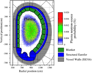
Figure 5. 2D slice through the model geometry of a DEMO design developed at KIT, Germany. The neutron transport code MCNP was used to simulate the neutron-irradiation field in the different finite-element cells of the model, using the plasma source probability distribution shown in the plot and the correct 14.1 MeV-peaked Gaussian energy distribution.
Download figure:
Standard image High-resolution imageThe base template for all concepts is a 2.0 GW reactor with a plasma major radius of 9 m and aspect ratio of 3.6. The FW is predominantly EUROFER steel with a thin armor layer of W. The divertor is W-based with water cooling (40% by volume of structure), and the walls of the vacuum vessel are SS316 steel. Note that to guarantee the correct tritium breeding ratio (TBR) in excess of unity, the amount of 6Li enrichment has been varied with concept. The HCPB required 60% enrichment, while the three liquid LiPb concepts have 90% enrichment.
For each model neutron spectra were tallied in all regions of interest, including the first wall (FW) armour, divertor (all regions), and vacuum vessel (VV) walls. Subsequently, these spectra have been used as input for detailed inventory simulations of the transmutation, activation, and damage rates in materials using the FISPACT-II [42] inventory code developed at CCFE.
FISPACT-II can calculate, using the latest in-built damage cross section libraries, the displacements-per-atom (dpa) measure of irradiation dose for the full nuclide inventory. This measure, while limited in its ability to fully quantify radiation damage, is nonetheless a useful integral quantity that allows approximate assessment of the respective damage doses experienced by materials under different neutron fields, and has been shown to correlate well with certain experimental trends.
Figure 6 compares the dpa/fpy value in EUROFER as a function of poloidal position in the FW of the four different concepts, figure 7 gives equivalent values for the SS316 in the VV walls, and figure 8 values for tungsten (W) in the divertor. The results for the FW show that there is some variation as a function of concept, with the liquid LiPb breeding concepts generally leading to more damage exposure for the FW compared to the ceramic breeder concept, which is caused by increased back-scatter and reduced neutron moderation (the Pb increases the scattering in the LiPb concepts, while the Be improves moderation in the ceramic concept).

Figure 6. Poloidal variation in dpa and He production (in atomic parts per million—appm) per fpy in the EUROFER steel of the FW. Calculated by FISPACT-II using the TENDL2014 [45] nuclear data libraries.
Download figure:
Standard image High-resolution image
Figure 7. Poloidal variation in dpa/fpy during irradiation and dose rate at 100 years following a 10 fpy irradiation in the SS316 steel of the vacuum vessel walls of the DEMO9. Calculated by FISPACT-II using the TENDL2014 [45] nuclear data libraries.
Download figure:
Standard image High-resolution image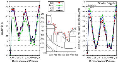
Figure 8. Poloidal variation in dpa/fpy during irradiation and dose rate at 100 years following a 2 fpy irradiation in the W armour of the divertor. Calculated by FISPACT-II using the TENDL2014 [45] nuclear data libraries.
Download figure:
Standard image High-resolution imageThe picture is somewhat different in regions further from the plasma-facing surface. Figure 7 shows that the water-cooled concept provides significantly more protection on average through the thickness of the VV compared to the helium cooled models. Note, however, that this result is strongly dependent on the exact nature and thickness of the shielding between the plasma face and the vacuum vessel and would have to be carefully optimized for each concept. On the other hand, in the present models, even for the helium cooled blanket concepts, the dpa in the SS316 steel on a typical 30 year reactor lifetime is less than 0.01 dpa/fpy in the thick, homogenized VV cells, and so it would appear that the total damage over a typical 30 year lifetime will not approach the 1 dpa level—a level that is known to have property-changing consequences for some materials, including steels [43]. However, the exact damage accumulated is likely to vary significantly in more heterogeneously modelled VV regions, and it has been shown, for example, that the dpa rate in the most exposed inner-shell of the VV can be as much as 0.2 dpa/fpy [44], and in this case the damage during operation lifetime would produce a change in mechanical properties.
However, the concentration of helium produced by transmutation in the vacuum-vessel is expected, with the fairly 'soft' neutron spectrum incident, to be very low (~10–4 appm/fpy) [30] which opens up the possibility of using a fission spectrum neutrons to evaluate the resultant deterioration of properties.
The calculations for the W armour of the divertor in figure 8 indicate that there is very little variation between the different concepts (maximum variation of around 30%) because the particular blanket concept has almost no influence on divertor exposure, although there is significant variation with position within the divertor. For example, the most exposed regions of the divertor experience around 5.5 dpa/fpy in W, while in the relatively well shielded (from neutrons) high heat-flux regions the dpa/fpy in W can be less than 1.0.
Figure 6 also shows the results of inventory calculations to measure the helium-gas production rates in the FW EUROFER. There is very little variation with concept, although the He:dpa ratios would be somewhat different because of the variation in dpa/fpy already discussed. As with the dpa predictions, the highest He production rates are observed for the equatorial regions of the FW, where around 125 atomic parts per million (appm) He is produced during a single fpy irradiation. Such gas-production levels are likely to increase swelling and brittleness of the FW components, but given the similarity between the different concepts, it may only be mitigated by careful selection and engineering of the FW itself, rather than by any change to the tritium breeding or cooling choices.
Figure 8 also shows the contact dose, measured in micro Sieverts per hour, from the W armour material after 100 years of cooling, assuming a 2 fpy divertor lifetime [46]. Again, there is little variation between concept, and the dose in all regions is at or below the 10 μSv/h dose limit for hands-on contact, based on a 2000 h working year and an individual dose limit of 20 mSv/yr [47]. From figure 7, one sees that for the water-cooled concept most regions of the VV wall are below this 10 μSv/h at 100 years cooling following a 10 fpy (an optimistic estimate assuming a total FW lifetime of 70 dpa but in reality the first wall would need to be replaced earlier) irradiation of SS316. However, for the three helium-cooled models, many of the VV regions—particularly those not shielded by the divertor—are more than an order of magnitude above this limit at 100 years, which may indicate that additional shielding would be required to protect the VV in these cases.
Figure 9 considers the dpa/fpy and 100 year contact dose rate after a 2 fpy irradiation for pure Copper as a result of exposure to the various heat sink regions of the divertor, which are the visible '2nd-layer' cells, immediately behind the W-armour. In the right-hand plot, in particular, which shows the 100 year contact dose rate, the mSv/h scale reveals that Cu would be at least three orders of magnitude above the 10 μSv/h hands-on dose limit. Note that in the MCNP model these 2nd layer regions were only 1% (by volume) Cu and for a proper evaluation of the implications of using more Cu, perhaps as part of an alloy such as CuCrZr, the MCNP model and calculations should be modified.
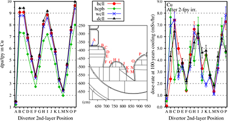
Figure 9. Variation in dpa/fpy during irradiation and dose rate at 100 years following a 2 fpy irradiation of Cu under the conditions predicted in the various regions of the divertor 2nd layer (immediately behind divertor armour).
Download figure:
Standard image High-resolution imageFinally, in figure 10 a comparison of the 100 year, post 2-fpy irradiation, contact dose rate as a function of position within the divertor structure for EUROFER is shown (the current choice in the model, which is 60% by volume of the structure with water the remainder) and SS316 using the same irradiation conditions (no new MCNP calculation was performed for SS316—only the input material to the activation calculations is different). The use of SS316 is considered here because the use of low temperature water in the divertor would aggravate the problem of embrittlement of EUROFER, even though irradiation levels in this regions are expected to be relatively low. Both show dose rates that exceed the 10 μSv/h limit (note the mSv/h scale in the plots), but SS316 is higher by around a factor of 4 in the most irradiated regions. This implies that extra shielding would be required to make the desirable use of SS316 acceptable.

Figure 10. Variation with divertor structure position of the dose rate at 100 years in EUROFER and SS316 steel following a 2 fpy irradiation.
Download figure:
Standard image High-resolution image5. Materials and design issues for critical technologies for DEMO reactor applications
Designing the interface between thermonuclear plasma and the solid material environment is arguably one of the toughest challenges for ITER and even more for the successful development of DEMO and future fusion power reactors. The need to absorb large amount of nuclear power and effectively to exhaust plasma heat and, in particular, to withstand localised surface heat requires in the affected areas very efficient cooling technologies and relatively thick high heat flux components and this in turn reduces the available surface area used to efficiently breed tritium and extract power. This in turn strongly impacts the selection of the materials and PFC technologies, the definition of operating conditions of the structural materials/components and the selection of coolants [48, 49].
Some of the key materials and technologies issues that need to be addressed in particular in the design of the in-vessel components and the vacuum vessel of a fusion reactor are briefly summarised below. The design issues and strategies for DEMO in-vessel component integration is described elsewhere (see for example [50]). Examples of challenging design constraints that affect these internal components are:
- they cannot have any leaks without spoiling the vacuum;
- they must tolerate significant heat flux and plasma erosion of surfaces, including off-normal events like plasma disruptions that produce severe surface energy pulses;
- they must be replaceable in reasonably short times (this applies mainly to the in-vessel divertor and blanket components, which are foreseen to need replacement after the equivalent of 2 fpy operation);
- they are damaged by fusion neutrons and plasma particles, and so have evolving material properties and a limited lifetime.
- they have complicated geometries to conform to the poloidal shape of the tokamak plasma and accommodate toroidally many penetrations for plasma fuelling, heating, and instrumentation equipment; and
- they are electromagnetically coupled to the plasma in complicated ways and so must be designed for compatibility with plasma operations, including off-normal events like plasma disruptions that induce severe electromagnetic forces.
5.1. Divertor and first-wall
Developing a reactor compatible divertor has been identified as a particularly challenging physics and technology problem or magnetic confinement fusion [1, 46]. In all current fusion device designs the power that crosses the magnetic separatrix (the last closed magnetic flux surface) is diverted along the magnetic field line to a remote region (the divertor) where it is exhausted on actively cooled divertor targets (see figure 11 below from [51]). The heat flows in a narrow radial layer of width λq (~few mm at the midplane assumed in ITER) called the scrape-off layer (SOL), which does not vary significantly with machine size. This thin scrape-off-layer and associated divertor plasma must dissipate the heat and particle flux coming from the fusion core while providing boundary conditions supporting the required fusion gain. Studies show that the majority of the fusion-alpha heating power must be dissipated before the plasma reaches the material surfaces to reduce material erosion to acceptable levels and avoid surface melting. The quantitative predictive scientific basis for meeting this challenge still remains to be fully established.
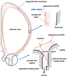
Figure 11. Poloidal cross-section of a tokamak plasma with a single magnetic null divertor configuration, illustrating the regions of the plasma and the boundary walls where important PMIs and atomic physics processes take place. The characteristic regions are: (i) the plasma core, (ii) the edge region just inside the separatrix, (iii) the scrape-off-layer (SOL) plasma outside the separatrix, and (iv) the divertor plasma region, which is an extension of the SOL plasma along field lines into the divertor chamber. The baffle structure is designed to prevent neutrals from leaving the divertor. In the private flux region below the 'X' point, the magnetic field surfaces are isolated from the rest of the plasma. (Reproduced with permission from [51]).
Download figure:
Standard image High-resolution imageDEMO must typically exhaust ~500 MW of heating power (fusion-alpha particle power and auxiliary heating power). If 40% of the exhaust power is radiated inside the magnetic separatrix, 300 MW will flow in the SOL. Approximately two thirds of this power (200 MW) is deposited on the divertor outer target, and one third (100 MW) on the inner target. In order to achieve an acceptable heat load on the divertor targets, the latter are inclined at a shallow angle with respect to the magnetic field lines and located in a region near the separatrix X-point (magnetic null point) with significant magnetic flux expansion. In this way the wetted area of the divertor targets in DEMO can be increased up to 1–2 m2. Thus, if all the heat entering the SOL ultimately ends on the divertor target (attached divertor regime), the power load would be  20 MW/m2. However, such a value is above the present technological capability of ~20 MW/m2 for steady state power load based on water-cooled copper alloys and can only be accommodated for relatively short time <10 s (i.e. slow transients). To further reduce the heat load, part of the power flowing in the SOL has to be radiated in the divertor, leading to the so-called partially detached regime. This requires plasma temperatures in the proximity of the divertor target below 10 eV. Low temperature, detached divertor conditions also reduce the erosion of the divertor armour. The main erosion mechanism in the divertor is physical sputtering by plasma and impurity ions. These impinging particles transfer energy to the atoms of the armour materials. If the transferred energy is large enough the target atoms can overcome the surface binding energy and leave the surface. The plasma temperature in front of the target defines the energy of the impinging particles by their Maxwell distribution and by the additional acceleration of the charged particles experience in the so called plasma sheath in front of the surface. For plasma temperatures below 5 eV, physical sputtering approaches zero for tungsten as an armour material and a typical impurity composition in fusion plasmas. Another important function of the divertor is that of particle control that is to provide adequate pumping capability to exhaust the neutralised gas, most notably the He ash, as well as to retain eroded impurities such that they will not enter the main plasma, which reduces performance and can lead to plasma instabilities. Plasma physics and control development is required to obtain usable scenarios in which the detachment can be achieved stably.
Several solutions for the heat exhaust in DEMO are presently being explored as part of the Roadmap Horizon 2020 [52]: (i) Baseline divertor solution—a combination of radiative cooling and detachment; (ii) innovative magnetic divertor configurations to achieve higher flux expansion spreading the heat over a larger area or to achieve longer divertor connection lengths and larger divertor radiated power; (iii) advanced plasma-facing components (PFC) (e.g. liquid metals) that could exhaust higher heat loads. However, it should be noted that the physics basis and the technology readiness level of the last two solutions remain very low and their design relevancy in terms of design constraints arising from DEMO integration and operation issues requires a deeper scrutiny, if and when they are proved to work in a realistic proof of concept tokamak.
The major material and design issues generally associated with the different high heat flux materials are discussed elsewhere in this special issue [53, 54]. Here, we focus on the aspects of the design that affect the selection of materials and the choice of operating conditions.
Typically, a divertor targets consists of a plasma-facing part (armour) that has to withstand the interaction with the plasma power and particle loads and is subject to erosion, and a heat sink (i.e. the coolant confining structure) which must extract the heat from the component and is subject to numerous engineering constraints. The value of the heat flux at the divertor and the anticipated range of variations set the specific materials and technologies to be used for the target design, the choice of the coolant and the definition of the coolant operating parameters.
Significant progress has been made during the last two decades on the development of technologies for divertor high-heat-flux components cooled with water. Prototypes fabricated with tungsten armours on Cu-alloy heat sinks, have been successfully tested under cyclic loads up to 20 MW/m2 for use in ITER [55, 56]. In the latter case, solutions have been found that can withstand 20 MW/m2 for about 500 cycles. It should be recognized that these values are close to the ultimate technological limits set by the intrinsic limitations of the thermo-mechanical properties of the limited number of materials suited for this application in the fusion environment. Taking into account that these properties will degrade under neutron irradiation already at the level of a few displacements per atom (dpa), and considering additional design margins that need to be included for a reliable target design (e.g. to accommodate for transients, for tile misalignments etc.), the power handling limits above must be reduced to about 10 MW/m2.
While it is to be expected that operation experience in ITER will lead to a much more robust control of detachment, realistically a few slow transients representative of loss of detachment should also be expected in DEMO. Thus, as far as power handling during steady state or long transients is concerned (typically lasting more than the thermal diffusion constant of the components which is typically several seconds), the divertor must be designed to guarantee adequate heat removal capability under any type of plasma regime (i.e. detached or at least transiently in attached mode of operation), which translates to much higher thermal loads near the strike point regions.
A water-cooled divertor in DEMO, using high thermal conductivity heat sink such as Cu-alloys, has much superior power handling capabilities than helium cooling and can absorb much larger slow transient heat fluxes (e.g. transition from detached to attached plasma, for up to a few seconds) which would easily exceeds the heat removal capability of helium-cooled targets to tolerate such excursions. However, removing tritium from water poses a particular problem as the absorbed tritium has to be separated from a huge quantity of stable hydrogen. Water and especially steam are likely to attack the pipes chemically and may well dissolve highly activated corrosion products. The oxygen forms 16N when irradiated by neutrons. This reaction is not very significant for fission reactors as it has a neutron energy threshold of 10.5 MeV, but becomes important for fusion, which produces neutrons of 14 MeV. The 16N has a half-life of only 7.1 s, but it emits penetrating gamma rays at 6.1 and 7.1 MeV.
An additional critical issue in the design of water-cooled components is the transition from nucleate boiling (two-phase flow) to the boiling crisis or 'burnout'. The burnout is characterized by the collapse of the heat transfer and the resulting sudden temperature excursion of the heated material. Cu based heat sink materials melt immediately. The threshold heat flux for this to occur is called the critical heat flux (CHF) [57, 58]. Depending on the component design, the concentration of the heat-flux from the loaded surface to the inner cooling wall results in a peaked heat flux at the inner cooling wall and CHF could occur for moderate incident heat fluxes. The local CHF strongly depends on the coolant velocity, the coolant pressure, and the local coolant temperature. The coolant velocity is limited either by engineering constraints like erosion by corrosion of cooling tubes or by the pumping power needed to maintain the coolant flow. To achieve a sufficient safety margin against the CHF the inlet temperature has to be less than 150 °C [59].
Therefore, the operating conditions of the divertor must be set as a compromise between keeping sufficient margins w.r.t. the critical heat flux (Tin ~ 150 °C) and maintaining sufficient structural integrity during irradiation. Traditional design rules for the case of Cu-alloy, based on the limited available irradiation data at relevant conditions, require operation in a temperature range between 150–200 °C (to minimise radiation embrittlement) and 350 °C, above which material properties deteriorate. A modern engineering design approach and design rules, to be further developed, instead of the conservative historical approaches, is required as there are numerous instances where low ductility occurs while the fracture toughness is high (see, e.g. [60]). Analyses should consider the full range of applicable situations including low ductility scenarios as well as crack propagation.
Although much less prone to high power and particle loads, the first wall protecting the blanket will also receive power from radiation and particles and will undergo erosion. For ITER, Be melting and excessive erosion can hamper operation whereas for DEMO the choice of the plasma-facing material as well as the cooling technology depends critically on the particle spectrum and the total absorbed power. Therefore all solutions envisaged for the power exhaust in the divertor must also treat the main chamber issues in a consistent way. Unfortunately, there are still very large uncertainties on the magnitude of the thermal loads at the main chamber wall. This could lead to the requirement of high heat flux protection in some areas of the wall, reducing the local breeding capability [10]. In addition, the uncertainty of the spatial distribution of the thermal loads makes the design of the components for an optimum power extraction very hard, if not impossible (see section 5.2).
5.2. Tritium breeding blanket
The breeding blanket occupies about 90% of the surface area surrounding the plasma and captures the large majority of DT neutrons that are produced in the plasma. It has an integrated first wall (FW) facing the plasma that also captures a portion of the surface energy flux from the plasma. The remaining portion of the surface heating is concentrated on the divertor, designed to take very high surface power loads (see section 5.1).
The main functions of the blanket/fuel cycle system can be summarised as follows:
- Tritium breeding and heat production: utilize and manage fusion neutrons by breeding tritium, converting neutron energy to heat. This region is exposed to high neutron fluence, especially in the first ~20 cm closest to the plasma.
- Tritium and heat extraction: generate high-grade heat suitable for conversion to electricity through a heat exchanger and turbine cycle extract tritium from the breeding blanket and send it to the purification and recycle loop. High-temperature power extraction must be accomplished using components and materials that do not damage the potential to continuously breed the tritium fuel. For instance, using thick structures and plasma-facing surfaces to increase strength and absorb energy is not possible because of parasitic neutron absorption and the resultant decrease in tritium breeding potential.
- Neutrons and radiation shielding: the breeding blanket contributes with the divertor to the shielding of the vacuum vessel, magnets and other equipment outside the reactor from nuclear radiation.
The breeding blanket is one of the most important and novel parts of DEMO. Large gaps in the required database would exist even with a successful TBM programme. In view of the existing performance uncertainties and feasibility concerns, R&D must be strengthened and a selection now is premature, without conducting the required R&D. A sustained programme of technology R&D is required to reduce the risks to the DEMO blanket development that cannot be fully explored in ITER, and/or to develop adequate knowledge to evaluate alternatives to the mainline concepts. R&D and design activities foreseen in Europe on breeding blanket are being implemented [61]. The ambitious goal is to achieve a down-selection of blanket concepts (including design integration and BoP feasibility assessments), to reach a single, most promising concept by 2020. If, as a result of the design and R&D work, a different breeding blanket module needs to be tested in the ITER TBM programme, this will have to be done during ITER phase-2 with a delay of the DEMO blanket development programme. Possible risk mitigation may arise from some sharing of information on the TBM programme among the ITER parties. In addition, China is designing CFETR [17] and this facility should start tritium operation around 2030. Options for potential participation in the exploitation of such a facility, for example, by testing alternative blanket concepts should be seriously pursued.
As discussed previously, it is currently proposed [3–6, 10] to utilize a 'starter' blanket configuration using moderate performance structural materials and then switch to blankets with a more qualified and/ or advanced performance structural material after a few MW yr/m2. This type of approach has been used for the fuel cladding in fission reactors for many years; by limiting the maximum exposure level of the replaceable cladding to below the regulatory limit, while data for higher exposure operation is generated in test reactors or load test assemblies. This approach benefits from the multiple-barrier safety approach in fission reactors, including the pressure vessel as a key safety boundary for regulatory approval. As section 4.1 shows, licensing approval for operation up to moderate exposures could be obtained for the 'starter' blanket, while high-dose engineering data for a blanket made from more advanced materials is being generated. In addition, the benefit of this 'progressive' approach would include the possibility to start with a less optimized thermo-hydraulic or mechanical design (higher safety margin) to cope with large uncertainties in the overall reactor loadings and performances.
The major material and design issues generally associated with the different breeding blanket concepts are discussed elsewhere in this special issue [62]. They can be summarised as follows [63].
5.2.1. Solid breeders blankets (e.g. HCPB, WCPB).
This concept includes a combination of a ceramic breeder, a beryllium-based multiplier (e.g. Be or Be-alloys) and a ferritic/martensitic steel as structural material. The ceramic breeder and Be multiplier can be in the form of sintered blocks or pebble beds. Currently, the main candidate breeder materials are (in the order of decreasing lithium density): lithium orthosilicate (Li4SiO4) and lithium metatitanate (Li2TiO3). In general solid breeders (with Be multipler) have manyadvantages: (i) they require smaller radial thickness and 6Li enrichment (40% in case of Li4SiO4) to achieve a sufficient tritium breeding ratio (TBR ~ 1.14), due to the favourable neutron multiplication characteristic of Be (see [64]); (ii) they rely on a simple and efficient mechanism of tritium extraction from the ceramic pebbles with a low pressure He purge flow; (iii) they offer better control of the parasitic permeation of tritium to the coolant that is a safety issue and consequently the possibility of avoiding the need for permeation barriers; (iv) they reach higher energy multiplication in the breeder zone that would help increase the total plant efficiency. On the other hand the critical aspects are: (i) chemical compatibility between the Be multiplier and water/air if water is used as a coolant or in case of air/water ingress in an accident scenario, with hydrogen production due to the Be-water reaction as a potential safety issue; (ii) tritium production, release and trapping characteristics of the breeding material and Be multiplier. Tritium permeation to the coolant is also an important issue; (iii) thermo-mechanical interactions between the pebbles and the structure including neutron irradiation effects, as thermal and mechanical property degradation will affect temperature control and thermo-mechanical performance, setting limits on the allowable power density due to the relatively low thermal conductivity of the ceramic breeder and on the blanket lifetime due to irradiation damages in the ceramic breeder and beryllium; (iv) Li burn-up in the ceramic; (v) cost of fabrication and necessary re-processing of the ceramic breeder and beryllium multiplier, since for tritium breeding reasons, the lithium contained in this material must be enriched to 30–60% 6Li (above the natural level of 7.5%); (vi) compatibility of Be with structural material; (vii) availability of Be material to be used in future reactors (hundreds of tons per device) [65].
In light of the above, currently the most promising ceramic blanket concept in Europe is the helium cooled pebble bed (HCPB) [61] which is one of concepts that Europe is planning to test as part of the ITER blanket test programme. A water cooled concept is instead proposed by Japan.
5.2.2. Liquid breeders.
The eutectic lead-lithium alloy LiPb is one of the most attractive breeder/multiplier materials due to its good tritium breeding capability, its relatively large thermal conductivity, and its relative immunity to irradiation damage. Nevertheless, there are issues of Li burn-up, of transmutation and of activation (direct or due to corrosion products) that require methods for chemical control/purification. It can lead to tritium self-sufficiency without employing additional neutron multipliers and allows for tritium extraction outside the vacuum vessel. LiPb has also the advantage of being almost inert in air and of having only a relatively mild and controlled reaction with water. In addition, LiPb can also be used as a coolant in advanced concept (see below). The following main types of near-term application blanket exist:
- He-cooled LiPb blanket (HCLL): This concept relies on a liquid metal LiPb that acts as a breeder and He as a coolant. This blanket will be tested in ITER in the form of test blanket modules (TBMs) [66].
- Water-cooled LiPb blanket (WCLL): This concept relies on a liquid metal LiPb that acts as a breeder and water as a coolant. The main issues are the control of the LiPb water interaction in case of an accidental guillotine rupture of a cooling tube, the control/ minimisation of the tritium permeation from LiPb to water and the risk of embrittlement of the selected steel as structural material resulting from operation at temperature lower than 350 °C. The first two issues can be alleviated with appropriate counter-measures such as dimensioning the LiPb container to the water-pressure, using double-wall tubes as coolant pipes (increasing the blanket reliability and availability at the same time), and applying tritium permeation barriers on the cooling tubes.
- Dual-coolant LiPb blanket concept (DCLL): This concept relies on a LiPb breeder/coolant that is flowing sufficiently fast to remove both the bred tritium and the majority of heat from the reactor. A second helium coolant is used to cool the structures especially the plasma exposed front part (i.e. the first wall). In this case, the MHD pressure drops in flowing LiPb are minimised by using SiC inserts that do not have structural functions. Degradation of thermal conductivity of SiC-composites by neutron irradiation should not be a problem since this material serves here only as a thermal insulator. However, helium transmutation in SiC is very large and resulting effects must be better understood. The main issue is the limitation due to the maximum allowable first wall temperature and from the compatibility of the structural material with LiPb, limiting the allowable interface temperature to about 550 °C. Use of oxide-dispersion-strengthened (ODS) steels with their higher strength-based temperature limit would increase operation capabilities, but welding requirements would make the fabrication more difficult.
Main common issues of the liquid metal blanket concepts mentioned above are: (i) corrosion of the pipes and blanket structures by circulating LiPb; (ii) efficient extraction and purification of tritium from LiPb at high temperature; (iii) control of tritium leakage and minimisation of permeation to coolants; (iv) control of Polonium and other transmutation products in irradiated LiPb; and (v) cost of 6Li enrichment, as LiPb concepts rely on up to 90% of 6Li enrichment to minimise the radial thickness of the breeder zone.
The choice of the breeding blanket coolant in DEMO has a substantial impact on the design and materials selection, operation, maintenance, safety and economics of the plant. Technical issues influencing the choice include: (i) thermal power conversion efficiency; (ii) pumping power requirements; (iii) power handling requirements of the first-wall; (iv) n-shielding requirements; (v) achievable tritium breeding ratio; (vi) breeder tritium extraction; (vii) tritium permeation and primary coolant tritium purification and control; (viii) chemical reactivity of coolant and breeder / coolant leakage; (ix); compatibility of coolant and structural material in the given operation conditions of temperature and neutron irradiation; and (x) design integration and feasibility of BoP.
An important decision in the evolution of the first wall/blanket design is whether or not to make the first wall hydraulically and mechanically integrated with the blanket. A first wall blanket design with an easily separable first-wall is, in general, much more complex than one in which the first wall and blanket are integrated both mechanically and hydraulically. The design of a first wall that can be separated from the blanket represents a very complex challenge (i.e. large amount of structural material and coolant will be detrimental for the breeding capability; will require more radial space and access to permit simple first wall removal operation (increase reactor size for a given neutron wall loading). However, in view of the uncertainties of the first wall thermal loads described above, it may be needed to hydraulically decouple the circuits aiming at the removal the surface heat (first wall) from the rest of the blanket circuit. This could lead to the necessity of using water to exhaust heat from localised areas to be protected with limiter-like structures (see section 5.1).The major material and design issues generally associated with the different breeding blanket concepts for near-term applications being considered can be summarized as follows.
The large uncertainties in the heat load distribution and/or large expected peak values of the local heat deposition in some areas challenge the design of the cooling system for energy production. Values of heat flux much larger than 1 MW/m2 are at the limit of the present technology (materials, performance, etc.) especially for helium, and by using water cooled first wall protection the power handling is marginally higher, except copper alloys are used as heat sink.
For a given power the coolant mass flow is determined according to the  (and related coolant conditions) that is required. The coolant velocity is limited either by engineering constraints like corrosion of cooling tubes, or vibration, or by the pumping power needed to maintain the coolant flow. The pumping power should be limited to a small fraction of the thermal power to avoid a decrease of the overall plant efficiency and to limit power recirculation in the reactor. The outlet temperature is limited by allowable maximum temperature of materials and design considerations such as thermal expansion that affect design layout and mechanical connections. The thermohydraulic design aims at keeping a constant target coolant ΔT (Tout − Tin) to ensure optimum operation of the power generation system. For the blanket, a typical
  for helium is ~200 K (T inlet/outlet 300–500 °C @8 MPa), and for water at PWR conditions
  is about 40 K (285–325 °C @15.5 MPa). In the design it is indispensable to know the power distribution in the cooling channels with sufficient precision. Large deviations and uncertainties degrade the performance of the cooling (and at a certain point they make the integration in a power generation system impossible!). Determining the plasma conditions and associated power loadings during normal and transient plasma operations (with a reasonably high degree of certainty) is vital, as these will guide the requirements for the design of the power extraction components.
The power extraction system in a fusion reactor has also to cope with the problem of tritium contamination. In fact, in most of the proposed blanket systems the breeder and the coolant loops are completely separated, to have a more efficient tritium extraction and avoid recovering tritium from large quantity of coolant. Nevertheless, potentially large quantity of tritium can permeate from the breeding to the cooling loop due to high temperature and large permeating surface. This parasitic effect has important safety implications in term of possible tritium release in the environment through the secondary loops (e.g. through the steam generator) and limit of tritium inventory in the coolant; this effect has to be minimised in the design decreasing the permeation rate to only few percent of the production rate. In addition, corrosion and erosion transmutation products can contaminate the coolant, requiring a continuos purification.
5.3. Vacuum vessel
The vacuum vessel is a large structure that contains the fusion plasma, allows for good vacuum conditions to be created, and serves as a safety confinement barrier for radioactive materials. It captures only a small amount of the total energy (3%), which is typically removed with a low temperature coolant and discarded as waste heat. The vacuum vessel, shielded as it is by the blanket, will only undergo relatively low irradiation in its lifetime, and generally with a much softer spectrum than the first wall (blanket and divertor) materials. The results of simulations described in section 4.2 show that the expected high-energy (>1MeV) neutron flux at the vacuum vessel wall is a factor ~104–106 lower than the flux at the blanket first wall10. The spectrum is also much softer, with <30% of the flux being above 0.1 MeV. For the spectrum below 0.1 MeV, Gilbert et al [38] compute that the total flux is reduced by a factor of 102–103 over the first wall flux. Thus, it is expected that in a 7–10 full-power-year lifetime of the reactor, the radiation damage to the main vacuum vessel will be only of order ~10−1 dpa or less (see section 4.2). There exists a problem related to the penetrations in the vessel, for instance for H&CD systems, diagnostic lines of sight or coolant or pumping ports.
Currently, the VV in the EU DEMO concepts is considered to be as in ITER a fully welded toroidally continuous double-wall structure made of a conventional austenitic stainless steel: 316L(N). As in ITER neutron shielding plates are stacked in the interspace between its inner and outer shells. The neutron heat received by the vessel is removed by water serving also as moderator. In order to avoid regular vessel baking cycles at 200 °C (as required for the ITER VV operated at 70 °C) and to reduce thermal expansion relative to the IVCs, the DEMO VV is proposed to be cooled with water at 200 °C and 3.15 MPa.
Moreover, the licensing case will make maximum use of 'passive safety', so that the rupture of an in-vessel component such as a blanket (following an event such as a loss-of-coolant-accident (LOCA)) will be managed mainly by passive devices (such as bursting discs and connected expansion vessels) to ensure the integrity of the primary confinement boundary. Other concepts such as 'Defence in Depth' (which requires successive levels of protection including multiple barriers and other provisions) and the surveillance of material tokens during the lifetime of the reactor will add to the licensing case as the envelope of operation is expanded during the lifetime of a DEMO plant. In this case the lessons learnt from fission can be applied. Of course the latest issues, raised by the Fukushima Reactor incident will also have to be taken on board by any DEMO safety analysis. This will include 'Beyond Design Basis Accident' analysis of the consequences of total and prolonged loss of power to the plant at the same time as other external aggressions such as an earthquake, as well as the analysis of design extension conditions in which there are two or more independent failures in plant systems with an impact on safety. Analyses for DEMO concepts are thus needed of the sort already performed in the PPCS work [29], which showed that the decay heat in a post-loss-of-coolant flow situation to the reactor would not lead to a dangerously high temperature excursion.
In order to prevent damage to the superconductor in case a quench in a TF coil is detected, the coil current is rapidly reduced using a dump resistor. Consequently a poloidal current is induced in the vessel, Ipol, the magnitude of which is inversely proportional to the TF coil discharge time constant, τCQ, since the current decay is slow with respect to the vessel time constant (~1 s). Ipol reaches its peak in the initial phase of the TF coil fast discharge when the toroidal field is still very strong. The consequent Lorentz forces Btor × Ipol cause a pressure load on the vessel that is strongest on the inboard where the toroidal field is strongest. The options to increase the vessel strength are very much limited partly because when increasing the thickness of the vessel shells the current induced in the vessel Ipol increases roughly proportionally, hence the stress level remains unaffected. In addition, the pressure causes a hoop stress in the vessel inboard wall, a loading for which the (circular) vessel structure is already optimized. Consequently, a limit has been defined in DEMO for the minimum allowable TF coil discharge time, which in turn requires the conductor's copper fraction to be increased.
At the same time the vacuum vessel is part of the radial build providing the required nuclear shielding of the superconducting coils and due to its robust and toroidally continuous design is well suited to support the IVCs. Hence no further shield is integrated inside the DEMO plasma chamber and the IVCs are—as in ITER—attached directly to the vessel. The vessel is shielded by the divertor and the blanket. In the present DEMO baseline design the divertor cassette is a water-cooled steel box as in ITER, which efficiently shields the VV from neutron radiation. The breeding blankets instead show a comparatively poor shielding performance as they are designed to minimize neutron absorption to allow for high tritium breeding ratio (TBR) and do not contain sufficient efficient neutron moderators.
Neutron transport assessments [67] indeed found the nuclear heating of the vessel inner shell behind the inboard blanket about one order of magnitude higher than in ITER, where a shielding (not a breeding) blanket will be installed. A corresponding thermal-structural assessment found thermal stresses exceeding those allowable [68]. Consequently a reduction of the vessel inner shell thickness was recommended to reduce the (volumetric) nuclear heat load. This initial result indicates that during the design development of the DEMO vessel the hydraulic conditions providing efficient cooling of the inner shell will play a more important role as compared to the ITER vessel. The dpa damage in the vessel inner shell is predicted for the different blanket concepts to be below ~0.2 dpa/fpy [44].
Whereas a reduced activation steel is selected as the structural material of the IVCs, the nickel content in the vessel material is high. Not only will the material become activated, but the radio-nuclides that are formed in the interaction of nickel with neutrons have relatively long half-lives (mainly 59Ni, with a half-life 7.6 × 10⁴ years). If not properly shielded the contribution of the VV to the overall DEMO radioactive waste will be significant, in particular more than 100 years after the end of operation when the activity of EUROFER has decayed to low levels.
5.4. Primary heat transfer system and balance of plant
The heat produced in the blanket will be removed from the reactor core by a primary coolant, which might be for the most relevant options helium and/or water. The heat could then be transferred to a conventional Rankine cycle (steam turbine) or Brayton (gas turbine) cycle. Power extraction issues in a fusion reactor differ substantially from other energy sources, including fission, due to the extreme conditions, multiple conflicting requirements, and the unique multi-physics environment in which fusion power extraction components and materials must function (see table 4 [69, 70]). The limited temperature ranges allowed by present day irradiated structural materials, combined with the large internal power demand of the plant, will limit the overall thermal efficiency. The case for cooling the blanket with helium relies on its chemical and radiological inertness at high temperature, not on the efficiency gains that high temperatures offer.
Table 4. Characteristics of power extraction unique to fusion.
| a. | Very high surface heat flux and potentially high peaking factors; |
| b. | Complex volumetric heating source (e.g. plasma products (i.e. neutrons, particles, radiation) and nuclear reactions); |
| c. | Strong impact of EM field (both static and dynamic) on heat transfer; |
| d. | Large temperature and stress gradients, multitude of complex physical phenomena; |
| e. | Compatibility with the fuel cycle (tritium production and extraction); |
| f. | Complex geometry; |
| g. | Evolving material properties (e.g. radiation effects). |
The blanket coolant choices (He gas or pressurised water) put technical constraints on the blanket steels, either to have high strength at higher temperatures than the current baseline variants (above 650 °C for high thermodynamic efficiency as it is possible with advanced He cooled reactor), or superior radiation-embrittlement properties at lower temperatures (~290–320 °C), for construction of water-cooled blankets. The corrosion of materials in high temperature coolant may limit the usable temperature, and therefore the thermal efficiency, but adequate data on this has not been collected.
Figure 12 shows the possible plant efficiency that can be reached for the proposed coolant temperatures of the primary cooling system considering for power generation secondary systems as Rankine or Gas Brayton. For a first power plant generation only the Rankine cycle is economical viable reaching ~33% with PWR water and ~34% with 500 °C-Helium. Gas Brayton cycles could be used only with maximum coolant temperatures in the primary loop greater than 700 °C.
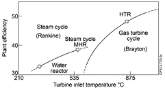
Figure 12. Plant efficiency as function of turbine inlet temperature (source [71]).
Download figure:
Standard image High-resolution image
Coolant circulation and power conversion systems must be both highly safe and reliable, as they communicate between the plasma and the balance of the plant, transporting energy, and possibly tritium and radioactive impurities that must be strictly controlled. Large part of the primary heat transfer system (PHTS) is inside the vacuum vessel and in immediate proximity to the plasma. This has strong implications on the design, materials, maintenance and reliability requirements for such components.
Exploratory power cycle modelling and assessment of technology maturity highlight the water/steam-based Rankine cycle as an appropriate choice for DEMO [72]. For example, cycle simulations with a water-based divertor (<250 °C) and helium-cooled blanket (300–500 °C) indicate water/steam-based Rankine cycles are able to meet the required net plant efficiency target of 25% via a cycle incorporating use of divertor heat, reheat and feed heating. Such a cycle offers substantial operational precedence and low levels of technical risk for key components. Further work is currently underway to assess the most applicable variation of this cycle for use with the WCLL blanket.
The performance benefits, risks and recent precedence for novel cycles such as supercritical carbon dioxide Brayton cycles, are also being assessed to understand the viability of options beyond water/steam-based Rankine cycles. However, it is clear that high temperature options such as helium-based Brayton cycles are not applicable for the current DEMO blankets due to the necessity for primary coolant temperatures well in excess of 500oC in order to meet the net plant efficiency target.
This represents a strong incentive to push supercritical steam Rankine to 550 C and especially to develop 4th generation ferritic-Martensitic steels or ODS, as described in [49].
The proposed pulsed operation of DEMO creates significant challenges for the primary heat transfer system and BoP. Although the thermal cycle and electrical power conversion systems may utilise existing technology, their operation in a pulsed manner will not be straightforward, with the impact of frequent and significant cycling potentially detrimental to the lifetime of key components, such as heat exchangers, turbines and pumps [71]. Few attempts have been made to understand these impactsand the resulting feasibility of pulsed operation. Solutions involving an energy storage system (ESS) to mitigate any issues have been proposed [73]; however, the financial impact could be significant and without a firm understanding of the inherent cycling challenges, it is not possible to justify such a system. [74] simulate the time-variant behaviour of the heat transfer and BoP systems for DEMO, without an ESS, to gain insight into the major technical challenges of pulsed operation and possible mitigation strategies. An operating regime is defined for water such that the primary coolant flows continuously throughout the dwell period while the secondary steam flow is reduced. Simulation results show minimised thermal and pressure transients in the primary circuit, and small thermally induced stresses on the steam turbine rotor. If the turbine can also be kept spinning to minimise mechanical cycling, pulsed operation of a water-cooled DEMO without thermal energy storage may be feasible. The applicability of the operational concept to a helium-cooled DEMO is also worth consideration. The water-cooled concept benefits from a small difference between the inlet and outlet temperatures of the coolant during a pulse, which minimises transients as the temperatures converge during the dwell, and low primary coolant pumping powers (~10 MW), which renders feasible the idea of keeping the pumps running during the dwell. For a helium-cooled blanket, the difference between the inlet temperature (300 °C) and outlet temperature (500 °C) is greater, and the pumping power will be much greater, around 150 MW. Operating a helium-cooled DEMO without an ESS in the same way therefore appears inherently more challenging.
5.5. Materials issues for diagnostic front-end components
Diagnostics will be integrated into DEMO primarily for the purpose of plasma control. Specific material issues are discussed in [75]. The DEMO plasma control system has to provide extremely high accuracy and reliability of plasma operation in compliance with safety requirements, ensure protection against machine damage and optimise DEMO performance [76]. The implementation of diagnostic front end components on DEMO is however facing severe limitations: First, the fraction of openings and voids in the breeding blanket has to be minimized in order to achieve a Tritium breeding rate TBR > 1. Second, diagnostic front-end components will be subject to an extremely harsh environment: strong heat, radiation and particle fluxes fom neutrons, neutral particles and ions in a wide energy range, electromagnetic radiation from the infrared to the gamma range, strong forces, moments and stresses are acting on the components. Since any maintenance on these components would be very time consuming, all vulnerable components may only be installed in well protected locations, e.g. at some distance behind the first wall or blanket. These limitations are pushing towards a scarce diagnostic system with low performance, which however is unfavourable in view of the extreme requirements on control reliability.
In addition to the material embrittlement by displacement damage (dpa) and transmutation (chemical changes, helium production, swelling), a number of specific nuclear radiation effects have been investigated with respect to their impact on ITER diagnostics components [77]: radiation-induced conductivity (RIC), radiation-induced electrical degradation (RIED), radiation-induced thermo-electric sensitivity (RITES) and radiation- and temperature-induced electromotive forces (RIEMF, TIEMF), all of which are modifying the material structure such that the electrical and optical properties of the components are substantially changed.
Plasma radiation measurements with high accuracy in the various regions core plasma, edge plasma, divertor plasma and x-point region, together with a thermographic characterisation of the high heat flux areas of the divertor targets, are crucial to be able to control the plasma radiation level such that the power flow across the separatrix is staying above the H mode threshold, but on the same time the local power fluxes should remain low enough to protect the divertor from overloading. To accomplish the detailed control of radiation via seeding of impurities into the plasma, a good characterisation of the impurity species via spectroscopic measurements is required in all the various plasma regions. For all types of radiation and spectroscopic measurements, individual narrow sightlines with first mirrors located behind the blanket are foreseen as the best approach to combine the required spatial coverage with the need of lifetime optimisation for the first mirrors. Metallic mirrors may also be used for the infrared interferometry/polarimetry foreseen to access the central plasma density profiles. The availability of accurate data on irradiation effects on candidate mirror materials, as well as precise predictions on erosion and deposition effects, are mandatory to be able to optimise the design of these diagnostics towards the DEMO control needs while ensuring a long lifetime avoiding the need for maintenance.
Magnetic coils based and Hall sensors may be employed behind the blanket to measure the magnetic fluxes for the purpose of plasma position and shape control. Here, the changes in conductor and insulator properties, as well as spurious voltages arising from irradation effects, will be the limiting factors for application of these sensors.
For plasma detachment control, the measurement of divertor thermo-currents is foreseen, which requires the electrically insulated mounting of a number of divertor target plates or parts of them. Like for the magnetic sensors, the durability of the ceramic insulators under the conditions of irradiation may be limiting the application on DEMO.
Since the time response of magnetic sensors in retracted positions may be too low for e.g. fast MHD control purposes, microwave diagnostics will get a wider role on DEMO as compared to any existing tokamak. Assuming a large number of individual microwave horn antennae located at various poloidal and toroidal positions, using a number of different frequencies, a good coverage of the core plasma can be obtained with electron cyclotron emission and reflectometric measurements. From the microwave signals, the plasma temperature and density profiles, plasma shape and position and information on all types of instabilities may be deduced. For the implementation on DEMO, metallic horn antennae from a DEMO compatible material with high electrical conductivity (e.g. tungsten) have to be developed and integrated into the blanket front side, connected to metallic waveguides which are linking the front end to the microwave detection units outside the tokamak.
Finally, neutron and gamma diagnostics will employ long straight tube-like access tubes with detectors located well outside the tokamak, so that a detector exchange could be done via remote handling and hence no severe materials issues are expected for these measurements.
6. Concluding remarks
The early demonstration of production of electricity in a demonstration fusion power reactor (DEMO) that produces its own fuel represents the primary objective of the fusion development program in Europe. The approach followed in Europe to achieve this goal is outlined in this paper together with a preliminary description of the design solutions being considered and the R&D strategy required to resolve outstanding challenges that still lie ahead. The DEMO design options outlined in this paper are not intended to represent the only possible design points but rather 'examples' to be used to identify generic design/ material issues that need to be resolved in future fusion reactor systems. ITER is the key facility in this strategy and the DEMO design is expected to benefit largely from the experience that is being gained with the ITER construction. Nevertheless, there are still outstanding gaps that need to be overcome requiring a pragmatic approach especially to evaluate and improve through dedicated physics and technology R&D the readiness of the foreseeable technical solutions. The main technical issues arising from the plasma and nuclear loads and the effects of radiation damage particularly on the structural and heat sink materials of the vessel and in-vessel components are critically discussed in this paper.
The performance and lifetime of structural and PFC materials for in-vessel components is among the foremost considerations for the successful development and deployment of DEMO and future fusion reactor systems. The very demanding operational requirements (e.g. elevated operating temperature, cyclic operation with long hold time, prolonged periods of operation, steep temperature and stress gradients, multi-axial loading, high neutron irradiation damage and a very high production rates of helium and hydrogen as well as corrosion/erosion) that the structural materials will experience in a DEMO and future fusion power plants are beyond today's experience (including ITER and fission reactors). The challenge is on designing, with sufficient margins, improvement of material properties towards increased radiation resistance as well as prediction of failure mechanisms and lifetime under service conditions. A system engineering approach is needed. Incorporating lessons learned from ITER design and construction, together with involvement of industry and exploitation of international collaborations on a number of critical technical aspects is necessary
The need to establish realistic target performance and a development schedule for near-term electricity production tends to favour more conservative technology choices. The readiness of the technical (physics and technology) assumptions that are being made is also expected to be an important factor for the selection of the technical features of the device.
Acknowledgments
This work has been carried out within the framework of the EUROfusion Consortium and has received funding from the EURATOM research and training programme 2014–2018 under grant agreement No 633053. The views and opinions expressed herein do not necessarily reflect those of the European Commission. We are also very grateful to the ASTRID and MYRRHA teams for the advice and observations they have made. The useful discussion with Derek Stork in preparing and reviewing this manuscript is kindly acknowledged.
Footnotes
- 5
Evolutionary design—is an advanced design that achieves improvements over existing designs through small to moderate modifications, with a strong emphasis on maintaining proven design features to minimize technological risks. The development of an evolutionary design requires at most engineering and confirmatory testing.
- 6
Innovative design—is an advanced design which incorporates radical conceptual changes in design approaches or system configuration in comparison with existing practice. Substantial R&D, feasibility tests, and a prototype or demonstration plant are probably required.
- 7
A higher dpa/fpy in the coolant layer compared to the divertor armour is possible, despite the reduced neutron fluxes, because of the different masses of copper and tungsten—the copper atoms will, on average, experience more energetic atomic recoils under neutron irradiation than the much heavier tungsten atoms.
- 8
For clarification, consider the following basic definitions:
- Code is a set of rules and recommendations to assist demonstration of regulatory compliance. The rules typically cover design and analysis, material procurement, fabrication, inspection through operation and asset management, giving consistency to ensure the structural integrity of components through life and are subject to continuous improvement based upon feedback from industrial experience.
- Structural Design Criteria are the body of rules offering a framework for design validation, supported by relevant material specifications and properties; may be found within the broader body of a code or in isolation.
- Standards are a set of technical definitions and guidelines that function as instructions for designers, manufacturers, operators, or users of equipment.
- 9
10 fpy is considered as this gives a 30 year operational life for DEMO at an average 33% load factor.
- 10
Note these simulations do not yet include realistic penetrations (eg. for neutral beam lines of sight.