

Abstract
Objective. We present a combination of a power electronics system and magnetic nanoparticles that enable frequency-multiplexed magnetothermal-neurostimulation with rapid channel switching between three independent channels spanning a wide frequency range. Approach. The electronics system generates alternating magnetic field spanning 50 kHz to 5 MHz in the same coil by combining silicon (Si) and gallium-nitride (GaN) transistors to resolve the high spread of coil impedance and current required throughout the wide bandwidth. The system drives a liquid-cooled field coil via capacitor banks, forming three series resonance channels which are multiplexed using high-voltage contactors. We characterized the system by the output channels' frequencies, field strength, and switching time, as well as the system's overall operation stability. Using different frequency–amplitude combinations of the magnetic field to target specific magnetic nanoparticles with different coercivity, we demonstrate actuation of iron oxide nanoparticles in all three channels, including a novel nanoparticle composition responding to magnetic fields in the megahertz range. Main results. The system achieved the desired target field strengths for three frequency channels, with switching speed between channels on the order of milliseconds. Specific absorption rate measurements and infrared thermal imaging performed with three types of magnetic nanoparticles demonstrated selective heating and validated the system's intended use. Significance. The system uses a hybrid of Si and GaN transistors in bridge configuration instead of conventional amplifier circuit concepts to drive the magnetic field coil and contactors for fast switching between different capacitor banks. Series-resonance circuits ensure a high output quality while keeping the system efficient. This approach could significantly improve the speed and flexibility of frequency-multiplexed nanoparticle actuation, such as magnetogenetic neurostimulation, and thus provide the technical means for selective stimulation below the magnetic field's fundamental spatial focality limits.
Export citation and abstract BibTeX RIS
1. Introduction
Alternating magnetic fields serve a wide range of applications in medicine and biological research. Strong alternating magnetic fields applied to magnetic nanoparticles can generate forces or heat at the location of the nanoparticles at depth within biological tissue. This local heating can be used for hyperthermal cancer treatment [1, 2], genetic transfection [3], protein manipulation [4], or site-specific drug release [5, 6]. When the magnetic nanoparticles are in close proximity or bound to cells expressing temperature-sensitive transient receptor potential channels, neural activity in a genetically targeted population is evoked in a process known as magneto-thermal genetics or magnetogenetics [7–10]. Magnetogenetic neurostimulation could be a breakthrough for minimally invasive neuromodulation, because it benefits from both the transparency of tissue to magnetic fields up to the high megahertz range as well as the nearly unlimited focality and/or selectivity of the stimulation effect due to the localization of the magnetic nanoparticles near sensitive ion channels. In contrast, the stimulation fields formed about 15 millimeters below the skull by conventional transcranial electrical stimulation (TES) and transcranial magnetic stimulation (TMS) have natural focality limits [11, 12] due to the current spread and shunting for TES [13, 14] and the fundamental depth–focality trade-off for TMS [15, 16]. In addition, selective heating of magnetic nanoparticles using various frequency–amplitude combinations of the magnetic field has been achieved via variation of the size and coercivity of magnetic nanoparticles [17, 18]. Thus, multichannel stimulation could allow high differential selectivity even between closely located neural elements.
For multichannel stimulation with frequency-selective nanoparticles, however, the field source needs to be able to generate widely different frequencies at various amplitudes. Also, short turn-on and turn-off times of the field and rapid changes between frequency channels are required for reasonable signaling and driving of network effects. So far, multichannel stimulation has only been demonstrated with two channels in the frequency range of tens to hundreds of kilohertz [17, 18]. To increase the number of channels for magnetogenetics, new magnetic nanoparticles need to be developed to respond to magnetic fields in the megahertz range. This in turn requires high-power electronics that can generate such MHz magnetic fields in addition to the lower frequencies, together spanning a wide frequency range, for characterizing the nanoparticles and heating them in applications. However, most existing methods for generating magnetic fields with sufficient strength are limited to the kilohertz range.
Prior research often uses general-purpose linear amplifiers with power levels of several hundred watts to drive magnetic coils [7, 17, 19]. Despite their relatively wide band and continuously adjustable frequency, these amplifier circuits have limitations in efficiency, power, and frequency [20], and do not have the capability to generate magnetic fields with the aforementioned characteristics. Due to the extremely weak electromagnetic coupling between the magnetic coil and target tissue, powerful sources are typically required to deliver to the coil at least 200 A at relative high frequency. Common power electronics solutions are challenged by such requirements due to significant trade-offs between power and field strength versus the frequency and spatial characteristics of the field [21]. For instance, when the field frequency is changed by a factor of 100 (∼50 kHz to ∼5 MHz here) for good separation between several channels, the necessary voltage likewise increases by a factor of 100 for approximately equal power given the coil's inductive impedance. Although in-vitro characterization of nanoparticles has been performed with low power in the megahertz range (e.g. several MHz to 40 MHz) [7, 22], the use of miniaturized field coils (less than 1 cm diameter) or sample placement within the air gap of a ferrite core significantly limit the spatial extent of the field for application in vivo, where the targets are located outside the coil. Achieving the required field strength at distance and megahertz frequency is challenging for the power electronics because of the need for both high frequency and high power, together with the constraint to use coils that are also suitable for lower frequencies and hence have relatively high impedance and losses in the megahertz range.
Resonance circuits, in which energy oscillates between a coil (L) and a capacitor (C), provide a practical way for producing strong magnetic fields [21]. The power electronics does not have to deliver reactive power to the coil, but only supplies the losses due to the internal resistance, field absorption, and wave emission. Additionally, the majority of the coils' inductive impedance is compensated, so that for series resonance the necessary voltage for the power electronics no longer grows linearly with the frequency. However, the state-of-the-art series-resonant circuit technology has several limitations. First, the output frequency of a resonator is fixed. Second, the wide frequency range of more than six octaves pushes conventional silicon (Si) transistors beyond their limits. At low frequencies, the electronics must drive up to 500 A, requiring high-power silicon transistors. While these high-power silicon transistors serve well for the low frequency (kilohertz) range, they exhibit large parasitics, such as the gate and the drain–source capacitance, and thus cannot operate efficiently in the megahertz range [20].
Considering these challenges, we present a hybrid silicon–gallium-nitride field-effect transistor (FET) circuit with switching modulation and adaptive series resonance. Compared to linear amplifiers, switched circuits deliver poor output quality with regard to distortion and other frequency content, but the resonant configuration serves as a sharp filter and only passes sinusoidal currents. The hybrid configuration with Si and gallium-nitride (GaN) exploits the advantages of each technology while avoiding their drawbacks: Vertical trench Si FETs with their high-current capability but limited speed due to parasitics and slow carrier dynamics deliver power for low to medium frequencies (50 kHz–500 kHz). Lateral GaN-on-Si FETs with their high speed but limited thermal and current capabilities take over at high frequencies (⩾1 MHz). We solve the fixed resonance frequency by implementing multiple sets of capacitors with rapid software-controlled multiplexing in between using high-current high-voltage contactors, which add minimal conduction loss and provide switching times on the order of milliseconds, suitable for most applications. We demonstrate a system with three channels, each separated by a factor of ten in frequency and field strength for the required amplitude–frequency product [21, 23] H0 f⩽ 5 × 10⁹ A m−1 s−1 (see table 1). The wide band of frequencies among the channels encompass the range of existing magnetic nanoparticles with good selectivity [17, 18] and enable the exploration of novel nanoparticles responding preferably to higher frequencies.
Table 1. Design specification of the three channels with nominal value and target range in parentheses.
| Parameter | Units | Channel 1 | Channel 2 | Channel 3 | |||
|---|---|---|---|---|---|---|---|
| Frequency | kHz | 50 | (50–100) | 500 | (380–580) | 5000 | (2000–5000) |
| Magnetic field | kA m−1 | 70 | (50–100) | 10 | (8–12) | 1 | (0.8–1.6) |
| mT | 88 | (63–125) | 13 | (10–15) | 1.3 | (1–2) | |
| Amplitude-frequency | 109 Am−1 s−1 | 3.5 | (3.5–5) | 5 | (3–5) | 5 | (4–5) |
2. Methods
2.1. Electronics, control strategy, and system integration
We employ series L–C oscillation to drive alternating current in a high-flux petri dish coil (Lcoil = 3.14 μH, see section 2.2) to generate the alternating magnetic field. Three capacitor banks are attached to the same coil, with each bank tuned to achieve a single channel frequency. This design allows simple expansion to include additional channels. A hybrid full-bridge circuit generates rectangular voltage output with adjustable duty cycle and frequency controlled by a system-on-chip (SoC) controller. The duty cycle controls the coil current's amplitude (pulse width modulation), and the frequency is tuned to match the resonance frequency of one of the L–C banks to excite it. The series resonance as a sharp notch-filter presents a large impedance to all frequency contents of the rectangular driving voltage except for its fundamental so that a sinusoidal current follows. Once tuned, the driving circuit only needs to operate at a low voltage (here ±36 V peak for the rectangular waveform) and the resonance design shields off the reactive component. Despite the low voltage on the electronics side, the coil and capacitor voltages can reach 1 kV rms. On the other hand, the coil current (up to 500 A rms for Channel 1—Ch 1) must entirely flow through the circuit, requiring proper wiring and cooling design.
Instead of one transistor technology for the entire range of frequencies and currents, two specialized device types, each optimized for a part of the frequency range, work collaboratively for various trade-offs (figure 1): for Channel 3 (Ch 3), the power switches of the circuit need to operate on the order of f ⩾ 2 MHz but only conduct low current (e.g. Icoil ⩽ 10 A rms). Latest high-electron-mobility GaN-type transistors appear to fit this scenario perfectly, due to their lower parasitic capacitance at gate and output, shorter carrier lifetimes, higher critical field strength, and higher charge carrier mobility [24, 25]. In contrast, the operating current of Ch 1 can reach beyond 500 A. Vertical Si power trench FETs are more suitable here due to their large die areas. The electronic circuit is modularized, with each module sharing a similar layout for better scaling. The full-bridge circuit for the 50 kHz channel is implemented with 16 Si FETs (IPT015N10N5, Infineon Technologies AG, Neubiberg, Germany) for each switch due to the peak current demand. At 500 kHz, the controller activates four FETs per switch at a time in a round-robin fashion to reduce the switching loss. As for the MHz channel, the driving voltage is provided by a full bridge with four GaN transistors (GS61008T, GaN Systems, Ottawa, Canada).
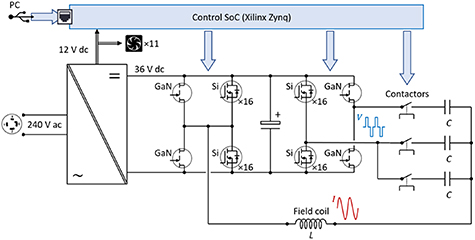
Figure 1. Multiplexed coil driver. Schematic overview of the electronics. The control signals are denoted with blue arrows.
Download figure:
Standard image High-resolution imageWe use contactors to decouple different channels. The contactors (B88269X1090C011, TDK Electronics AG, Munich, Germany) avoid circulating currents between different channels and allow the magnetic coil to be electrically connected to one set of the corresponding series capacitors for each channel at a time. The contactors are driven by lower power FETs (ZVN4210A, Diodes Incorporated, Plano, TX, USA) via a SoC controller. Supplementary table S1 (available online at stacks.iop.org/JNE/19/026015/mmedia) lists the major electronic components and technical specification of the three channels.
The capacitor bank is implemented with polypropylene film capacitors for high voltage, high current, and high frequency applications (Cornell Dubilier Electronics, Liberty, SC, USA and WIMA GmbH & Co. KG, Mannheim, Germany). Quick-change sockets (SparkFun Electronics, Niwot, CO, USA) are used so that capacitors can be switched in and out to tune the frequency of the resonance circuit. As the power electronics' output frequency is limited by the clock frequency (100 MHz) of the SoC, the adjustment in the megahertz range is more granular and the output frequency of Ch 3 might not meet the exact resonance frequency of its L–C circuit using discrete capacitors. Therefore, a variable capacitor (10–100 pF, Sprague Goodman Electronics, Westbury, NY, USA) operates in series with the replaceable film capacitors, which allows the user to tune the circuit to resonate at the discrete frequencies output in the megahertz range and maximize the output current and magnetic field. For Ch 1 and Ch 2, the frequency step size is fine enough. Thus, resonance can be reached by adjusting the output frequency via the user interface. The voltage rating of the resonating capacitors should be high enough to accommodate the peak operating voltage up to 1 kV across the capacitors and inductors.
A SoC with field-programmable gate array (FPGA) and ARM Cortex A9 microcontroller (Xilinx Zynq 7000, sbRIO-9627, National Instrument, Austin, TX, USA) controls the transistor banks and the contactors. The SoC connects to a PC with a graphic user interface (LabVIEW, National Instruments, Austin, TX, USA) through an ethernet–USB adapter, which selects and sets the stimulation channels (pulse duration, interpulse interval, stimulation frequency, and amplitude, etc). The FPGA part of the SoC performs all transistor switching, for which we clocked it at 100 MHz to refine the time resolution so that the driver circuit can hit all necessary frequencies close enough.
The electrical cable of approximately 30 cm length consists of six interleaved high-voltage insulated 12-gauge (American wire gauge) type-8 Litz wires (New England Wires Technologies, Lisbon, NH, USA), with three wires in each direction. The cable is ensheathed in interference-shielding heat-shrink tubing to reduce radio-frequency noise leakage and terminated in compression lugs that connect to the coil.
All electronics components were placed in a standard four-height-unit 19 inch vented rack (Hammond Manufacturing, Guelph, Canada), with the aluminum enclosure acting as shielding to limit RF noise leaking to the nearby equipment. Heat sinks were added on the electronics boards to increase thermal capacity and surface area, and each circuit module had two fans, one above and one below, for cooling. A 12 V AC/DC adapter powers the FPGA and fans and five 36 V 1 kW DC power supplies (Mean Well USA, Fremont, CA, USA) powered the electronics. A layout of the integrated system is shown in figure S1.
2.2. Magnetic stimulation coil
The magnetic field coil (Hi-Flux module, MSI Automation, Wichita, KS, USA) consists of a six-turn solenoidal coil of 5.75 cm inner diameter and 3.8 cm height wound with a 3/16 inch (4.76 mm) diameter copper tube, which allows liquid cooling with water (figure S2). The coil contains a ferrite core (μ = 2300, Ferroxcube 3C90, Eindhoven, Netherland) in a sealed compartment. The coil is located with its cylindrical axis vertically within a nylon panel enclosure on which petri dishes can be placed for microscope imaging. The coil and core were potted in high-temperature epoxy (Devcon, Milpitas, CA). The upper rim of coil windings and ferrite inside the compartment are 3 mm below the surface for placing petri dishes. The coil is electrically connected via two ¼-20'' bolts to the cable, and both the coil and the ferrite compartment are cooled via chilled circulation attached via metal quick-disconnect fittings (CPC Colder, St. Paul, MN, USA). The coil's electrical characteristics were measured in four-wire configuration with a bench LCR/ESR meter (Model 889A, B&K Precision Corporation, USA).
2.3. Testing and measurement set-up
We performed all electrical measurements with a 500 MHz high-bandwidth oscilloscope (Tektronix MDO3054, Beaverton, OR, USA). High-voltage differential probes (Tektronix THDP0100) served to measure the coil voltage, whereas Rogowski current transducers (CWT 60B & CWT MiniHF 1B, Power Electronic Measurement Ltd, Nottingham, UK, for Ch 1 & Ch 2 and Ch 2 & Ch 3, respectively) detected the coil current. To measure the magnetic field generated by the coil, we used a magnetic flux test coil of ten turns by winding 30-gauge magnetic wire around a 3D-printed polylactic acid cylindrical former of 1 cm diameter (Ultimaker B.V., Utrecht, Netherlands). The probe measures the voltage induced by the changing magnetic flux of the alternating magnetic field and the field strength was derived in either the time or frequency domain.
Resonance frequencies for each channel were confirmed by varying the output frequency of the electronics circuit and maximizing the measured coil current/voltage or induced voltage of the magnetic field probe. Once the resonance frequency was recorded, it was not changed any more during operation.
We tested sequential cycling through the three channels with the following settings: Ch 1, 49.9 kHz, 90 mT; Ch 2, 549 kHz, 13.7 mT; Ch 3, 2.5 MHz, 3.9 mT (see results on frequency and amplitude combinations of the channels). The channels were cycled in the order from lowest to highest frequency with equal pulse duration of 3 s and two inter-pulse intervals of 17 s and 7 s were tested, corresponding to a duty cycle and coil current of 15% with 88 A and 30% with 125 A, respectively. Temperatures of the coil, cable, and electrical and electronics components within the rack were measured using a handheld infrared thermometer (Fluke Corporation, Everett, WA, USA).
Data analysis was performed in MATLAB (R2019b, The MathWorks, Natick, MA, USA). To calculate the magnetic field, the induced voltage was detrended to remove any DC offset, filtered above 50 MHz, and integrated.
2.4. Nanoparticle synthesis and measurement
Three types of magnetic nanoparticles with different coercivity were developed to form three magnetothermal channels. Our 15 nm cobalt-doped iron oxide (Co0.65Fe2.35O4) nanoparticles generate a large amount of heat in a low-frequency high-amplitude magnetic field (Ch 1), 19 nm iron oxide (Fe3O4) nanoparticles in a medium-frequency medium-amplitude field (Ch 2), and 10 nm manganese-doped iron oxide (Mn0.57Fe2.43O4) nanoparticles in a high-frequency low-amplitude field (Ch 3). The synthesis, coating, and functionalization of these nanoparticles followed previous methods [18, 26]. Briefly, magnetite nanocrystals of 4 nm diameter were first synthesized by thermal decomposition of iron acetylacetonate in a mixture of oleic acid and benzyl ether and increased to 15 nm diameter size by controllable seed-mediated growth in a mixture of iron acetylacetonate (Fe(C5H7O2)3), oleic acid, and benzyl ether. Then, the nanocrystals were coated with a copolymers of phospholipids and polyethylene glycol (DSPE-PEG2K) using a dual-solvent exchange method [27]. The cobalt-doped nanoparticles were synthesized from multiple seed-mediated growth reactions through thermal decomposition with 5 nm iron oxide cores in 2 mmol CoCl2, 4 mmol Fe(C5H7O2)3, 25 mmol oleic acid, using 60 ml benzyl ether as a solvent. Manganese-doped seeds of 7 nm size were synthesized with a mixture of 5 mmol MnCl2, 10 mmol Fe(C5H7O2)3, 50 mmol 1,2-tetradecanediol, 60 mmol oleic acid, 60 mmol oleylamine and 60 ml benzyl ether. The seeds were then grown to 10 nm with a seed-mediated growth procedure. The reacting solution was heated to 120 °C for 30 min under a constant argon flow, then to 200 °C for 2 h and finally to reflux at 300 °C for 30 min. The product was purified through several acetone washes. The nanoparticle sizes were determined by high contrast transmission electron microscopy (TEM). Nanoparticles were then coated with DSPE-PEG2K by mixing the nanoparticles with PEG and adding dimethyl sulfoxide (DMSO) . The reaction was then evaporated and transferred to water by a drop-wise addition of water and removal of the remaining DMSO by was done by centrifugation and ultracentrifugation.
TEM, superconducting quantum interference device (SQUID), and power x-ray diffraction (XRD) measurements were performed to quantify the size distribution, magnetic properties, and the crystal structure of the magnetite nanocrystals, respectively. The hydrodynamic size of conjugated nanoparticles was subsequently examined by dynamic light scattering. The samples for TEM measurements were prepared by diluting the samples and placing them in carbon-film grids. XRD samples were prepared by drying the nanoparticles under an argon flow and then pulverizing the resulting powder. SQUID measurements were performed with coated samples by fixing the nanoparticles with calcium hemisulfate and enclosing them within a capsule to prevent movement. Doping percentages were determined by inductively coupled plasma mass spectrometry and comparing the samples to the corresponding standard curves of iron, cobalt, and manganese.
The nanoparticle samples were placed on the surface of the coil and the heating was measured using an infrared thermal probe (Luxtron 812 and STF-2 M probe, Lumasense, Santa Clara, CA, USA). The specific absorption rate (SAR) is calculated as
where  is the specific heat capacity of the media (4180 J kg−1 K−1),
  is the temperature change during stimulation averaged over three stimulations,
  is the stimulation time, and
  is sample density measured by total metal concentration. The undoped, Co-doped, and Mn-doped iron oxide nanoparticles were recorded at 4.33 mgmetal ml−1, 9.58 mgmetal ml−1, and 28.18 mgmetal ml−1, respectively. Thermal images were recorded with an infrared camera (FLIR A700, FLIR, Wilsonville, OR, USA).
3. Results
3.1. Multiplexed coil driver
We characterized the power electronic system driving a high-flux coil to determine whether their performances meet the design goals for heating the nanoparticles. A relative uniform distribution of magnetic field over the central 1 cm region within the petri dish chamber of the coil (figures S2 and S3) ensures that several nanoparticle samples can be exposed to the required field strength when placed above the coil.
While the software ensures hitting the resonant frequencies, the reconfigurable capacitor arrays allow further adjustment of the resonant frequencies. Ch 1 resonates at 49.7 kHz and 61.5 kHz with 2 µF and 3 μF capacitors, respectively. Ch 2's output offers 46 frequencies in the 380–580 kHz frequency range as allowed by the system's clock, and the system was characterized with approximately 25 kHz steps between 400 and 575 kHz. Ch 3 had 15 frequencies within the 2–5 MHz range allowable by the system's clock. The output frequency for each channel can be adjusted using the capacitor combinations in table S2.
The measured magnetic field amplitude (figure 2) shows that the target field strength can be achieved for each channel. However, due to the higher impedance (figure S4) and losses with increased frequency, the achievable magnetic field decreases for higher frequencies and the envisioned target of 1.25 mT was only achieved for frequencies up to ∼4 MHz.
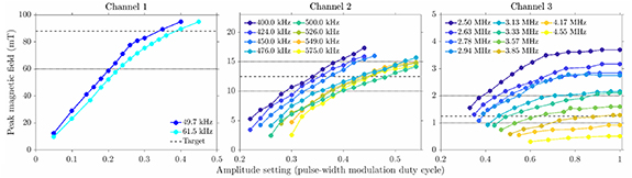
Figure 2. Magnetic field output characteristics of the three channels. The amplitude setting determines the pulse-width modulation of the control voltage on the gates of the transistors. The dashed line shows the nominal target field strength for each channel, with the dotted lines indicating the upper (for Ch 2 and Ch 3 channel only) and lower ranges of the target.
Download figure:
Standard image High-resolution imageAfter the transistors start switching, the L–C circuit begins oscillation with increasing amplitude until reaching steady state. The envelope of this transient can be fitted with an exponential rise and decay at the beginning and end of the stimulation pulse, with time constant inversely proportional to the frequency. Ch 1's time constant was approximately 0.2 ms, requiring about 1 ms to reach steady state or for the oscillation to stop (figure 3(A)); for Ch 2 and Ch 3, the transient's durations were 10- and 100-times shorter, respectively, and therefore negligible compared to the minimum pulse duration anticipated (10 ms). Within each channel, the pulse can be turned on and off with sub-millisecond speed. Between channels, the switching was slower for the contactors to close or open. Also, for safety reasons, a short delay was inserted in the control program when switching between different channels to avoid the high current from one channel and voltage from one capacitor bank carrying over to another one. The switching between channels can be achieved as fast as 1 ms (figure 3(B)).
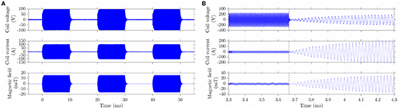
Figure 3. Time of oscillation onset and channel switching time. The coil voltage, current, and magnetic field 3 mm above the center of the coil. (A) Ch 1 switching on and off with 10 ms pulse duration and 10 ms interpulse intervals. (B) Switching from Ch 2 to Ch 1, dashed vertical line indicating switch time.
Download figure:
Standard image High-resolution imageCh 1 and Ch 2 are thermally limited by temperature rise in the Si transistors, the series AC capacitors, the cable and the coil, and may run single pulses up to 10 s and 30 s duration for the presented current levels, respectively. Ch 3 can achieve continuous operation. To test the stability of the system, a pulse train cycling through the three channels was output with equal pulse duration and interpulse intervals at two different duty cycles. The system was able to continuously operate for two hours, with the temperature reaching a steady cycle around 20 min. All components operated well within their specifications and, besides the cable, had moderate temperature (figure S5). As a potential bottleneck of thermal performance, the cable could be made thicker to reduce power losses and heating.
3.2. Nanoparticles heating and channel selectivity
The heating of the three types of nanoparticles was measured over 3 s or 15 s magnetic field stimulation in all three channels, and their specific absorption rates are calculated (figure 4 and table S3). When stimulation time is limited to 3 s for Ch 1 and 15 s for Ch 2 and 3, the maximum temperature change showed a selectivity of ∼9× for 15 nm Cobalt doped nanoparticles in Ch 1, ∼2.3× for 19 nm iron-oxide nanoparticles in Ch 2, and ∼3.7× for 10 nm Mn-doped nanoparticles in Ch 3, thus indicating three distinct channels available for magnetothermal heating. By adjusting the concentration of the nanoparticles and the corresponding stimulation time duration, three samples within the same magnetic field could be separately activated (figure 5).
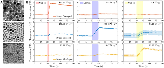
Figure 4. Nanoparticles and their thermal response. (A) Transmission electron microscopy of iron oxide nanoparticles, from top to bottom: 15 nm cobalt-doped, 19 undoped, and 10 nm Mn-doped. (B) Responses of 15 nm cobalt-doped iron oxide nanoparticles (red traces, top row), 19 nm iron oxide nanoparticles (blue, middle row), and 10 nm manganese-doped iron oxide nanoparticles (yellow, bottom row) when exposed to a magnetic field of Ch 1 (left column, 49.9 kHz; 80 mT), Ch 2 (center column, 555 kHz; 12 mT), or Ch 3 (right column, 2.227 MHz, 3.8 mT).
Download figure:
Standard image High-resolution image
Figure 5. Channel selectivity. Thermal imaging recorded with an infrared camera of 10 µl drops of each sample at concentrations adjusted to generate similar amounts of total heat. Channel 1 shows selective heating of 15 nm Co-doped iron oxide (∼8 mg ml−1), whereas channel 2 targets 19 nm iron oxide (∼3 mg ml−1) and channel 3 10 nm Mn-doped iron oxide (∼22 mg ml−1).
Download figure:
Standard image High-resolution image
4. Discussion
In summary, we report the first high-bandwidth multichannel power electronics system and magnetic nanoparticles for frequency-multiplexed magnetogenetic neurostimulation with three distinct channels. The system spanned a wide frequency range from low kilohertz to megahertz, can be flexibly configured and programmed, and showed millisecond switching speed between channels as well as thermal stability for hour-long operation. We demonstrated selective heating of magnetic particles in all three channels by using a combination of the duration of each channel's stimulation time and the concentration of the nanoparticles. This system enables experimental studies of magnetogenetic neurostimulation with improved selectively, speed, and flexibility. For instance, we used the system and nanoparticles presented in this study to demonstrate sub-second behavioral responses including wing extension and side-to-side movement in Drosophila melanogaster expressing rate-sensitive thermoreceptors [18]. Remote and focal activation of the cortex in animal or human subjects could be achieved by driving smaller coils placed on the scalp using the multichannel power electronics system and activating nanoparticles locally-delivered through the blood–brain barrier using focused ultrasound [28, 29].
In this study, the key innovation for the power electronic system is to adopt a hybrid approach with two types of transistors, optimized for the different frequency and current levels required, and high voltage contactors for switching channels with millisecond speed. The Si transistors provide high current at the lower-frequency ranges, whereas the GaN transistors covered the highest frequencies, where the current magnitude is lower. The system can select from various capacitor banks and temporarily connect them to the coil via contactors. In contrast to the transistors in the power electronic circuit, the contactors must both conduct high currents when closed—particularly for the low-frequency range—and block high voltage when opened. The switching speed of channels is primarily determined by the mechanical speed of the contactors. Such a combination is currently challenging in electronics. The achieved millisecond channel switching is sufficient for current magnetogenetic applications that typically have response times on the order of at least hundreds of milliseconds and up to several seconds [7–9]. Unlike several conventional systems in which the capacitor bank is located next to the coil and sometimes integrated with it, our system combines the capacitor banks with the power electronics unit and connects them to the coil via a flexible and long cable. This separation of source and magnetic coil enables the placement of the coil under a microscope. Furthermore, it allows better combination with other units of typical magnetogenetic systems, such as temperature and humidity control as well as perfusion while having the power system placed far from the imaging set-up, reducing electronic noise and vibration. Litz wire reduces high-frequency losses, and the cable's terminal design is capable of interfacing with other available coils, for example the commercial nanoTherics magneThermTM coil [30], which we tested during the prototyping phase.
The system's long-term operation was mostly restricted due to the thermal limitations of several components. For single pulses under low repetition rate, the limiting factors determining the maximum pulse duration for Ch 1 and Ch 2 were the Si power electronics and the AC capacitors, whereas the coil does not experience significant heating. On the other hand, the MHz channel can run continuously. In addition to the Ch 1 and Ch 2 electronic components, repetitive pulsing needs to consider the cable and coil to avoid thermal stimulation of the neuronal targets.
This study demonstrates a proof of concept for three-channel magnetogenetics. The approach is to modify the magnetic anisotropy of single-domain super-paramagnetic nanoparticles via doping and adjust the frequency and field strength of AMF stimulations to pair selectively with the anisotropy of those particles. Selectivity and actuation strength can be improved and potentially further multiplexed with the inclusion of multicore nanoclusters which enable higher heating rates [18, 31]. For the MHz channel, the anisotropy is lowered by the inclusion of manganese in the crystal structure. Further optimization of doping concentrations and tuning of the magnetic field may improve selectivity and allow for more channels in the future.
The system scales well and allows modular expansion of capacitor banks and the transistor circuits to increase the current capabilities as well as the number of channels. The GaN transistors readily allow driving frequencies above 50 MHz. Thus, this system in combination with a coil design optimized for higher frequency can help find magnetic nanoparticles and proteins for higher frequency ranges to further increase multiplexing capabilities.
5. Conclusions
We successfully developed a multi-channel power electronics system capable of generating alternating magnetic field for multiplexed magnetogenetic neurostimulation and used it to drive a commercially available magnetic field-generation coil. The system achieved the desired magnetic field amplitudes for each frequency channel and showed millisecond switching speed between channels as well as thermal stability for hour-long operation. We demonstrated the system's application using a combination of specific absorption rate measurement of magnetic nanoparticles across all three frequency channels and the duration of each channel stimulation time.
Acknowledgments
This research was developed with funding from the Defense Advanced Research Projects Agency (DARPA) of the United States of America, Contract No. N66001-19-C-4020. The presented views, opinions and/or findings are those of the authors and should not be interpreted as representing the official views or policies of the Department of Defense or the USA Government.
Data availability statement
The data that support the findings of this study are available upon reasonable request from the authors.
Author contribution
B W and Z L developed and characterized the electronics system. Z L developed the control software. C E S and D T H characterized the magnetic nanoparticles. D T H and Q Z synthesized the nanoparticles. J T R, B G, A V P, and S M G conceived, supervised, and secured funding and resources for the study. B W performed data visualization and took the lead writing the manuscript, with inputs from Z L, C E S, D T H, J T R, A V P, and S M G. All authors reviewed, commented on, and approved the final version of the manuscript.
The authors thank Dr Zhiyong Zeng, Dr Lari M Koponen, and Rena Hamdan for helpful discussion and technical support. 3D printing was performed in the Innovation Co-Lab of Duke University.
Conflict of interest
The authors declare no competing interests.