
Abstract
Objective. Electrical stimulation of the peripheral nervous system (PNS) can treat various diseases and disorders, including the healing process after nerve injury. A major challenge when designing electrodes for PNS stimulation is the mechanical mismatch between the nerve and the device, which can lead to non-conformal contact, tissue damage and inefficient stimulation due to current leakage. Soft and stretchable cuff electrodes promise to tackle these challenges but often have limited performance and rely on unconventional materials. The aim of this study is to develop a high performance soft and stretchable cuff electrode based on inert materials for low-voltage nerve stimulation. Approach. We developed 50 µm thick stretchable cuff electrodes based on silicone rubber, gold nanowire conductors and platinum coated nanowire electrodes. The electrode performance was characterized under strain cycling to assess the durability of the electrodes. The stimulation capability of the cuff electrodes was evaluated in an in vivo sciatic nerve rat model by measuring the electromyography response to various stimulation pulses. Main results. The stretchable cuff electrodes showed excellent stability for 50% strain cycling and one million stimulation pulses. Saturated homogeneous stimulation of the sciatic nerve was achieved at only 200 mV due to the excellent conformability of the electrodes, the low conductor resistance (0.3 Ohm sq−1), and the low electrode impedance. Significance. The developed stretchable cuff electrode combines favourable mechanical properties and good electrode performance with inert and stable materials, making it ideal for low power supply applications within bioelectronic medicine.
Export citation and abstract BibTeX RIS

Original content from this work may be used under the terms of the Creative Commons Attribution 4.0 license. Any further distribution of this work must maintain attribution to the author(s) and the title of the work, journal citation and DOI.
1. Introduction
Bioelectronic medicine [1–3] can be used as a treatment modality in various diseases and disorders by applying electrical stimulation to the central [4] or peripheral nervous system (PNS) [5–7]. The nerves in the PNS consist of interchanging fascicles wrapped in perineurium and enclosed by a soft and stretchable epineurium [8, 9], which ensures that the nerves can withstand ordinarily bodily motions without harm. If a nerve gets injured, the neurons lose their connection to the target tissues, resulting in loss of muscle function and sensibility in the affected area. Severed nerves are treated by suturing the epineurium of the separated nerve ends together with the hope that the nerve fascicles grow back correctly. Bioelectronic medicine has been successfully employed to promote the regeneration of severed nerves, with one example being the application of electrical pulses to the proximal end of a rat femoral nerve transection during surgery, which led to an acceleration of the axonal nerve regeneration as well as to an increase in preferential muscle reinnervation [10]. Electrical stimulation of the PNS can be performed with various stimulation devices, such as hook- and cuff electrodes. Cuff electrodes can be wrapped around peripheral nerves [11, 12] and are well established within the biomedical industry. When a sufficiently high voltage (above the stimulation threshold) is applied between two electrodes in proximity of the nerve, action potentials are evoked in the nerve fibres. The evoked action potentials propagate along the nerve fibres, which in the case of motor fibres lead to muscular activity that can be recorded visually by monitoring muscle movement [13], or electrically via electromyography (EMG) [14]. Common commercial cuff electrodes incorporate rigid electrodes with a high Young's modulus, leading to a large mechanical mismatch between the electrodes and the soft nerve tissue, which can result in a strong immune response and nerve damage from motions [12, 15, 16]. Furthermore, stiff and thick cuff electrodes typically leave some spacing to the nerve due to their rigid nature, which cause current leakage around the nerve. Contrary, a close conformal electrode minimizes leakage current and thereby improves stimulation threshold, stimulation specificity and signal recording quality [17]. A high stimulation voltage can induce tissue damage around the electrodes as well as damage the electrodes over time [18]. Lower stimulation voltages are also beneficial from an energy consumption perspective, as many cuff electrodes are meant to be implanted chronically and therefore operate under limited energy supply (batteries, wireless energy transfer) [19]. Many researchers have acknowledged these problems and developed thin and flexible cuff electrodes based on polymeric substrates of parylene-C [20–23] and polyimide [24–27]. These flexible devices enable better conformability to the nerve, which results in lower stimulation thresholds as most of the current goes into the nerve.
Although flexible cuff electrodes can establish conformal contact to nerves, they cannot follow the natural bodily motions of the nerves which includes bending and stretching [28]. The Young's modulus of a flexible cuff electrode is typically in the GPa range, which is more than three orders of magnitude higher than reported values for peripheral nerves (typically 40 kPa–20 MPa, nerves are however heterogeneous anisotropic structures of a hyperelastic nature) [7, 29, 30]. This means that a flexible cuff will not deform along with the nerve, thereby potentially inducing tissue damage by for example kinking the nerve at the edge of the cuff [31]. Recently, significant efforts have gone into the development of stretchable bioelectronics [32, 33], and these methods have also been applied towards the development of softer and stretchable cuff electrodes that can deform along with the nerve itself. Decataldo et al used microcracked gold tracks on polydimethylsiloxane (PDMS) to record renal sympathetic nerve activity after 14 d of implantation [34]. To reduce the impedance of their devices, Decataldo et al coated the electrode sites with a poly(3,4-ethylenedioxythiophene) polystyrene sulfonate (PEDOT:PSS) based hydrogel. Liu et al developed soft cuff electrodes based on a PEDOT:PSS hydrogel, which was encapsulated by a photopatternable elastomer [35]. The device could be stretched up to 20%, exhibited a low Young's modulus of 30 kPa, and was used to stimulate the sciatic nerve of rats. In a modified version of this device, a PEDOT:PSS based conductor with glycerol was embedded in a viscoplastic polymer, which showed an increased, although irreversible, stretchability of up to 100% without loss of function. This device could elongate with the growing nerve in chronic implantation and evoke compound action potentials at low stimulation voltages [31]. Stretchable carbon nanotube-PDMS composites [36] and stretchable PEDOT:PSS-polyurethane based cuff electrodes [37] have also been reported for PNS interfacing recently. The above examples demonstrate the potential benefits of soft and stretchable cuff electrodes for nerve interfacing. Electrical stimulation of nerves often requires currents in the 0.1–1 mA, thus, to limit the Ohmic losses and to minimize the applied voltage, it is important that the interconnects and electrodes have low enough impedance. This is a challenge for stretchable interconnects as the sheet resistance of microcracked gold and PEDOT hydrogels are in the order of 10 Ohm sq−1 and ≫100 Ohm sq−1, respectively. Another drawback with PEDOT hydrogels and novel elastomer materials is that they have not been evaluated for long-term clinical applications, while gold, platinum and silicones are well known for their feasibility in bioelectronic implants [7, 19, 38, 39].
To combine high performance with suitable biocompatible materials, here we report on a soft elastically stretchable cuff electrode based on gold, platinum, and PDMS. The device comprises interconnects of gold coated TiO2 nanowires (AuNWs) embedded in PDMS, with an initial sheet resistance of 0.3 Ohm sq−1 and excellent cyclability up to 50% strain. The electrodes were formed by electroplating a thin layer of platinum on top of partially exposed AuNWs and they showed excellent stability for one million monophasic voltage pulses. The cuff electrodes were made of ≈50 µm thick PDMS exhibiting a low Young's modulus of 800 kPa, which ensured a conformal contact between the nerve and the electrode. The device was designed, with the aid of a computational model, to evoke action potentials across the complete cross section of the peripheral nerve, which is preferential for nerve regeneration applications where the aim is to uniformly stimulate all fascicles within the injured nerve. In a rat sciatic nerve model, we were able to evoke major simultaneous activity in the soleus and the tibialis anterior muscle upon applying low voltage monophasic stimulation pulses of 200 mV (94 µA) for 500 µs and evoked minor EMG signals with voltages as low as 50 mV. This demonstrates how the combination of conformal electrode contact, low resistance interconnects, and low impedance electrodes, can result in minimal voltage loss during stimulation and therefore an optimal voltage stimulation threshold of the nerve. Our stretchable cuff electrode thus constitutes a promising candidate for low-power wireless chronic applications due to its material-based biocompatibility, softness, and elastic stretchability.
2. Methods
2.1. Device fabrication
A suspension of gold nanowires (≈300 nm diameter, 3–20 µm length) was prepared according to a previously reported method [40, 41]. In short, auric chloride solution was reduced by hydroxylamine onto poly(vinylpyrrolidone) stabilized TiO2-NWs (Novarials, Novawire-TiO-100-RD, diameter ≈100 nm, length <20 µm, 0.72 mg), leading to gold coated TiO2-NWs (AuNW, diameter ≈300 nm). Figure 1(a) depicts the further fabrication process of the stretchable cuff electrodes. A wax pattern for three devices (area 110 mm2) was printed on a poly(vinylidene difluoride) filter membrane (Merck-Millipore, 0.2 µm pore size) and 3.3 ml of the AuNW suspension was filtered through, resulting in an approximately 4 µm thick AuNWs film deposited on top of the filter membrane (filtration patterning [42]). Polydimethylsiloxane (PDMS, Sylgard 184, Dow Corning, 10:1) was spin coated at 1800 rpm for 30 s on a 2 inch silanized (Trichloro(1H,1H,2H,2H-perfluorooctyl) silane) glass wafer and semi-cured on a hotplate at 70 °C for 10 min until it turned solid but remained sticky. The patterned AuNWs were transferred to the semi-cured PDMS in a hot-press at 200 N force and 75 °C for 20 min. The filter membrane was peeled off the PDMS after wetting with deionised water. The patterned AuNW layer remained on the PDMS and was subsequently partially filled by spin-coating a heptane:PDMS solution (16:1 w w−1) at 6000 rpm for 60 s and cured for 10 min at 80 °C. Additional PDMS was spin-coated at 6000 rpm for 60 s to form an encapsulation layer (≈10 µm) while the contact and electrode sites (6.3 mm long) were protected by pieces of foil (poly(ethylene naphthalate), Teonex, 25 µm thick) that were removed before the final curing step at 80 °C for 4 h, see figure 1(a). The resulting stretchable cuff electrode consisted of two embedded AuNW conductor paths of 700 µm width and 25 mm in length with a spacing of 3 mm in between. The dimensions were chosen to be optimal for complete stimulation of a rat sciatic nerve of 2 mm in diameter, with the overall device dimension being about 1 cm wide and 50 µm thick (60 µm at the conductors).
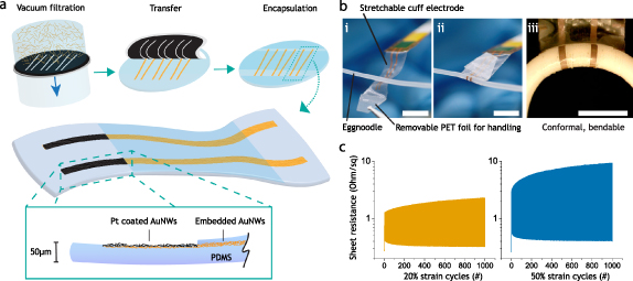
Figure 1. Stretchable cuff electrode. (a) Fabrication via gold nanowire (AuNW) filtration on masked filter membrane, transfer to 50 µm thick spin coated PDMS film, subsequent encapsulation with 10 µm PDMS, and platinum coating of the exposed AuNWs by Pt-electroplating. (b) Stretchable cuff electrode wrapped around an egg noodle exhibiting close conformability and no kinking when bent. Scalebars (i) and (ii) 1 cm, (iii) 5 mm. (c) Strain cycling of AuNWs embedded in PDMS showing sheet resistance over 1000 cycles.
Download figure:
Standard image High-resolution image2.2. Electromechanical characterization
Test samples with 500 µm wide and 20 mm long AuNW conductor paths with contact pads on both ends (42 squares in total) and PDMS layers of similar thickness as the cuff electrodes (50 µm substrate, ≈4 µm AuNWs and 10 µm encapsulation) were fabricated. Strain cycle experiments were performed with a motorized linear stage (X-LSQ300A-E01, Zaber) and the test samples were stretched to 20% and 50%, respectively, for 1000 cycles with a velocity of 2 mm s−1 and a rest time of 1 s. The electrical resistance was simultaneously measured by a Keithley 2701 digital millimetre. Representative data of the strain test samples is shown in figure 1(c). Micrograph pictures were taken before and after strain cycling in relaxed and stretched state with backlight illumination, see figure S1 (available online at stacks.iop.org/JNE/18/045007/mmedia). To determine the device's Young's modulus, cuff electrodes were cut out at the electrode sites (6.3 mm width) and strained along the nerve direction to 10%, 20% and 50% in a motorized linear stage (X-LSQ300A-E01, Zaber, velocity 0.1 mm s−1) while the force was measured with a force gauge (Mark-10 M5-2), see figure S2. The Young's modulus was calculated from the resulting force at 10% strain.
2.3. Electrode preparation and characterization
The AuNWs at the electrode sites were partially exposed by reactive ion etching (RIE) for 10 s (250 W, O2:CF4 1:2 ratio, 100 mTorr). The devices were cut out, peeled from the substrate and connected to a flexible flat cable (FFC, 1 mm pitch, six-ways, Wurth E328849) by applying silver epoxy (MG Chemicals, 8330 S) in between the contacts and cured for 1 h at 95 °C under 150 N force. Kapton tape was taped around the device-FFC interconnection to mediate applied stress during handling. Electrochemical experiments were performed on the devices in a three-electrode cell setup (Platinum gauze counter, Alfa Aesar; Ag/AgCl pellet reference, Warner Instruments E210) with a Gamry Potentiostat 1010E. Electrochemical impedance spectroscopy (EIS, 100 kHz–1 Hz, 50 mV) was performed before and after each process step in phosphate buffered saline solution (PBS, 0.01 M, Sigma Aldrich, P4417) [43]. Cyclic Voltammetry (CV, −1–0,6 V, six cycles, 100 mV s−1) was conducted in PBS to clean the AuNWs electrodes, upon which a thin platinum black layer was electroplated by chronoamperometric pulsing (20 Hz, 10% duty cycle, −1.5 V, 90 s) in a chloroplatinic acid solution (0.8% in H2O, Sigma Aldrich). Strain stability tests were conducted by subjecting the electrodes to 20% and 50% strain consecutively, in a motorized linear stage (X-LSQ300A-E01, Zaber, velocity 2 mm s−1, rest time 1 s) for 1000 cycles. Pulsing stability tests were conducted with a similar protocol as for the in vivo experiments by subjecting the electrodes to 106 monophasic voltage pulses (500 µs, 20 Hz, in PBS, 2 kOhm resistor in series to simulate nerve resistance) of 400 and 800 mV consecutively [43]. After each stability test, EIS (100 kHz–1 Hz, 50 mV) and CV (−0.6–0.6 V, six cycles, 100 mV s−1) was performed consecutively in PBS. Scanning electron microscopy images (SEM, ZEISS Sigma 500 Gemini) and energy dispersive x-ray spectroscopy maps (EDX, BRUKER) were taken of the electrodes before and after RIE, as well as after Pt coating and strain cycling, see figures 2(a)–(d).
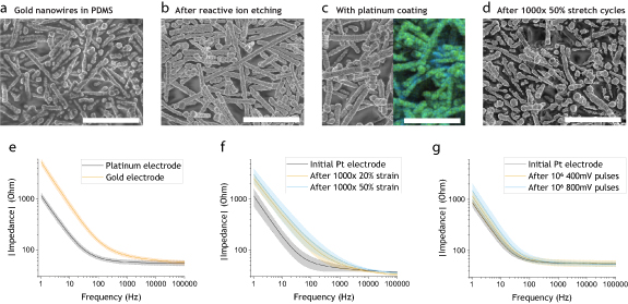
Figure 2. Electrode characterization. (a)–(d) SEM images of the electrodes, scale bars (a)–(d) 5 µm. (a) Partially embedded AuNWs in PDMS. (b) Exposed AuNWs after 10 s RIE. (c) Pt coated AuNWs, inset of EDX mapping showing Pt in green over gold signal in blue. (d) Pt coated electrode after 1000 strain cycles to 50%. (e)–(g) Electrode impedance spectrum (100 kHz–1 Hz, 50 mV), area = 8.8 mm2. (e) Gold electrodes after RIE vs Pt coated electrodes, mean ± sd shown (n = 8). (f) Pt electrodes after 1000 strain cycles to 20% and 50%, respectively. mean ± sd shown (n = 3). (g) Pt electrodes after one million 20 Hz cycles of 500 µs long monophasic voltage pulses of 400 and 800 mV, respectively. mean ± sd shown (n = 3).
Download figure:
Standard image High-resolution image2.4. Numerical simulations
Simulations were performed in COMSOL Multiphysics 5.4 software using the electric currents module to calculate potential and current distributions in conducting media. The model of the nerve and the cuff electrode was implemented in a 2D axisymmetric geometry with the symmetry axis along the length direction of the nerve, see figure 3(e). The nerve model consisted of a single fascicle of endoneurium (r = 740 µm) encapsulated in perineurium (r = 25 µm) and epineurium (35 µm), with a saline layer of 76.5 µm between the nerve and the cuff. The conductivities were adopted from Zariffa et al for endoneurium (0.571 S m−1 along z, 0.0826 S m−1 along r, θ), epineurium (0.0826 S m−1), perineurium (0.0021 S m−1) and saline (2 S m−1) [44]. The areal capacitance of the perineurium was set to 0.39 µF cm−2 which is in line with the range provided by Weerasuriya et al [45]. The electrodes were implemented as highly conductive regions with a surface capacitance set to 100 µF cm−2 to fit the experimental data. Time dependent simulations were performed with identical voltage pulses as in the experimental data. To assess the effect of leakage currents, additional simulations were performed with a saline layer of varying thickness in between the cuff and the nerve, see figure S3.
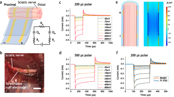
Figure 3. In vivo electrical characterization. (a) Schematic of the stretchable cuff around the sciatic nerve with a simplified circuit model thereof, containing resistances of the AuNW conductors (Rc), constant phase element (QEl) at the electrode interface as well as the resistance of the nerve (RN). (b) Photograph of the stretchable cuff wrapped around the sciatic nerve, scalebar 3 mm. (c) Averaged current response of 200 µs monophasic voltage pulses in vivo. (d) Averaged current response of 500 µs monophasic voltage pulses in vivo. (e) Schematic of cross section of the nerve wrapped with a stretchable cuff electrode and simulated current density for a 200 mV pulse within the nerve (z-component of current density shown in colour, 100 µs into the pulse). (f) Comparison of computational model with experimental data for 200 µs voltage pulses of varying voltages in vivo.
Download figure:
Standard image High-resolution image2.5. In vivo rat sciatic nerve stimulation
Male Sprague Dawley rats (approximately 350 g) were used in the experiments. The rats were anesthetized with a mixture of Isoflurane (Baxter, Deerfield IL, USA) and oxygen, and then placed in a prone position on a heating pad. Anaesthesia was kept constant with isoflurane over a face mask. The hair over the gluteal area on the left side was shaved and cleaned for aseptic procedures. The skin was longitudinally incised over the femoral line at a length of approximately 3 cm. The sciatic nerve was identified through blunt dissection by gently creating a surgical cleavage between the gluteal muscles. Both the sciatic nerve, as well as its division into the tibial and peroneal nerve branches were identified. The stretchable cuff electrode was placed proximal to the division of all muscle branches, where the nerve is approximately 1.6 mm in diameter, see figure 3(b). The stretchable cuff electrodes (n = 5) were connected via a custom made FFC connector to a Gamry Potentiostat 1010E. Cathodic monophasic chronoamperometric pulses were applied from the distal to the proximal electrode with varying frequency (2, 20 Hz), pulse lengths (200, 500 µs) and voltages (50, 75, 100, 150, 200, 400, 600, 800 mV) and the device specific current response was recorded. Two EMG electrodes were placed distal to the nerve in each of the soleus and anterior tibial muscles, and one electrode as ground in the musculature of the back. The EMG electrodes were connected to an IX-BIO-SA biopotential amplifier (iWorx Systems, Inc., 10 kHz sampling rate) which recorded the EMG signals during the experiment. After the experiment, the rats were euthanized without regaining consciousness by immersing them in a closed container containing carbon dioxide. To ensure that the animals were dead, they were thoracotomized. The recorded EMG data from consecutive 2 Hz pulses (n = 4) was integrated and averaged with a custom MatLab script (Mathworks) while excluding EMG recordings with extreme spikes that occurred probably due to static charging of the un-shielded EMG cables. The resulting averaged area values for varying voltages and pulse lengths were then normalized to the maximum value of each EMG recording (stimulation saturation) and the normalized values of each applied voltage (figures 4(e) and (f)) and corresponding current were plotted.

Figure 4. In vivo EMG. (a) Photograph (scalebar 1 cm) and (b) schematic of experiment setup with stretchable cuff wrapped around rat sciatic nerve, and EMG electrodes placed in soleus and anterior tibial muscles. (c) and (d) Representative averaged evoked EMG signal in the soleus muscle for different stimulation voltage pulses of 200 and 500 µs, respectively. (e) and (f) Averaged area of EMG signal response for three devices (points in graph) with the signals normalized to the highest area value (stimulation saturation). Lines denote means and areas denote ± sd for EMG signals evoked by (e) 200 µs voltage pulses and (f) 500 µs voltage pulses.
Download figure:
Standard image High-resolution image
3. Results
3.1. Device design, fabrication, and electromechanical characterization
The cuff electrode was designed to enable homogeneous stimulation over the complete cross section of a 2 mm in diameter nerve, which is desired for nerve regeneration applications. This was accomplished by setting the electrode separation to 3 mm and by including an additional 3 mm of PDMS insulation on both sides of the electrodes, thereby focusing the electric field in between the electrodes. The developed stretchable cuff electrode consists of two gold nanowire (AuNW) based conductor paths embedded in a 60 µm thick PDMS matrix with platinum coated electrode sites (figure 1(a)). The PDMS matrix enables elastic stretchability of the conductors while the AuNW network ensures electrical conductivity under strain by realignment of the nanowires [46]. Our stretchable and 50 µm thin electrode design enables conformal wrapping around peripheral nerves from 2 mm down to 500 µm in diameter. As can be seen in figure 1(b), the stretchable cuff electrode conformally encloses the whole circumference of the nerve model (egg noodle) even during bending. Stress measurements, see figure S2, show an elastic strain behaviour of the cuff electrode along the nerve with a Young's modulus of ≈800 kPa, which is similar to previously reported linear moduli of rat sciatic nerves between 580 kPa and 24.4 MPa [7]. The stretchable nature of the device allows it to accommodate large deformations, such as stretching or bending of the target nerve, without kinking (figures 1(b) and (c)). The conformal PDMS insulation also prevents leakage currents at the nerve-device interface, a common problem for less conformal cuff electrodes as can be seen in our numerical simulation with increasing leakage layer thickness in figure S3.
The initial sheet resistance of our conductors at rest was 0.28 ± 0.02 Ohm sq−1 (≈8900 S cm−1, 4 µm thick AuNW layer). The sheet resistance increased to 0.33 ± 0.02 Ohm sq−1 after 1000 strain cycles to 20% and to 0.41 ± 0.02 Ohm sq−1 after 1000 cycles to 50% strain, see figure 1(c). The sheet resistance while strained after strain cycling was 2.26 ± 0.67 Ohm sq−1 and 8 ± 2.6 Ohm sq−1 for 20% and 50% strain, respectively (n = 3).
3.2. Electrode fabrication and characterization
After the encapsulation of the interconnects, the electrodes were still covered with a thin layer of PDMS (figure 2(a)). The thin PDMS layer was removed by a 10 s RIE step, which successfully exposed the topmost layer of the AuNWs at the electrode (figure 2(b)). To further improve the performance and stability of the electrodes, a thin layer of platinum was electroplated on top of the exposed AuNWs (figure 2(c)) [40]. As can be seen in the SEM images and EDX mapping in figure 2(c), the exposed AuNWs were successfully covered by a platinum layer after the electroplating. The platinum coating significantly reduces the impedance of the electrodes, especially at lower frequencies (figure 2(e)). The calculated areal capacitance of the electrodes was ≈3.1 mF cm−2 (from impedance spectroscopy fit). The impedance of the strain cycled electrodes approximately tripled in the low frequency range but stays well within reasonably low values for stimulation after 1000 strain cycles to 20% and 50% strain (figure 2(f)). Cyclic voltammograms shows no gold oxidation peak in the strain cycled devices, which suggests that there are no major ruptures in the electrodes that expose the underlying AuNWs, see figure S4. However, minor ruptures can be detected by SEM in the 50% strain cycled electrodes (figure 2(d)). The platinum coated AuNW electrodes were stable for 106 monophasic voltage pulses of the same wave form as in the in vivo experiments. Impedance spectra before and after the pulsing are shown in figure 2(g) [43]. The electrodes showed stable performance in the relevant frequency range (>1 kHz). The recorded current pulse waveform did not change noticeably during the pulsing experiments (figure S5).
3.3. In vivo electrical stimulation characteristics
To evaluate the performance of the stretchable cuff electrodes we used a sciatic nerve model in male Sprague Dawley rats. The implantation of the ultra-flexible and stretchable cuff was facilitated by a temporary PET foil handle which allowed conformal wrapping of the inherently sticky PDMS cuff around the exposed sciatic nerve (figures 3(a) and (b)). Representative current response of the applied cathodic voltage pulses with the stretchable cuff electrode can be seen in figures 3(c) and (d). Figure S6 shows a linear relation between the averaged current and the applied voltage for each device in vivo. The averaged current for the 200 µs voltage pulses ranged from 25 ± 8 µA (50 mV) to 402 ± 101 µA (800 mV). Charge injection densities ranged from 0.12 µC cm−2 (for the 200 µs, 50 mV pulse) to 4.5 µC cm−2 (for the 500 µs, 800 mV pulse), which is well below the electrochemically dangerous charge injection limit for Pt based electrodes of 100 µC cm−2 [47]. The in vivo measurements showed an initial current peak followed by a rather stable plateau in current, with a similar behaviour in the subsequent discharge current of the electrode (figures 3(c) and (d)). A computational model was developed of the nerve and the cuff electrode to analyse the electrical aspects of the stimulation in more detail. The simulation indicates that the induced electric field along the nerve is rather homogeneous, with locally slightly higher fields next to the electrodes (figure 3(e)). This suggests that the stretchable cuff will enable non-specific stimulation across the whole cross-section of the nerve, which for example can be desirable in nerve regeneration applications. The model reproduces the plateau part of the current pulses well, indicating that the resistance of the nerve is dictating the magnitude of the current (figure 3(f)). Furthermore, the model captures the initial current peaks which are visible in all pulses by introducing an areal capacitance for the perineurium as suggested by Weerasuriya et al [45].
3.4. Muscle EMG response from sciatic nerve stimulation
To evaluate the efficacy of the electrical stimulation with the stretchable cuff, we recorded EMG signals from two leg muscles that are activated by different nerve branches of the sciatic nerve, the soleus and the anterior tibial muscle (figures 4(a) and (b)). The anterior tibial muscle is innervated by motor fibres from the peroneal nerve branch of the sciatic nerve, whereas the soleus muscle is innervated by motor fibres from the tibial nerve branch [9]. Representative evoked EMG responses of the soleus for both 200 and 500 µs cathodic voltage pulses is shown in figures 4(c) and (d). The intensity of the cathodic voltage pulses was varied from 50 to 800 mV and EMG signals started to be prominent from 100 mV (≈48 µA) and 150 mV (≈76 µA) for the 500 and 200 µs pulses, respectively. Stimulation saturation was in this case reached at 150 mV (≈71 µA) and 200 mV (≈101 µA) for 500 and 200 µs pulses, respectively, as can be seen in figures 4(c) and (d). The integrated areas of the EMG signals of three devices, normalized to the maximum values, are shown in figures 4(e) and (f). The activation of both the soleus and the tibialis anterior muscles shows similar trends, however, the tibialis anterior muscle is activated already at slightly lower voltages than the soleus. Figure S7 shows the same normalized EMG response but vs the averaged current response instead (see also figure S6). The current stimulation threshold can be found at about 80 and 100 µA for the 200 and 500 µs pulses, respectively. EMG signals were more easily evoked with the longer voltage pulses (figures 4(e) and (f)), which is expected as the length of the voltage pulses correlate with the total injected charge, which in turn is related to evocation of action potentials [18, 48]. Minor EMG signals could be recorded even at low voltages of 50 mV, but did not correspond to complete nerve stimulation (figure S8). One should note that electrical stimulation of the rat sciatic nerve evoked visible muscle response even at 75 mV, with the response growing stronger for higher voltages (supporting video 1).
4. Discussion
We have developed a thin and stretchable cuff electrode with the aim of conformally interfacing nerves while minimizing induced mechanical damage to the tissue. The device is based on gold, platinum and PDMS, which are inert and biocompatible materials [19, 38, 39, 49] and therefore well suited for chronic implantation [40]. The stretchable interconnects were based on a highly conductive and stretchable AuNW-PDMS composite, which showed excellent cycling stability at 50% strain. For the patterning of these conductors an unconventional masked filtration patterning approach was employed, which has the advantages that it makes optimal use of the inhouse synthesized AuNWs, allows for cleaning of the deposited nanomaterial, and can easily be adapted to alternative designs with resolutions down to 100 µm [42]. Previously reported photolithography based methods even enable electrode miniaturization down to 50 µm [40]. There are several different aspects to consider when designing stretchable neural stimulation electrodes: (a) the electrode materials should be inert and stable over many stimulation pulses [43]. (b) The electrode should have sufficiently high areal capacitance and low impedance to enable effective stimulation while avoiding excessive charging. (c) The electrode should be electromechanically stable under repeated deformations. The bare AuNWs are not optimal with respect to these conditions as gold has a rather low areal capacitance and can be corroded at higher potentials in chloride-rich environments. To improve the performance of the electrodes, a thin platinum coating was electroplated onto the individually exposed AuNWs. Platinum employs pseudocapacitive charge transfer [18] and has a high specific surface area due to its controllable porosity [50]. Here the Pt coating results in a five-fold reduction in electrode impedance compared to the pure AuNW electrodes at lower frequencies (figure 2(e)). The Pt coating also renders the electrodes stable over one million 800 mV pulses, which is well above the stimulation saturation threshold voltage for the evaluated nerve model. Finally, the electrodes electromechanical stability was evaluated, which showed excellent stability at 50% strain cycling, indicating that the electrodes can withstand large enough deformations to be compatible with the natural movements within the PNS [28]. All-in-all, the performance and stability of the stretchable cuff electrode is excellent and fulfils previously stated criteria.
The equivalent circuit of the cuff electrode-nerve system given in figure 3(a) is useful for discussing the influence of various components on the impedance of the system. The current response to the applied voltage pulses includes a ≈50 µs charging peak followed by a plateau which decrease slowly with time. The current values of the plateau indicate a magnitude of the impedance in the kOhm range, which is much higher than the impedance of the electrodes in PBS buffer, which is below 100 Ohm at >1 kHz frequencies. Thus, the impedance of the system is dominated by the resistive contribution of the nerve, which also is consistent with the low resistance of the stretchable interconnects and the high areal capacitance of the electrodes. To further analyse the system, a numerical model was developed and fitted to the electrical measurement data. The experimentally measured current response was accurately reproduced by the simulation, under the assumptions of ideally capacitive electrodes and realistic conductivity values of the nerve. The fitted areal capacitance in the model was approximately 30 times lower than the experimentally extracted capacitance for the electrodes in PBS buffer. This is not uncommon for electrodes in contact with tissue, as the electrode surface cannot be expected to be clean in this situation. The initial (dis)charging peaks in the measured currents can be attributed to capacitive (dis)charging of the cell layers of the highly resistive perineurium [45]. An exact value for the areal capacitance of the perineurium is not available, but our fitted value (0.39 µF cm−2) is within the expected range of previous measurements [45]. One should note that the time constant of our simulated (dis) charging peaks fits the experimental data very well, indicating that both the magnitude and location of the capacitances and resistances within the system are correct. In this study we did not assess the chronic stability of our stretchable cuff electrode, however, previous studies with stretchable cuff electrodes showed improved long term stability compared to non-stretchable cuff electrodes due to reduced inflammatory response and adaptability to the dynamic environment [31, 34, 35].
Based on the muscle EMG measurements (figures 4(e) and (f)), we found that the stimulation onset occurred in the 75–150 mV range (≈55–75 µA) while stimulation saturation appeared around 150–400 mV (≈80–100 µA). Only a minor difference in stimulation voltage threshold between the EMGs of the soleus and the anterior tibialis muscle was detected. This inhomogeneity in stimulation voltage may be related to the location of the corresponding motor fascicles of the muscles, as they are located in different branches of the nerve [9]. A striking feature is that the transition from the stimulation onset to stimulation saturation was rather sharp, typically around a factor of two in voltage. This is consistent with how the electric field is distributed according to the numerical model, as the difference in voltage to reach a certain electric field threshold in the outer and inner parts of the nerve is approximately a factor of two (figure S9). All together this indicates that complete homogeneous stimulation of the nerve can be achieved for as low voltages as 200 mV for the 500 µs pulses. We attribute this to low resistive interconnects, high areal capacitance electrodes in combination with the excellent conformability of the cuff. Less conformal cuff electrodes would suffer from substantial leakage current through the gap in between the nerve and the cuff, as shown in figure S3.
It is challenging to compare stimulation voltage thresholds/saturation between different studies, as the reported values depend heavily on the device geometry, the nerve model, and the characterization methods. Some commercial cuff electrodes show stimulation thresholds of about 300 mV [31]. Localized stimulation requires less current, which correlates with lower voltages. Larger nerves require larger currents to stimulate the whole cross section of the nerve. It is therefore difficult to directly compare the results of this study with recent studies on stretchable cuff electrodes based on conducting polymers which report voltage stimulation thresholds of 50 mV for 200 µs biphasic stimulation pulses [35] and 100 mV for 200 µs monophasic voltage pulses [31]. An alternative approach is to look at the material properties reported in these previous studies and analyse how they would have influenced the performance in the setting used in this study. Both studies by Liu et al [31, 35] employed stretchable, conductive polymer interconnects with sheet resistances of 150 Ohm sq−1 (1.4 µm thick, 47 S cm−1) and 2250 Ohm sq−1 (2 µm thick, 2.2 S cm−1), respectively. The interconnects in our device are ≈60 squares long, which would have resulted in interconnect resistances of 9 and 140 kOhm for respective material. These high resistances would had severely limited device performance and required manyfold higher voltages for generating the same currents as in our devices. We can thus conclude that our cuff electrode would outperform previous stretchable cuff electrodes in our experimental setting. This is especially true in the stretched state, where our interconnects would only increase the total resistance of the system with ≈30% at 50% strain (based on electromechanical characterizations). This is not too surprising, as conducting polymers are rarely used for interconnects due to their lower conductivity compared to metals. From the analysis above, we concluded that in our case the resistance of the nerve is dominating the impedance of the stimulation circuit. This means that our developed electrode is close to optimal from an electrical perspective, as most of the potential drop occurs inside the nerve, which is the ultimate goal of any stimulation cuff electrode design. Low voltage and power operation is of great importance for applications of limited power supply, including implantable systems in general and wireless-powered systems in particular. The developed cuff electrode is thus suitable to combine with such systems to optimize performance within many emerging applications. The versatility of our fabrication methods also allows for adaptation of the technology to other applications. Our current 50 µm thick cuff can conveniently be wrapped around nerves down to 500 µm in diameter. By reducing the cuff thickness and utilizing a softer PDMS formulation, nerve diameters of below 100 µm should be within reach for 30 µm thick cuffs of 200 kPa elastic modulus (based on the same stress within the cuff). The technology is also well-suited for the development of high-resolution multi-electrode designs for selective stimulation of specific nerve fascicles, which is of great interest in many emerging applications.
5. Conclusion
In this study we present a novel stretchable cuff electrode based on inert and biocompatible materials for peripheral nerve stimulation. The AuNW-PDMS based composite conductors showed an excellent conductivity of ≈8900 S cm−1 and cyclability up to 50% strain. The Pt coated electrodes exhibited an areal capacitance of 3.1 mF cm−2, an impedance <100 Ohm at >100 Hz, and were stable for one million stimulation pulses. The stretchable cuff electrodes were evaluated in a rat sciatic nerve model and showed excellent conformability to the nerve. The conformal contact and high performance of the electrodes enabled complete homogeneous saturated stimulation at only 200 mV (≈100 µA). By analysing the impedance of the system, we concluded that most of the applied voltage dropped over the nerve, making the stretchable cuff electrode close to optimal for the evaluated application. Thus, the developed stretchable cuff electrode is ideal for low power supply applications like implants and wirelessly powered stimulation. Altogether, we believe the presented stretchable cuff electrode offers many advantages and opportunities within the emerging field of bioelectronic medicine.
Acknowledgments
The authors wish to thank Dr Aline Renz, Dr Malin Silverå Ejneby and Dr Marie Jakesova for fruitful discussions. This project was financially supported by the Swedish Foundation for Strategic Research, Sweden´s Innovation Agency (VINNOVA), and the Swedish Government Strategic Research Area in Materials Science on Functional Materials at Linköping University (Faculty Grant SFO Mat LiU No 2009 00971). S L, J Z, S F, K T conceived the project. S L performed the material and device related experiments. J Z, S F performed all animal experiments and S L analysed the data. S L wrote the first draft of the manuscript and all authors contributed to the finalization of the paper.
Data availability statement
The data that support the findings of this study are available upon reasonable request from the authors.
Ethical statement
All animal experiments were approved by the Committee of Laboratory Animal Ethics Committee (5.2.18-19325/17) and the animals were handled in accordance with the Principles of Laboratory Animal Care.