
Abstract
Objective. Therapeutic applications of implantable active medical devices have improved the quality of patient life. Numerous on-going research in the field of neuromodulation and bioelectronic medicine are exploring the use of these implants for treating diseases and conditions. Miniaturized implantable medical devices that are wirelessly powered by ultrasound (US) can be placed close to the target sites deep inside the body for effective therapy with less invasiveness. In this study, we assessed the long-term in vivo performance of miniaturized US powered implants (UPI) using a rodent model. Approach. Prototype UPI devices were implanted in rodents and powered wirelessly using an unfocused US transmitter over 12 weeks, and the corresponding device output was recorded. Structural integrity of UPI before and after implantation was studied using scanning electron microscopy (SEM). We also conducted qualitative histological assessment of skin and muscle surrounding the UPI and compared it to naïve control and US exposed tissues. Main results. We found that it is feasible to power UPI devices wirelessly with US over long-term. The encapsulation of UPIs did not degrade over time and the tissues surrounding the UPI were comparable to both naïve control and US exposed tissues. Significance. This study is the first to assess the long-term performance of miniaturized UPI devices using a rodent model over 12-weeks. The set of tests used in this study can be extended to assess other US-powered miniaturized implants.
Export citation and abstract BibTeX RIS
Introduction
Implantable active medical devices have been used for therapeutic applications such as Parkinson's disease [1], epilepsy [2], depression [3], urinary incontinence [4], pain relief [5], and for modulating abnormal cardiac rhythm [6]. These medical devices have considerably improved the quality of patient life, prompting research for expanding medical device-based therapies. For example, advancements in the field of neuromodulation and bioelectronic medicine have led to the exploration of medical device-based therapies for many diseases and conditions. This includes rheumatoid arthritis [7], tinnitus [8], obstructive sleep apnea [9, 10], and polycystic ovary syndrome [11]. As the field evolves to identify new targets for neuromodulation, such as the ones supported by National Institute of Health's Stimulating Peripheral Activity to Relieve Conditions (SPARC) and Defense Advanced Research Projects Agency Electrical Prescriptions (ElectRx), the need for developing complementing next generation miniaturized active medical device technologies will be crucial.
Miniaturized active implantable devices can potentially be placed close to nerve targets deep inside the body for improved selectivity with less invasiveness. To reduce implant size down to mm or sub-mm dimensions, researchers have developed many wireless powering techniques as an alternative to implantable batteries [12]. One such wireless powering approach is using US to deliver energy [13–15]. US waves can travel deep into tissues due to low attenuation and can be focused down to mm-sized spot, resulting in high power transfer link efficiency [16]. US-powered implants (UPIs) with mm dimensions have been previously demonstrated for optical and electrical neuromodulation applications; those devices are shown to be able to operate across 5 cm of tissue and are able to perform tasks requiring a range of power from 10 µW to a few mW [13]. We previously reported a preliminary study for UPIs, where we explored different encapsulation strategies for UPIs and performed in vitro aging test and in vivo experiments in rodents for up to 4 weeks [17]. We identified several areas for improving UPIs in the past study, which includes alterations to device design and materials used. Here, we continue the study and extend the in vivo testing period to 12 weeks, which is important to assess long-term functionality of UPIs.
In this work, we present a test platform to assess the long-term performance of mm-sized prototype UPIs using a rodent model accompanied by in vitro testing. Before implantation, UPIs were tested under US stimulation for functionality and the surface was characterized using scanning electron microscopy (SEM). For in vivo studies, the UPI was implanted subcutaneously over the biceps femoris muscle. After complete recovery from surgery (two weeks), UPIs were powered using an external US transducer, with varying levels of US power. US was applied three times per week for 10 weeks, and the corresponding electrical output was recorded from the implanted UPIs. At the end of the study, UPIs were explanted and examined with wireless testing and surface analysis again, and the tissues surrounding UPIs were extracted for qualitative histological assessment. We found that long-term US powering of implanted UPI devices is feasible. The set of tests reported in this work can be extended to assess other US-powered miniaturized implants.
Methods
Implant design and fabrication
UPIs used in this study were prototypes designed and fabricated by the Stanford University team in collaboration with the U.S. Food and Drug Administration team. Devices consisted of an US receiver, a full-wave bridge rectifier with Schottky diodes for AC to DC conversion (HSMS-282P, Avago Technologies), a 6.8 nF capacitor as a low pass filter, a 2.5 kΩ load resistor, and two stainless steel leads (AS633, Cooner Wire) for measuring device output. The circuit schematics of the UPI is shown in figure 1(A). PZT4, a piezoelectric ceramic material, with dimensions of 1.08 × 1.08 × 1.44 mm3 was used as the US power receiver; at its short-circuit resonance, f sc, (~1 MHz), the receiver can be modeled by Thevenin equivalent circuit with an open circuit voltage, Voc, and a resistor, Rpiezo. The load resistor on the device models a potential medical payload. Lead wires were attached to the device to record DC output in response to US exposure for the study. This prototype can be modified to include functionalities such as neural recording and stimulation, or temperature and pressure sensing, as required by the application.
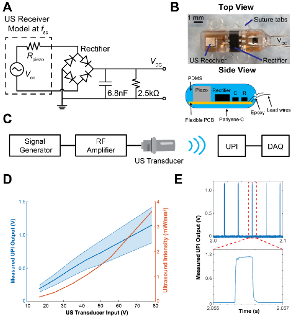
Figure 1. UPI design and in vitro characterization. (A) The circuit schematic of the UPI device. (B) Top view of the device and side view schematic of a UPI showing internal components (Piezo: US Receiver, R: resistor, C: capacitor), suture tabs, and lead wires. (C) The wireless measurement setup diagram. DAQ: data acquisition unit. (D) Measured acoustic intensities of US transducer under different transducer input voltages (orange curve) and measured output voltages averaged across all 7 UPIs in response to different transducer input voltages (blue curve). The blue shaded area indicates the output voltage range from 7 UPIs. (E) Example measured output waveform from one UPI. Each pulse is 500 µs repeating every 20 ms.
Download figure:
Standard image High-resolution imageDevices were fabricated by placing all the components onto a flexible printed circuit board (PCB). Then the populated flexible PCBs were encapsulated with polydimethylsiloxane (PDMS, Sylgard 184, Dow Corning) using a custom mold. The encapsulation design incorporated suture tabs to improve stability upon implantation. In addition, the devices were designed to eliminate sharp edges to minimize the risk of irritation. A minute amount of medical grade epoxy (EPO-TEK-301, Epoxy Technology, USA) was applied at the wire and PDMS interface for enforcement. Finally, devices were uniformly coated with 7 µm thick layer of Parylene-C to further enhance encapsulation. Figure 1(B) shows the photo of top view as well as the side view schematic of a fully fabricated UPI with all the components. The UPI prototype excluding the suture tabs and lead wires is measured to be 8.0 × 2.5 × 2.8 mm3.
Measurement setup for wireless powering test
To deliver US power to the UPIs, a 1 MHz unfocused US transducer (A314S, Olympus) was used as the external transmitter. A custom 3D printed housing was attached to the transducer to hold an US gel pad (Aquaflex, Parker Laboratories) to extend the transmission distance during measurements. The acoustic output of the US transducer along with the gel pad in the housing was characterized in a water tank at different locations using a hydrophone (HNC-1500, ONDA), which was spatially adjusted by a three-axis linear stage. Based on the measured voltage on the hydrophone and conversion coefficient provided by the manufacturer, acoustic intensities for different input voltages across the transducer (17, 25, 35, 43, 50, 56, and 78 V peak-to-peak) at 1 MHz were determined.
To generate the desired powering waveform, a custom MATLAB script was used to trigger a signal generator every 20 ms (50 Hz). The signal generator was set to output 500 sinusoidal cycles at 1 MHz at each trigger (500 µs pulse width). Output from the waveform generator was delivered into a 55 dB RF amplifier (1040L, Electronics & Innovation) to drive the US transducer. Each UPI was subjected to one minute of US exposure at the various transducer input voltages for the wireless powering test. To record the device DC output voltage under US exposure, the lead wires from the UPI were connected to a data acquisition unit (NI-USB 6361, National Instruments). The recorded raw data was processed by applying a bandpass filter (10–200 Hz) to reduce noise. Maximum voltages of the filtered data at each trigger were then averaged and recorded. The diagram of wireless measurement setup is illustrated in figure 1(C).
In vitro device characterization
For each of the UPI devices (n = 7), pre-implant scanning electron microscopy (SEM) images were captured to assess surface integrity, and device outputs were measured in vitro to confirm functionality prior to implantation. High magnification SEM images (Jeol 6390LV) were captured under low vacuum mode with 5 kV of electron acceleration. After SEM imaging, UPIs were placed under the US transducer with a gel pad for in vitro wireless powering characterization using the measurement setup described earlier. To further ensure complete contact between the UPI and transducer, US gel (Aquasonic) was also applied between the gel pad and the devices. Figure 1(D) shows the relationship between acoustic intensities at the center of the gel pad surface and the transducer input voltages, as well as the measured UPI output voltages averaged across all implants at different transducer input voltages. The output voltage from the UPI is around 1 V when 78 V is applied at the transducer. With 2.5 kΩ resistor on the UPI, 0.4 mW usable power is obtained. For applications that need more power and energy, the UPI circuit can be modified to include a large storage capacitor for charge storage. The raw output waveform of 500 µs pulse width at 50 Hz from one of the UPIs under US exposure is shown in figure 1(E).
Surgical procedure and In vivo characterization
To record UPI output after implantation, the two lead wires attached to the UPIs were cut to 55 mm in length from the base of the UPIs and threaded through 25 mm long silicone tubing. Ends of the lead wires were soldered to the pins of a connector (PZN-06-VV, Omnetics Corporation). A custom 3D printed connector mount was designed to house the connector; the bottom part of the connector mount was made of Nylon and the top was made with bronze infused stainless-steel. These two parts were bonded with epoxy (Loctite Hysol) and a 20 × 25 mm piece of Mersilene mesh was attached to the bottom surface. The connector was then inserted into the 3D printed housing and secured using epoxy. Finally, the tissue contacting surface of the connector mount was covered with Kwik-Cast (World Precision Instruments Inc.) to minimize animal discomfort after implantation [17, 18]. Figure 2(A) shows the assembled UPI along with the connector mount. Before implantation surgeries, all UPIs were sterilized using Ethylene Oxide process.
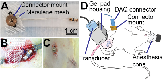
Figure 2. Surgical implantation of UPIs. (A) Photograph of a fully assembled UPI device. (B) Placement of UPI over the biceps femoris muscle. (C) Post-surgical image showing the connector mount and skin closure over the UPI on the right leg. (D) Schematic of in vivo wireless powering test setup showing placement of US transducer over the UPI implant, with US gel applied over the skin (pink). Animals were anesthetized during UPI output measurements.
Download figure:
Standard image High-resolution imageThis animal study was approved by the Institutional Animal Care and Use Committee (IACUC) at the U.S. Food and Drug Administration, White Oak campus. Experiments were performed on Female Lewis rats (n = 10), weighing between 230–280 g (5–8 months at the time of surgery), purchased from Charles River Laboratories International Inc. UPIs were implanted in n = 7 animals, while n = 3 animals were not subjected to surgical procedures and served as naïve control for histological comparison. Following standard protocol, animals were acclimated for 5 d upon receipt and housed with 12 h light and dark cycles. Before surgeries, animals were anesthetized with 4% isoflurane followed by administration of ketamine (75 mg kg−1) and dexmedetomidine (0.25 mg kg−1) cocktail intraperitoneally. Dehydration was prevented with subcutaneous administration of warm saline (3 ml), and the body temperature was maintained using heating pads. Meloxicam (2 mg kg−1, s.c.) and baytril injectable (7.5 mg kg−1, s.c.) were administered for analgesia and infection control respectively. Upon confirming the loss of toe pinch reflex, the lumbar region along with the right hind limb was shaved and disinfected with alcohol and betadine. Two ~20 mm long skin incisions were made for implantation: one over the lumbar fascia and the other over the right biceps femoris muscle (leg incision). Using blunt scissors, the skin between the two incisions was freed from connective tissue to allow for tunneling of UPIs. The device was first tunneled under the skin from the lumbar incision to the leg incision, and the connector mount was secured to the underlying lumbar fascia using 4-0 Polypropylene sutures (Oasis). The UPI along with a ~15 × 15 mm Mersilene mesh was then sutured to the underlying muscle as shown in figure 2(B). Skin around the connector mount was closed using 4-0 Polypropylene sutures and staples were applied to the skin over the implant site as shown in figure 2(C). To prevent infection, topical antibiotic ointment was applied to the incision sites. Finally, animals were administered 3 ml of warm saline subcutaneously, and the anesthesia was reversed with atipamezole (0.5 mg kg−1, i.p.). To prevent post-surgical pain and infections, meloxicam (2 mg kg−1, s.c.) was further administered for 2 d after surgery, and trimethoprim-sulfamethoxazole (48 mg kg−1, oral) was administered for 5 d in a red tinted water bottle. Remaining skin sutures and staples were removed 10 d post-surgery.
After two weeks of recovery from surgical procedures, each animal was tested three times per week for 10 weeks. During wireless powering tests, animals were anesthetized with isoflurane (4% induction, 2% maintenance) and placed on a circulating water heating pad. The measurement setup was as described in the previous section. US gel was used between the gel pad and the animals' skin to enhance coupling. Position of the transducer was manually adjusted until a maximum output voltage was obtained for the first measurement. Animals were subjected to one minute of US (500 cycles at 1 MHz at 50 Hz) at each voltage step (17, 25, 35, 43, 50, 56, and 78 V) with a 30 s pause period between each voltage step. The in vivo wireless powering measurement setup is shown in figure 2(D). To maintain consistency for histological analysis, this testing protocol was applied to the animal even when output voltages from the UPIs could not be recorded. Additionally, the rats' contralateral legs were also exposed to the same US levels to study the effects of long-term sonication on muscle and skin in the absence of a UPI.
Terminal device characterization
After 12 weeks of implantation, animals were euthanized with sodium pentobarbital (200 mg kg−1, i.p.) followed by device extraction. Immediately following extraction, lead wires were trimmed from the connector mount and in vitro wireless powering test was conducted again on each of the seven UPIs to check for functionality. After the measurements, devices were submerged in a solution containing 1% Tergazyme (Alconox) in deionized water for 48 h on a laboratory shaker for cleaning biological debris. Devices were then removed from the shaker, rinsed in water, and air dried for SEM characterization to assess the post-explant surface integrity.
Histological assessment
Qualitative histology using Hematoxylin and Eosin (H&E) staining was performed to assess the effects of implants and US exposure on surrounding skin and muscle. Skin and muscle around the UPI on the right leg, along with the contralateral (left leg) tissues were harvested and immersion fixed overnight in 4% paraformaldehyde solution at 4 °C. Control skin and muscle tissues from naïve animals (n = 6 samples, right and left hind limb) were obtained for comparison. After fixation, samples were rinsed in phosphate-buffered-saline and embedded in paraffin (ASP300S, Leica Biosystems). Skin samples were oriented to obtain cross-sections, while muscle samples were oriented for longitudinal sections. Approximately 10 µm thick sections were cut, deparaffinized, and stained with H&E using a Leica ST5020 Multistainer. Bright-field images were acquired at 20 × using a Zeiss fluorescent microscope for analysis.
Results
Implant design
In this study, we focused on assessing the long-term in vivo performance of UPI using a rodent model. The device was encapsulated with PDMS and then coated with an additional thin layer of Parylene-C. The device fabrication, especially for encapsulating the internal components was repeatable using a molding method. The UPI did not have any sharp edges, which was a critical design requirement to avoid animal discomfort upon implantation (figure 4(E)). The lead length of 55 mm was selected for the fully assembled devices based on prior experiments to accommodate for increase in animal size with age. The in vitro wireless testing of UPI confirmed device functionality before implantation with measured output ranging between 0.4 V to 0.7 V across all devices for an acoustic intensity of 1 mW mm−2 (figure 1(D)). The shape of the output waveform was consistent with circuit simulation (figure 1(E)).
In vivo device performance
During the entire study, there were no UPI related adverse events. As shown in figure 4, skin over the UPI implant healed completely without any signs of infections. The region around the connector mount healed well without signs of infection, which is critical for interfacing with the UPI implant over long periods of time. More importantly, the connector mount provided a seamless access point to interface with the implanted UPI throughout the experimental period. We also did not observe macroscopic damage to the skin on the contralateral side, which was exposed to US.
The in vivo measurements from implanted UPI during wireless powering experiments are shown in figure 3. The violin plot illustrates the distribution of measured voltage outputs from all functional UPIs. The white dot in the box plot inside the violin plot represents median and the gray bar inside the violin plot represents interquartile range. The measured output voltages varied over testing period, mainly due to misalignment between the transducer and the UPIs, as the transducer had to be repositioned for each test for all seven animals. The orientation of the implanted UPIs might also change slightly due to animal movement. Nonetheless, the measured output waveform shape was maintained throughout the implantation period, indicating that the encapsulation used in the UPIs was able to reliably protect the US receiver and the internal circuitry in an in vivo environment. The in vivo measured output voltages were less than the measured values from in vitro testing in figure 1(D) because the transmission distance and the attenuation were larger due to animal tissue in the powering path.

Figure 3. In vivo UPI output measurement. Violin plot with box plot inside showing measured device output in response to various transducer input voltages over 12 weeks from all functional UPIs. The white dot in the box plot represents median and the thick gray bar in the center represents interquartile range. Subplot shows the number of UPIs with measurable device output over time.
Download figure:
Standard image High-resolution imageThe subplot in figure 3 shows the number of UPIs with measurable device output over time. Three implants consistently generated outputs under US exposure for the whole implantation period, demonstrating UPIs were able to receive US power and function long-term in the animals. Outputs from four devices could not be recorded starting at different time points (Device 1: day 51, Device 2: day 42, Device 4: day 51, Device 5: day 35). Since the event happened abruptly; we initially suspected the issue lay in the interfaces close to device or the connector, perhaps due to shorting or mechanical failure on the connector instead of the devices themselves. This was later confirmed by the in vitro wireless powering test after explanting UPIs. An improved strategy should be used in the future for connector assembly to strengthen the interface between the connector and the lead wires to sustain long-term implantation.
Device assessment after explant
Devices were covered in a fibrotic capsule at the time of harvest as seen in figure 4(B). The incorporation of suture tabs prevented dislodging of the UPIs after implantation. An important aspect for UPIs to be safe and implantable was preventing skin erosion and irritation; the use of Mersilene mesh and rounded shape of the implant encapsulation both helped in this regard. The skin and muscle tissue surrounding the device also showed no signs of macroscopic damage as seen in figures 4(B) and (C). The explanted devices were further characterized for functionality and surface damage with in vitro wireless test and SEM imaging.
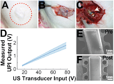
Figure 4. Terminal procedures. (A) Healed skin over UPI after 12-week implantation period. Red circle is drawn around the region of implantation. (B) Harvest image showing tissue ingrowth and encapsulation of the implanted Mersilene mesh, which is placed over the UPI implant. (C) Exposed UPI device after 12 weeks of implantation. (D) Measured average in vitro output voltages across all 7 UPIs after harvest to test device functionality. (E) SEM image of a UPI prior to implantation. (F) SEM image of a UPI after explantation and cleaning.
Download figure:
Standard image High-resolution imageFor post-explant in vitro wireless powering tests, all 7 UPIs were separated from the connector mount assembly before testing. All UPIs were able to generate outputs under US exposure, confirming that the failure in the in vivo stage was due to lead wire related issues at the connector mount interface. Figure 4(D) shows the average and the range of output voltages across all UPI devices under different input voltages across the US transducer. The average output levels measured post-explant increased compared to the ones measured before implantation (figure 1(D)), which could be attributed to the potential difference in transducer placement over the device. Pre- and post-implantation SEM images of the devices are shown in figures 4(E) and (F). It can be observed that the UPI stayed intact, and the materials used did not undergo observable structural changes during the long-term implantation period. Nonetheless, the suture tabs of one device displayed small signs of wear; this deformation is likely due to application of suture at the time of implantation
Histological assessment
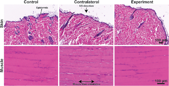
Muscle and skin surrounding the UPIs were assessed using H&E staining and compared to contralateral (exposed to US) and control (naïve) muscle and skin as shown in figure 5. The epidermal and dermal layer of the skin were visible without signs of excessive fibrosis or formation of necrotic tissues. Similarly, the biceps femoris muscle around the UPI implant did not exhibit characteristics of macroscopic injury when observed at the time of harvest, and the H&E images did not indicate damage across all devices. Both skin and muscle between the three groups were comparable, indicating that the UPI and US exposure did not induce tissue injury. While we did not observe tissue injury in this study, further studies must be conducted to specifically assess tissue injury and establish implant safety.
Figure 5. Histological assessment: histology results from three different groups, control (no implant, no US), contralateral (no implant, but with US), and experiment (with implant and US). Skin samples were oriented for cross-sections and muscles samples were oriented for longitudinal sections. Arrow pointing to the direction of US exposure at the surface of the skin. The US direction is aligned perpendicular to the muscle fiber orientation.
Download figure:
Standard image High-resolution image
Discussion
Active medical implants have been used for the treatment of various diseases and conditions, with numerous applications currently under investigation [19, 20]. These active devices are typically powered by batteries [21, 22], which increases the overall volume of the device. The large form-factor of the device may be limiting in applications where devices are placed close to critical organs, such as visceral nerves that are deep within the body [23]. In such cases, miniaturized wireless implants, such as the prototype devices used in this study may prove to be beneficial. Previously, miniaturized US powered implants have been demonstrated for recording electromyography and electroneurography signals in rodents in vivo [15]. Similarly, the UPI architecture can potentially be tailored for different medical applications, for example, neural stimulation and recording capabilities can be included into the system design in the future [13]. The device size can also be further reduced by integrating the resistor and capacitor into the chip. However, to isolate failure modes associated with UPI devices, the prototype UPI was designed to only generate DC voltage output when receiving US energy. This simple design was used to avoid confounding factors that could result from addition of functions such as neural stimulation or recording.
As the device is powered by US, materials used for encapsulating the piezoelectric receiver in the UPI must be selected such that it allows acoustic energy to pass through for the device to function as desired. In this study, we used PDMS and Parylene-C for their acoustic properties and favorable acoustic power transfer [24], to maintain high-link power transfer efficiency. This combination of materials used for encapsulating the prototype UPI has not been assessed for long-term functionality of similar devices, and hence provides significant information for future device development. Other common compatible materials such as Titanium and ceramics can potentially be used if they are thin enough to allow acoustic energy to pass-through [25]. While we did not observe UPI failure resulting from implantation during the entire course of the study, we encountered issues at the connector mount interface. This could potentially be mitigated by protecting and strengthening the interface with PDMS and Parylene-C as with the device body.
Assessment of the UPI with in vitro testing was used to confirm device functionality and reprodu-cibility of output voltage under US exposure. This was a critical step to assess the overall device fabrication process. While in vitro testing did not pose challenges for aligning the external transducer with the UPI, one of the difficulties during the in vivo testing was achieving and maintaining optimal alignment between the US transducer and the UPIs, especially since the internal components were not visible. Although the UPIs were able to generate voltage outputs in the animal under ultrasound as shown in figure 3, the variance of measured outputs across different days was observed. This is because the received power by the UPIs is not always constant due to placement of the transmitter, coupling to the tissue, or orientation of the UPIs after implantation inside the animal. There could be multiple potential solutions to mitigate this issue, such as (1) using a more omnidirectional US receiver in the UPI with the cost of power transfer efficiency, (2) integrating imaging or localization capabilities on the external US transmitter, such that device can be visualized prior to wireless power delivery, or even concurrently [25], and (3) incorporating functionality to report the received power level at the implant wirelessly; for example, this wireless communication can be done through RF [13].
Skin erosion has been observed with subcutaneous implants resulting from increased pressure on the skin [26, 27]. During the long-term implantation, we did not observe skin erosion or other adverse events as shown in figure 4(A). Utmost care was taken during both device design and at the time of surgery to avoid adverse effects of UPI implantation. For example, incorporating round edges and creating a flat bottom to anchor the UPI in place, and the use of Mersilene mesh over the device resulted in tissue ingrowth as shown in figure 4(B), which provided additional layer of protection against skin erosion. It is also important to note that the devices were intact at the time of harvest as shown in figures 4(C) and (F) and continued to function during the post-explant testing as shown in figure 4(D). Taken together, we found that the combination of device design and optimum surgical techniques resulted in long-term device functionality in vivo. However, we found a difference in in vitro UPI output between pre-implantation and post-explantation testing. This difference could be attributed to the lack of connector during post-explantation testing, in addition to the variation in US transmitter coupling and orientation. To improve consistency of in vitro device output measurements between pre-implantation and post-explantation testing, a connector interface could be re-attached to the lead wires in addition to closely replicating the placement of US transmitter over the UPI.
Histological assessment of the skin and muscle was conducted around the UPI, on the US exposed contralateral side, and on naïve control tissue (figure 5). The objective for using qualitative histology was to study observable differences in the skin and muscle around the UPI that could have resulted from device components and device function. With qualitative histological assessment, we did not observe injuries that resulted from either device function or its components as shown in figure 5. It is also important to note that long-term exposure to US on the contralateral tissue did not indicate injury. Overall, the three groups were comparable as observed in this study. A more extensive quantitative histological analysis and further investigation on device performance can be conducted in the future to establish device safety and efficacy for current and future applications.
Conclusion
We developed a set of tests and applied it to assess the long-term performance of UPI. We recorded US powered electrical output in vivo and identified a failure mode that impacted some of the devices. The device encapsulation strategy was robust for long-term applications. Both the presence of UPI and application of US over the long experimental period did not induce injury to surrounding skin and muscle tissues. This testing protocol could be extended and applied to a wide variety of US-powered devices. The parameters may be adjusted based on the applications; for example, the implantation period can be prolonged and different frequencies of wireless powering can be used. Potential improvements aside, the evaluation platform designed and reported here can be a functional foundation for future assessment of implantable devices of similar nature.
Acknowledgments
Financial support for this research was provided by the Division of Biomedical Physics, Office of Science and Engineering Laboratories, Center for Devices and Radiological Health, U.S. Food and Drug Administration, Silver Spring, MD; Defense Advanced Research Projects Agency, Biological Technologies Office, Electrical Prescriptions (ElectRx) Program and National Science Foundation (NSF) CAREER Award under Grant ECCS-1454107.
Disclaimer
The mention of commercial products, their sources, or their use in connection with material reported herein is not to be construed as either an actual or implied endorsement of such products by the Department of Health and Human Services.