
Abstract
Dye-sensitized solar cells (DSCs) have attracted a great deal of attention due to their low-cost and high power conversion efficiencies. They usually utilize an interconnected nanoparticle layer of TiO2 as the electron transport medium. From the fundamental point of view, faster mobility of electrons in ZnO is expected to contribute to better performance in DSCs than TiO2, though the actual practical situation is quite the opposite. In this research, we addressed this problem by first applying a dense layer of ZnO on FTO followed by a mesoporous layer of interconnected ZnO nanoparticle layer, both were prepared by spray pyrolysis technique. The best cell shows a power conversion efficiency of 5.2% when the mesoporous layer thickness is 14 μm and the concentration of the N719 dye in dye coating solution is 0.3 mM, while a cell without a dense layer shows 4.2% under identical conditions. The surface concentration of dye adsorbed in the cell with a dense layer and that without a dense layer are 5.00 × 10⁻⁷ and 3.34 × 10⁻⁷ mol/cm2, respectively. The cell with the dense layer has an electron lifetime of 54.81 ms whereas that without the dense layer is 11.08 ms. As such, the presence of the dense layer improves DSC characteristics of ZnO-based DSCs.
Export citation and abstract BibTeX RIS
1. Introduction
Recent research activities in the field of dye-sensitized solar cells (DSCs) have drawn a great deal of attention towards improving their performances. Since the first report of the highly efficient, TiO2 mesoporous structure-based DSC, by O'Regan and Grátzel in 1991[1], many alternative semiconductors such as ZnO[2] and SnO2[3–5] have been investigated to replace TiO2 in DSCs. However, TiO2 still holds the record for the best power conversion efficiency, which has now risen to the 15.4% bench mark[6]. Both ZnO and TiO2 have a similar band gap of ~3.2 eV and also comparable band positions[7]. Furthermore, ZnO has much lower effective electron mass (meff ~0.26) compared to that of TiO2 (meff ~ 9)[7, 8], which results in a much higher electron mobility in ZnO (205–300 cm2 V−1 s−1) compared to that in TiO2 (0.1 cm2 V−1 s−1)[2, 7]. As such, based on theoretical arguments, ZnO should behave in a superior way to TiO2 in DSC applications, although the practical situation is completely the opposite. It is now known that the higher electron mobility of ZnO results in higher internal recombinations of photogenerated electrons, which in turn results in lower power conversion efficiencies[9]. Also, the amphoteric property of the ZnO limits its applications in DSCs. Since ZnO may dissolve in carboxylic acid groups present in dyes and in the basic environment provided by carboxylate groups and hence structural deformations in the ZnO nanoparticulate layer would take place due to acid/base etching. To circumvent this problem, to some extent, organic indoline-based dyes have been developed[9, 10]. Use of ZnO in DSCs has its own advantages since various forms of nanostructures of ZnO such as nanospheres, nanowires, nanotubes, nanorods, nanorings, nanobelts, nanosheets, and tetrapods of ZnO could be easily prepared[11–19]. Such a wealth of diverse structures of ZnO naturally invite researchers to investigate further into ZnO-based DSCs. Although ZnO-based DSCs show inferior performances when compared to those of TiO2-based counterparts, many researchers have already studied DSCs based on ZnO nanostructures with the aims of understanding fundamental science and improving efficiencies. As such, Keis et al. reported a 5.0% conversion efficiency for such ZnO nanoparticle-based DSC using N719 as the sensitizer. In 2008[20], Zhang et al. reported ZnO submicron sized aggregates as efficient light scattering centres in the size range of 100–500 nm and the DSC that has incorporated these large particles in the mesoporous layer gave 5.4% efficiency when N3 sensitizer was used[21]. Saito et al. reported the preparation of ZnO electrode by Squeegee method, which when used in DSC together with N719 sensitizer gave 5.2% conversion efficiency[22]. In 2010, there were two important reports for ZnO-based DSCs where, first, Chang et al. reported 5.3% power conversion efficiency with D205 metal-free indoline sensitizer[9]. This cell has utilized ZnO nanoparticulate thin film with ZnO-based light scattering centres which have been fabricated using screen-printing technology. Secondly, Rani et al. reported a ZnO electrode sensitized with a blend of five metal free dyes with a polymeric gel-based electrolyte, which gave a power conversion efficiency of 7.9%[23]. This work has clearly shown the possibility for fabricating highly efficient DSCs based on ZnO, with an unprecedented current density of 27.89 mA/cm2, at AM 1.5 illumination, which can be considered as the highest reported current density in any DSC. In 2011, Memarian et al. reported a ZnO-nanoparticulate DSC with ZnO light scattering centres comprising of large ZnO particles, and also a blocking layer of ZnO deposited between the FTO surface and the interconnected, nanoparticulate matrix[24]. Here, light scattering by submicron-sized ZnO particles has enhanced the light absorption by the dye molecules while the blocking layer has prevented the contact of the electrolyte with the FTO layer thus preventing recombination at the FTO/ZnO nanoparticulate layer/electrolyte junction. This cell has shown 7.50% conversion efficiency with the N719 sensitizer. In 2012, Premaratne et al. have reported 5.9% conversion efficiency for optically semi-transparent ZnO-based DSC using D358 as the sensitizer[10]. In 2013, Shi et al. revealed the utilization of ZnO nanoplate-like structures and the use of polymer gel electrolyte in the DSC to result in 6.46% conversion efficiency with N719 as the sensitizer[25]. In the present work, we describe the fabrication of both highly-compact dense (blocking) layer and the mesoporous nanoparticulate layer of ZnO using a simple spray pyrolysis technique and the performance of the DSCs based on such hierarchical ZnO layers in combination with N719 dye and the usual I–/I3– redox couple. Although the dense layers have been incorporated in DSCs to reduce recombination, this is the first study that utilized spray pyrolysis technology to form both dense and mesoporous layers of ZnO for their utilization in DSCs. The performances of DSCs with and without the dense layer were studied and the results obtained were verified using AC Impedance and dye-desorption studies. The effect of the mesoporous layer thickness and the concentration of N719 dye in the dye-coating solution on the performance of DSCs was also investigated.
2. Experimental
2.1. Deposition ZnO dense layer on FTO glass substrates
To prepare the precursor solution for the ZnO dense layer, ZnO (1.7 g) (Wako chemicals, Japan) was dispersed in 100 mL of a solution containing 1 : 1 v/v of ethanol (99%, Sigma Aldrich, USA) : deionized water. Acetic acid (99%, Sigma Aldrich, USA) (~10 mL) was added drop-wise with vigorous stirring until a clear transparent solution was obtained. This precursor solution was sprayed on to FTO glass substrate at 300 °C to obtain a transparent dense layer with a sheet resistance of 250–300 Ω/□.
2.2. Preparation of ZnO mesoporous layer
Commercial ZnO nanoparticles (20 nm diameter, 0.3 g) (Wako chemicals, Japan), acetic acid (3 drops) and Triton X-100 (3 drops) (99%, Sigma Aldrich, USA) were well ground using a mortar and pestle. The ground powder was transferred to a beaker and ethanol (30 mL) added and the dispersion was ultra-sonicated for 15 min. The resulted dispersion was sprayed on to FTO glass substrates, with and without dense layers, which were placed on a hot plate at 150 °C until the desired thicknesses were achieved. Then, the electrodes were subsequently sintered at 350 °C for 30 min.
2.3. Characterization of ZnO layers
Both dense and mesoporous ZnO layers were characterized using SEM (Hitachi 8030) images for their morphology and for the determination of particle size distribution. XRD (Siemens D5000, Cu Kα1, λ = 1.54056 Å) analyses were done to identify their crystal structures. Dye desorption studies were carried out using the standard method based on 0.1 M NaOH (aq) (97% VWR England) solution and the estimation of the amount of dye absorbed was done with the aid of UV–visible Spectroscopy (Shimadzu UV1800).
2.4. Dye coating
The annealed samples were allowed to cool down to 80 °C and then they were immersed, for 10 h, in N719 dye solution prepared by dissolving in 1 : 1 v/v solution of acetronitrile and tertarybutyl alcohol. In order to investigate the effect of concentration of dye, the dye solutions with concentrations of 0.1, 0.2, 0.3, 0.4, and 0.500 mol/dm3 were prepared and fresh samples were used simultaneously for the optimization.
2.5. Fabrication of DSCs
DSCs were fabricated by placing a lightly-platinized Cr- mirror type counter electrode on each of the dye-coated ZnO working electrodes, both with and without dense layers, and injecting I3–/I– based liquid electrolyte (0.1 M LiI, 0.05 M I2, 0.6 M dimethylpropylimidazolium iodide and 4-tert-butylpyridine in acetonitrile) into the space between the two electrodes. The configuration of the cells with the dense layer is FTO/ ZnO dense layer/ZnO mesoporous layer/N719 dye/I3–/I– based electrolyte/lightly-platinized, Cr-coated mirror type glass counter electrode and that without dense layer is FTO/ZnO mesoporous layer/N719 dye/I3–/I– based electrolyte/lightly-platinized Cr-coated mirror type glass counter electrode.
2.6. Evaluation of DSC performances
The cells were characterized by J–V measurements at AM1.5 simulated sunlight (Peccell L01) for 0.25 cm2 cells and their performance as functions of the thicknesses of the mesoporous layer and the concentration of the N719 dye used in the dye-coating solution were studied. In order to study the effect of the thickness of the mesoporous layer, all other parameters were kept constant, particularly the initial concentration of the dye in the dye coating solution was kept at 0.30 mmol/dm3. Then the ZnO-based working electrodes were prepared by soaking them in dye solutions with different concentrations of the dye and the thickness of the mesoporous layer was kept at 14 μm. The charge transport characteristics of the DSCs were analyzed using AC impedance analysis at −0.60 V bias under dark conditions in the frequency range of 1 MHz–1 mHz (Autolab PGSTAT 12).
3. Results and discussion
3.1. Characterization of dense and mesoporous ZnO layers
The XRD patterns of both the dense and porous ZnO layers are shown in Fig. 1. The peaks at 2θ values of, 31.65° (100), 34.65° (002), 37.18° (101), 47.25° (102), 56.45° (110), 63.75° (103), 68.43° (112), and 69.68° (201) of the mesoporous layer shown in Fig. 1(a) which are characteristic of the hexagonal Wurtzite structure of ZnO (JCPDS card No. 05-0664). Since this layer is sufficiently thick and is grown on a very thin dense ZnO layer, the basement FTO layer is not exposed for X-rays and as such diffraction peaks corresponding to FTO are absent here. Since all the peaks can be assigned to ZnO alone, it can be confirmed that there are no crystalline impurities present in this sample. The 0-D particulate nature is clearly visible since diffractions from several planes are present but most of the particles have (100) and (110) as preferred planes since the intensities of peaks corresponding to these planes are prominent in the diffractogramme. Fig. 1(b) shows the X-ray diffractogramme of the dense ZnO layer. All the diffractions given above can be located here also but with very low intensities. Besides, peaks due to FTO [26.60° (110), 33.88° (101), 37.88° (200), 51.58° (211), 54.62° (220), 61.919° (310), and 65.78 °(301), JCPDS card no. 01-0625] are also clearly visible with intensities much higher than those of ZnO, indicating the possibility for the penetration of X-rays onto the FTO surface owing to the fact that the thickness of the dense layer is very low in a few nanometers. The fact that since all the peaks can be assigned to be to ZnO and FTO, it can be confirmed that there are no crystalline impurities present in this sample also. The top view of the SEM image of the compact layer, shown in Fig. 2(a), clearly shows the presence of a very closely packed layer of ZnO in the dense layer. As shown in Fig. 2(b) the porous layer is composed of interconnected nanoparticles with an average diameter of 20 nm.

Fig. 1 (Color online) XRD pattern of, ZnO porous layer present on the dense layer deposited on FTO surface and dense layer on FTO surface.
Download figure:
Standard image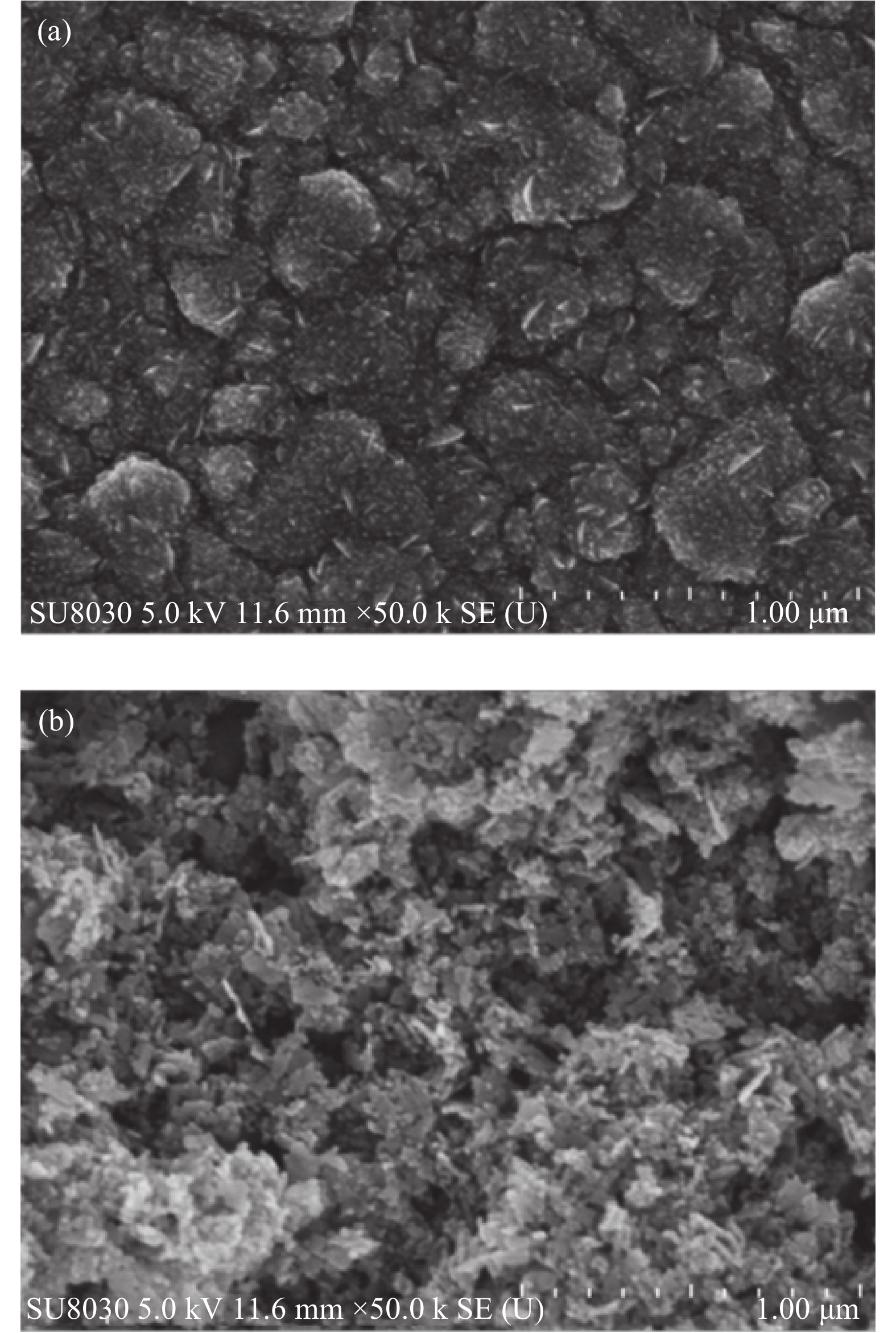
Fig. 2 Scanning electron micrographs of ZnO (a) dense layer and (b) porous layer.
Download figure:
Standard image3.2. Dye-sensitized solar cell studies
3.2.1. Effect of dense layer on DSC performance
Fig. 3 shows representative (current density–voltage)J–V curves for the DSCs fabricated with and without ZnO dense layers under identical conditions. Measured Jsc, Voc, FF and η of the DSC with the dense layer are 13.68 mA/cm2, 0.573 V, 0.663 and 5.02%, respectively, while those without ZnO dense layers are 12.06 mA/cm2, 0.565 V, 0.624 and 4.20%, respectively. As clearly evident from these data, the increase in Jsc in the presence of the dense layer can be attributed to the suppression of recombination at the FTO/ZnO/Electrolyte junction. When this recombination is suppressed by blocking the FTO surface, by introducing a very thin dense ZnO layer, more electrons will reside on the FTO for them to be transported along the external circuit when the cell is short-circuited, as measured by 13.4% enhancement of the Jsc in the DSC containing the dense layer. The change in Voc is negligible and in this case it is only a 1.4%. This is due to the fact that the blocking layer neither alters the electronic structure of the conduction band of ZnO nanoparticles nor does it affect the redox potential of the electrolyte. There is an increase of FF by 6.25% indicating that better binding of the dense layer to the FTO and the mesoporous layer to the dense layer thus facilitating for better electron transport.

Fig. 3 (Color online) J–V curves for DSCs prepared and measured under identical conditions except in the presence of the ZnO dense layer (Orange) and in the absence of ZnO dense layer (Blue).
Download figure:
Standard imageThe superiority of the cell with dense layer has been further confirmed by the AC impedance spectroscopic (AC-IS) studies of the two cells where the corresponding spectra are shown in Fig. 4.
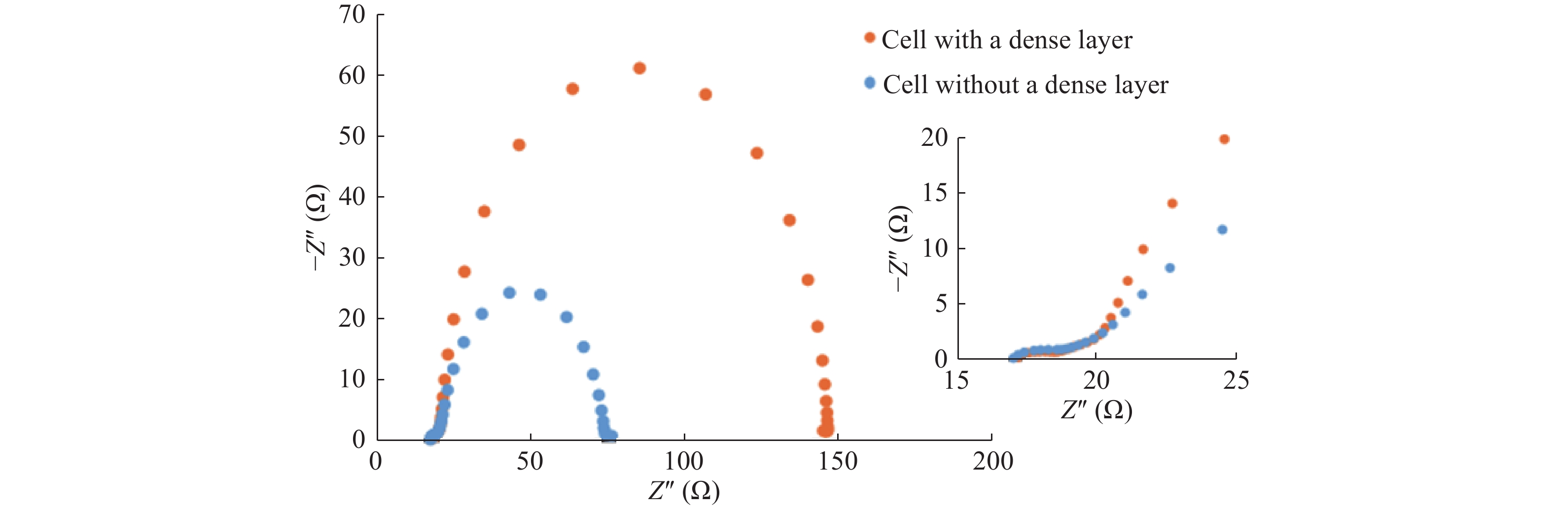
Fig. 4 (Color online) AC Impedance spectra of the DSC with a dense layer (orange) and without a dense layer (blue). (Concentration of the N719 dye in the coating solution is 0.3 mM and the thickness of the mesoporous layer is 14 μm, operating conditions are as given in the experimental section).
Download figure:
Standard imageAC-IS data of the DSCs were analyzed using the standard method put forward by several researchers[26, 27]. The cell with dense layer has shown an electron lifetime (τ) of 54.81 ms whereas the cell without dense layer has shown 11.08 ms under identical conditions. Also, the two cells have shown recombination resistance (Rre) of 126 and 53.8 Ω, respectively. The relationship of chemical capacitance (Cμ) and the recombination resistance is given by the τ = CμRre[26, 27]. Here, it is clear that the better attached ZnO structures have provided more favourable conditions for electron transport than those without dense layers. The dense layer in the cell has suppressed the recombination of the cell and thereby increased the lifetime of the photogenerated electrons by almost fivefold. In practice, the dense layers prepared at high temperatures have high adhesion properties on to FTO than those of porous layers which are fabricated at lower temperatures. In the same analogy, the ZnO porous layer which was fabricated on the ZnO dense layer has produced a perfect mesoporous structure to result in higher resistance for recombination. The increase in the fill factor of the cell with the dense layer clearly indicates the good contact of ZnO layers with the FTO layer when the dense layer is present than when it is absent. This is further supported by the increase in the short circuit current density which we discussed earlier.
It is interesting that the dye desorption measurements carried out using these two types of optimized working electrodes have also shown an increment in dye loading in the presence of the dense layer. The absorption spectra of the dye desorbed using 0.10 M NaOH solution from the two cells, separately, are shown in Fig. 5. The calculated dye amounts adsorbed in the working electrodes of the two cells, with active area of 0.25 cm2 and mesoporous layer thickness of 14 μm, with the dense layer and without dense layer are 5 × 10⁻⁷ and 3.34 × 10⁻⁷ mol/cm2, respectively. The dye adsorption is nearly 1.5 times higher when the dense layer is present. As the thickness of the porous layer is the same in the two cells, the increased dye loading is probably due to more favourable arrangement of the porous ZnO layer on top of the ZnO dense layer rather than assembling the ZnO porous layer on FTO. The high dye coverage in the system could easily improve the current generation in the cell giving a higher short-circuit current in the presence of the dense layer.

Fig. 5 (Color online) UV–visible absorption spectra of the dye desorbed from 0.25 cm2 and mesoporous thickness of 14 μm electrodes, with the dense layer (Orange) and without dense layer (Blue). [In both cases, concentration of N719 dye used in the dye solution is 0.3 mM and the thickness of the mesoporous layer is 14 μm].
Download figure:
Standard image3.2.2. Effect of mesoporous layer thickness on DSC performance
J–V characteristics of DSCs employing ZnO working electrodes with identical dense layers but different mesoporous layer thickness are depicted in Table 1. The highest power conversion efficiency is observed for the DSC with the mesoporous layer thickness of 14 μm. This DSC shows an impressive short circuit current density (Jsc) of 13.68 mA/cm2, open circuit voltage (Voc) of 0.573 V, fill factor of 0.663 and consequent power conversion efficiency of 5.20%. The efficiency of DSCs increases as the thickness of the mesoporous layer increases up to 14 μm due to increased dye adsorption and consequent increased electron injection. The decrease of performance at higher mesoporous layer thickness is due to increased electron transport length resulting in increased recombination of electrons harvested from dye molecules residing at the far end of the nanoparticles before reaching the FTO surface, as demonstrated very clearly for TiO2-based DSCs[26, 27].
Table 1. J–V characteristics of the DSCs employing working electrodes with a dense ZnO layer and different thicknesses of the ZnO porous layer (N719 concentration of the dye-coating solution is 0.3 mM, under simulated sun light of AM 1.5 illumination and active area of 0.25 cm2) comparison with other published PGA.
| Thickness of mesoporous layer (μm) | Jsc (mA/cm2) | Voc (V) | Fill factor | Efficiency (%) | ||
|---|---|---|---|---|---|---|
| 3 | 8.29 | 0.593 | 0.673 | 3.3 | ||
| 6 | 10.42 | 0.549 | 0.627 | 3.6 | ||
| 8 | 10.47 | 0.554 | 0.640 | 3.7 | ||
| 11 | 10.69 | 0.584 | 0.613 | 3.8 | ||
| 14 | 13.68 | 0.573 | 0.663 | 5.2 | ||
| 18 | 10.05 | 0.561 | 0.663 | 3.7 | ||
| 21 | 8.52 | 0.603 | 0.679 | 3.5 |
3.2.3. Effect on DSC performance by the initial concentration of dye in the solution used for dye absorption
Collected in Table 2 are the J–V characteristics of the cells with respect to the concentration of N719 dye used in the dye adsorption solution by keeping the porous layer thickness constant at 14 μm. The DSC shows the highest power conversion efficiency when 0.30 mM/dm3 of N719 is used. At higher concentrations of the N719, I is possible for multilayer dye coverage which would hamper light absorption and hence lower the power conversion efficiency. Also lower concentrations than 0.03 mM/dm3, the dye concentration may be insufficient for full surface coverage and this may reduce the electron injection and increase the recombination of injected electrons with I3– ions. This may explain the progressively increased performance up to the complete surface coverage that can be achieved from 0.30 mM dye solution.
Table 2. J–V characteristics of the cells (0.25 cm2 active area) containing ZnO dense layer when the initial concentration of N719 dye in the dye-adsorption solution is varied at constant ZnO porous layer thickness of 14 μm.
| Concentration of N719 dye (mM) | Jsc (mA/cm2) | Voc (V) | Fill factor | Efficiency (%) | ||
|---|---|---|---|---|---|---|
| 0.10 | 7.70 | 0.558 | 0.670 | 2.9 | ||
| 0.20 | 10.10 | 0.558 | 0.650 | 3.7 | ||
| 0.30 | 13.68 | 0.573 | 0.663 | 5.2 | ||
| 0.40 | 12.36 | 0.572 | 0.660 | 4.7 | ||
| 0.50 | 10.05 | 0.561 | 0.663 | 3.7 |
4. Conclusion
The preparation and characterization of a mesoporous ZnO structure on a ZnO dense layer for applications in DSCs were revealed. The ZnO mesoporous layer has been fabricated on the ZnO dense layer and N719 dye was used as the sensitizer for the working electrode. The cells with an active area of 0.25 cm2 were assembled with the configurations of FTO/ZnO dense layer/ZnO mesoporous layer/N719 dye/(I3–/I–) based electrolyte/lightly-platinized Cr-coated mirror type counter electrode (cells with the dense ZnO layer) and FTO/ ZnO mesoporous layer/N719 dye/(I3–/I–) based electrolyte/lightly platinized Cr-coated mirror type counter electrode (cells without dense layer), respectively. The cells with and without dense layer have shown power conversion efficiencies of 5.2% and 4.2%, respectively, under AM 1.5 illumination. The impedance analysis has shown that electron lifetimes in the working electrodes of the cell with the dense layer and that without the dense layer are 54.81 and 11.08 ms, respectively. The higher performance of the cell with the dense layer has been further confirmed by the dye desorption measurements where the amounts of dye absorbed in cells with and without dense layers are 5 × 10⁻⁷ mol and 3.34 × 10⁻⁷ mol, respectively. The effects of mesoporous layer thickness and the concentration of N719 dye in the dye-coating solution on the performances of the DSCs with the dense layer were studied. The optimum ZnO mesoporous layer thickness and the N719 dye concentration were found to be 14 μm and 0.3 mM, respectively. Linearity and resolution of the delay line have a large effect on the transmitter performance. In order to overcome the bottleneck of low linearity and low resolution, an improved delay line structure is proposed with a calibration algorithm to conquer PVT variations for this all-digital design. Measurement results show that the proposed structure with the calibration algorithm can evidently improve the linearity and resolution of the delay line.