Abstract
Radio frequency signal compatibility is the basis of interoperability of the Satellite e-Based Augmentation System (SBAS). SBAS should abide by relative international radio regulations of International Telecommunication Union (ITU) and meet the compatibility requirements of radio frequency signal between the Global Navigation Satellite System (GNSS)/SBAS, in order to avoid negative mutual interference. According to ITU Proposal and related reference and assumptions, the paper made simulation of signal receiving maximum power in the BeiDou Satellite-Based Augmentation System (BDSBAS) global signal coverage. And then, interference of BDSBAS to Global Positioning System (GPS)/WAAS (Wide Area Augmentation System) on L1/L5 bands were calculated and analyzed, with equivalent carrier-to-noise ratio as the evaluation parameter. The result shows that the carrier-to-noise ratio decrease of GPS/WAAS caused by BDSBAS B1C and B2a signals are extremely lower than inter-system interference of GPS/WAAS, and thus can be ignored in practical applications. Therefore, BDSBAS will not cause the service performance degradation of GPS and WAAS.
Export citation and abstract BibTeX RIS
1. Introduction
The Satellite e-Based Augmentation System (SBAS) is a wide-area differential system that provides augmentation information (integrity and orbit/clock/ionospheric delay corrections) for one or more core Global Navigation Satellite System (GNSS) constellations. The non-airborne element uses a network of ground-based reference receivers to monitor GNSS ranging signals, calculates differential corrections at a central computing facility, and broadcasts the corrections in a standard message format to the airborne user through the satellite link. The airborne element receives GNSS ranging signals and the corrections information, and then applies the corrections in the process of calculating a navigation solution. Integration of the airborne element into an airframe permits use of the navigation solution (position and protection level) for navigation, guidance, and surveillance information, enabling en-route through precision approach operations while supporting surveillance applications such as ADS-B (Automatic Dependent Surveillance-Broadcast).
At present, the world SBAS includes WAAS (Wide Area Augmentation System) of American, EGNOS (European Geostationary Navigation Overlay Service) of Europe, SDCM (System for Differential Corrections and Monitoring) of Russia, MSAS (MTSAT Satellite-based Augmentation System) of Japan, GAGAN (GPS Aided GEO Augmentation Navigation) of India, KASS (Korea Augmentation Satellite System) of Korea, and BDSBAS (BeiDou Satellite Based Augmentation System) of China, etc. SBAS carries out system construction and service in accordance with ICAO (International Civil Aviation Organization) standards. In the future, SBAS will achieve global aviation integrity service through compatible interoperability and the convergence of their respective aviation service areas. In this case, radio frequency signal compatibility is the precondition of interoperability of SBAS. SBAS should abide by relative international radio regulations of ITU (International Telecommunication Union), avoid negative interference, and satisfy radio frequency signal compatibility requirements between GNSS and SBAS.
BDSBAS is an important part of BDS (BeiDou Navigation Satellite System), which is also an SBAS service provider of ICAO, will carry out the design, construction and test in accordance with the minimum ICAO SARPs (Standards and Practices) performance specifications (Development of BeiDou Navigation Satellite System 2018). In 2017, BeiDou and GPS have already completed the frequency coordination of civil RNSS (Radio Navigation Satellite System) signals. According to ITU-RM. 1831 Proposal (International Telecommunication Union 2015) and related reference and assumptions, and the overlap of BDSBSA and GPS/WAAS signals in L1/B1C and L5/B2a band, the mathematical model of spectral separation coefficient (SSC) is used to simulate the maximum power of signal reception in the global coverage area of BDSBAS single satellite and constellation in this paper. Furthermore, the aggregate gain factor of the overlapping coverage area of BDSBAS and GPS/WAAS is obtained. On the basis, considering the equivalent carrier-to-noise radio as the evaluation index of inter-system interference, the interference in GPS/WAAS L1 and L5 bands caused by BDSBAS is calculated and analyzed, and is comparing to the inter-system interference of GPS/WAAS. Relevant results show that the reduction of carrier-to-noise of GPS/WAAS L1 and L5 signals caused by BDSBAS B1C and B2a signals is extremely low, and generally far less than the reduction of carrier-to-noise radio caused by intra-system interference of GPS/WAAS. Thus, it would not cause the degradation in performance of GPS/WAAS, and can be ignored in practical applications.
2. Signals Distribution
BDSBAS is an important part of BeiDou Navigation Satellite System (BDS), includes three Geostationary Earth Orbit (GEO) satellites of BDS. In IWG 31# meeting, November 2016, the SBAS service providers jointly signed and adopted SBAS L5 DFMC Interface Control Document (v1.3) and Satellite-Based Augmentation System Dual-Frequency Multi-Constellation Definition Document (v2.0), in which BDS is selected as one of the augmentation constellations of DFMC SBAS. In October 2017, Global Positioning Systems Directorate assigned BDSBAS temporary use of PRN code sets 130, 143 and 144, and BDSBAS will make use of the PRN codes on GPS L1 C/A and L5 signals. It was also in October 2017, the ICAO NSP fourth meeting assigned BDSBAS the SBAS service provider identifier 5 and SBAS UTC (Universal Time Coordinate UTC) standard identifier 5. On 2018 November 1, the first BDSBAS GEO satellite was launched successfully, with orbit 140E and PRN 130 (Xinhua Net 2018). This satellite is also the first GEO of BDS-3.
In the future, China will carry out the design, test and construction of BDSBAS in accordance with the minimum ICAO Standards and Practices (SARPs) performance specifications (ICAO SARPs 2006; DO-229E 2016), and provide service to the civil aviation, maritime, railways and other users with high integrity requirements in China and its surrounding areas (Civil Aviation Administration of China (CAAC) 2017).
BDSBAS signals are parts of BDS signals (RNSS), which have been declared to ITU for network resources together with them. The system parameters described herein reflect the characteristics of the BDSBAS signals identified in the Chinese ITU filings listed in Table 1, which fall in the frequency bands of 1559 MHz to 1610 MHz and 1164 MHz to 1300 MHz.
Table 1. ITU Filings Applied for BDSBAS
| Network Name | Orbital Location | ITU publication reference | IFIC |
|---|---|---|---|
| COMPASS-80E | 80E | PART II-S | 2658 |
| COMPASS -110.5E | 110.5E | PART II-S | 2658 |
| COMPASS -140E | 140E | PART II-S | 2658 |
| COMPASS -SBAS-80E(TBD) | 80E | TBD | TBD |
| COMPASS -SBAS-110.5E(TBD) | 110.5E | TBD | TBD |
| COMPASS -SBAS-140E(TBD) | 140E | TBD | TBD |
BDSBAS L1/B1C signal is compatible to the ICAO SBAS L1 standards, while BDSBAS L5/B2a which is under developing (IWG 2016a,b) is compatible to DFMC SBAS ICD. The signal distribution of BDSBAS and GPS/WAAS, which are in L1/B1C and L5/B2a band, are shown in Figure 1 (Global Positioning Systems Directorate 2018; China Satellite Navigation Office (CSNO) 2017a,b).
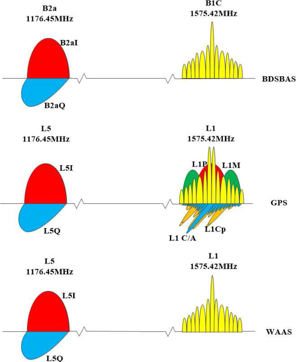
Fig. 1 Signals distribution of BDSBAS and GPS/WAAS.
Download figure:
Standard imageFrom the figure we can see that in L1/B1C band, signals overlapping with BDSBAS B1C include GPS L1 C/A, L1P, L1M and L1C, and WAAS L1. In L5/B2a band, signals overlapping with BDSBAS B2a include GPS L5C and WAAS L5.
3. The Computation of SSC
3.1. Mathematical Model
Note  is normalized (to unity over the transmission bandwidth) two-sided power spectral density (W Hz−1) at frequency f (Hz) of the desired signal (International Telecommunication Union 2011):
where BT is transmitting bandwidth, and Gx (f) is normalized two-sided power spectral density of desired signal with unlimited bandwidth.
Note  is normalized (to unity over the transmission bandwidth) two-sided power spectral density (W Hz−1) at frequency f (Hz) of the n-th interfering signal from the m-th satellite in a constellation:
where Gm,n (f) is normalized power spectral density of interfering signal with unlimited bandwidth.
Thus, the spectral separation coefficient (SSC) β of an interfering signal form the n-th signal of the m-th satellite to a desired signal, can be defined as:
3.2. Simulation Results
Signal characteristics for the BDSBAS signals in the 1559 MHz to 1610 MHz are detailed in Table 2.
Table 2. Characteristics of BDSBAS Signals in 1559 MHz to 1610 MHz
| Parameter | BDSBAS B1C |
|---|---|
| Reference | |
| Modulation | BPSK(1) |
| Chip Rate (Mcps) | 1.023 |
| Navigation Data Bit Rate (bps) | 250 |
| Symbol Rate (sps) | 500 |
| System | |
| Carrier Frequency (MHz) | 1575.42 |
| Transmit Bandwidth (MHz) | 2.046 |
| Minimum Received total Signal Power (dBW) | –160.2 |
| Maximum Aggregate Gain to BDSBAS Reference Receiver Antenna (dB) | 3 GEO: 4.6 |
Signal characteristics for the BDSBAS signals in the 1164 MHz to 1300 MHz are detailed in Table 3.
Table 3. Characteristics of BDSBAS Signals in 1164 MHz to 1300 MHz
| Parameter | BDSBAS B2a-d | BDSBAS B2a-p | |
|---|---|---|---|
| Reference | |||
| Modulation | QPSK(10) | ||
| Chip Rate (Mcps) | 10.23 | ||
| Navigation Data Bit Rate (bps) | 250 | No Data | |
| Symbol Rate (sps) | 500 | No Data | |
| System | |||
| Carrier Frequency (MHz) | 1176.45 | ||
| Transmit Bandwidth (MHz) | 20.46 | ||
| Minimum Received total Signal Power (dBW) | –156.5 | ||
| Maximum Aggregate Gain to BDSBAS Reference Receiver Antenna (dB) | 3GEO: 4.6 | ||
Transit bandwidth of GPS and WAAS refer to Annex-08 GPS RAD for Coordination with China 20100930 -A4, which for L1 band is 30.69 MHz and for L5 band is 24 MHz. The receive bandwidth is the same with transit bandwidth.
Thus, the SSC in L1/B1C and L5/B2a is calculated as shown in Tables 4 and 5.
Table 4. The SSC in L1/B1C Band*
| SSC(1/Hz) | Desired signal | BDSBAS B1C | GPS L1C/A | GPS L1P(Y) | GPS L1M | GPS L1C | WAAS L1 |
|---|---|---|---|---|---|---|---|
| Interfering signal | (TX|TX/RX) | 2.046/2.046 | 30.69/30.69 | 30.69/30.69 | 30.69/30.69 | 30.69/30.69 | 30.69/30.69 |
| (BDSBAS B1C) | 2.046 | –60.9845 | –61.3991 | –69.8047 | –92.0039 | –67.8107 | –61.3991 |
| (GPS L1C/A) | 30.69 | –61.3991 | –61.8008 | –69.9067 | –87.0636 | –68.0983 | –61.8008 |
| GPS L1P(Y) | 30.69 | –69.8047 | –69.9067 | –71.2452 | –79.7935 | –70.3927 | –69.9067 |
| GPS L1M | 30.69 | –92.0039 | –87.0636 | –79.7935 | –71.5584 | –81.9152 | –87.0636 |
| GPS L1C | 30.69 | –67.8107 | –68.0983 | –70.3927 | –81.9152 | –65.3482 | –68.0983 |
| WAAS L1 | 30.69 | –61.3991 | –61.8008 | –69.9067 | –87.0636 | –68.0983 | –61.8008 |
Notes: GPS L1C was computed by MBOC.
Table 5. The SSC in L5/B2a Band*
| SSC(1/Hz) | Desired signal | BDSBAS B2a | GPS L5C | WASS L5 |
|---|---|---|---|---|
| Interfering signal | (TX|TX/RX) | 20.46/20.46 | 24/24 | 24/24 |
| BDSBAS B2a | 20.46 | –70.9845 | –70.9968 | –70.9968 |
| GPS L5C | 24 | –70.9968 | –71.0089 | –71.0089 |
| WAAS L5C | 24 | –70.9968 | –71.0089 | –71.0089 |
BDSBAS B2a was only computed by the pilot channel.
4. Received Power of BDSBAS Satellites
4.1. Reference Assumption
The transmit power of BDSBAS L1/B1C and L5/B2a is supposed to be 14.1 dB and 13.3 dB respectively. BDSBAS representative gain patterns are provided in Table 6, which are under the assumption of rotational symmetry (European Document 2004). The values shown are nominal mean values over azimuth. The transmit power and nominal transmit antenna gain data of BDSBAS are provided for use in assessments of RF compatibility, and this does not represent a specification of BDSBAS antenna performance.
Table 6. BDSBAS Satellite Earth-Coverage Antenna Gain
| Off-Bore sight Angle (deg) | GEO Gain (dBic) | |
|---|---|---|
| BDSBAS B1C | BDSBAS B2a | |
| 0 | 14.2 | 13.4 |
| 1 | 14.2 | 13.4 |
| 2 | 14.2 | 13.5 |
| 3 | 14.3 | 13.6 |
| 4 | 14.4 | 13.7 |
| 5 | 14.4 | 13.9 |
| 6 | 14.5 | 14.1 |
| 7 | 14.5 | 14.2 |
| 8 | 14.5 | 14.4 |
| 9 | 14.4 | 14.5 |
| 10 | 14.3 | 14.5 |
| 11 | 14.0 | 14.6 |
| 12 | 13.6 | 14.5 |
| 13 | 13.1 | 14.4 |
| 14 | 12.5 | 14.2 |
| 15 | 11.8 | 14 |
The BDSBAS reference receiver antenna gain pattern is provided in Table 7.
Table 7. Nominal BDSBAS Receiver Antenna Gain Pattern
| Elevation Angle (deg) | Absolute Gain (dBic) |
|---|---|
| 0 | –7.0 |
| 5 | –5.5 |
| 10 | –3.4 |
| 15 | –2.0 |
| 20 | –1.2 |
| 25 | –0.9 |
| 30 | –0.8 |
| 35 | –0.8 |
| 40 | –0.8 |
| 45 | –0.7 |
| 50 | –0.7 |
| 55 | –0.5 |
| 60 | –0.5 |
| 65 | –0.5 |
| 70 | –0.5 |
| 75 | 0.0 |
| 80 | 0.0 |
| 85 | 0.0 |
| 90 | 0.0 |
4.2. BDSBAS Received Power
4.2.1. B1 band
By setting simulation duration as one day, calculation step as 300 s, mesh resolution as 5°, only free space loss is considered, maximum received powers of single satellite and constellation of BDSBAS B1C band are –159.1446 dBW and –154.7569 dBW respectively, as shown in Figures 2 and 3.
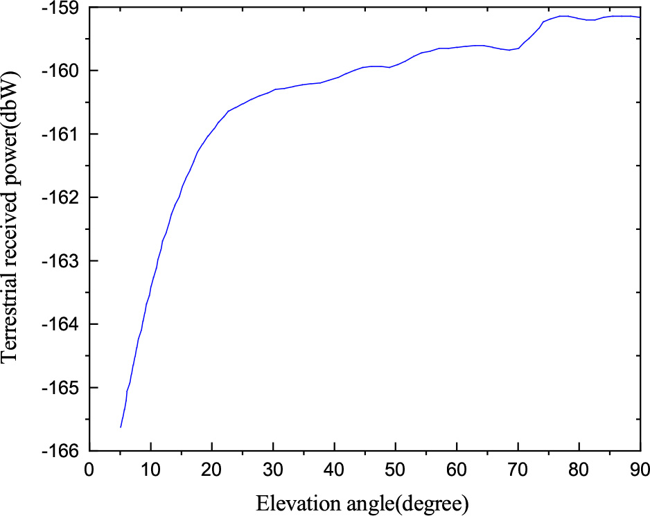
Fig. 2 Maximum received signal power of BDSBAS single satellite (B1).
Download figure:
Standard image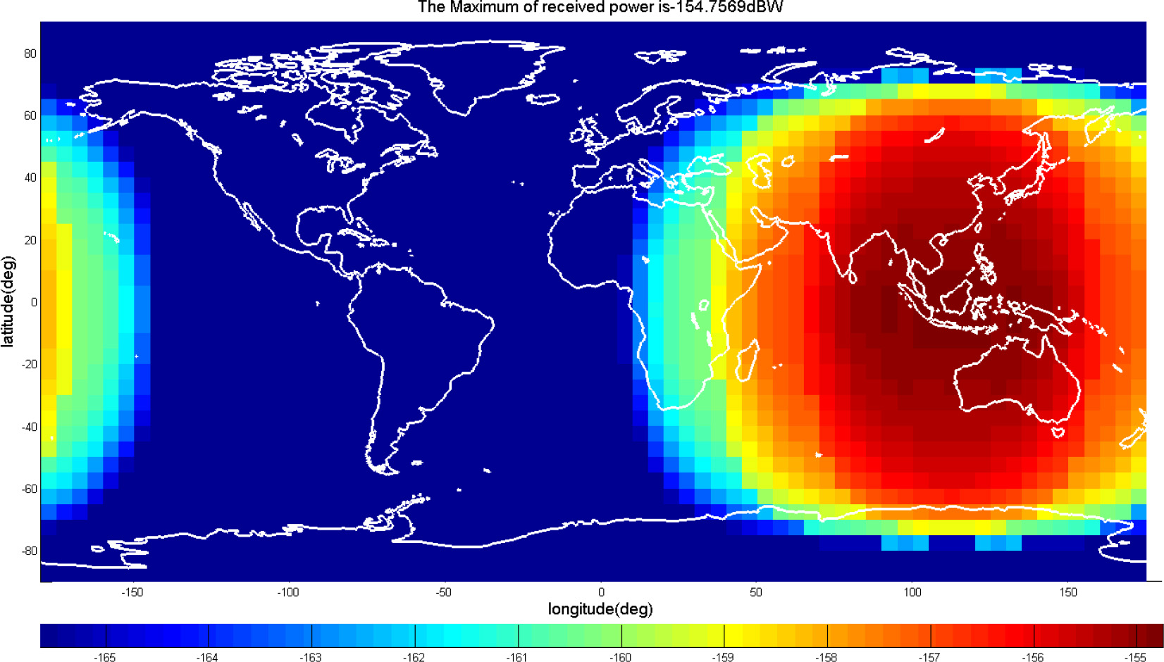
Fig. 3 Maximum received signal power of BDSBAS constellation (B1).
Download figure:
Standard imageThe coverage area of WAAS L1 is shown in Figure 4, whose maximum received power is –150.8772 dBW, and satellite obits are 107° W and 133° W (FAA 2008).
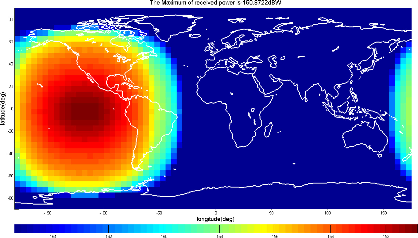
Fig. 4 Maximum received signal power of WAAS L1.
Download figure:
Standard imageThus, the overlapping area of BDSBAS B1 and WAAS L1 can be seen in Figure 5. In the overlapping area, the maximum number of BDSBAS visible satellites is 3, and the maximum receiving power of BDSBAS single satellite is –156.3225 dBW.

Fig. 5 Overlapping area of BDSBAS B1 and WAAS L1.
Download figure:
Standard image4.2.2. B2 band
By setting the same simulation duration as above, similarly the maximum received powers of single satellite and constellation of BDSBAS B2a band can be obtained by –158.1237 dBW and –153.6332 dBW respectively, as shown in Figure 6 and Figure 7.

Fig. 6 Maximum received signal power of BDSBAS single satellite (B2).
Download figure:
Standard image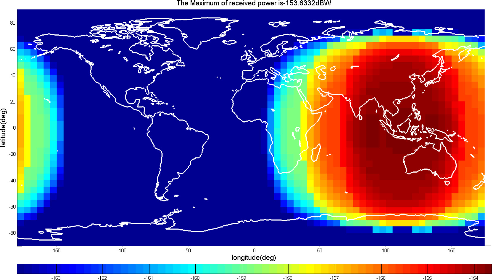
Fig. 7 Maximum received signal power of BDSBAS constellation (B2).
Download figure:
Standard imageThe coverage area of WAAS L5 is shown in Figure 8, which its maximum received power is –147.4334 dBW.

Fig. 8 Maximum received signal power of WAAS L5.
Download figure:
Standard imageThus, the overlapping area of BDSBAS B2 and WAAS L5 can be seen in Figure 9. In the overlapping area, the maximum number of BDSBAS visible satellites is 3, and the maximum receiving power of BDSBAS single satellite is –155.0322 dBW.
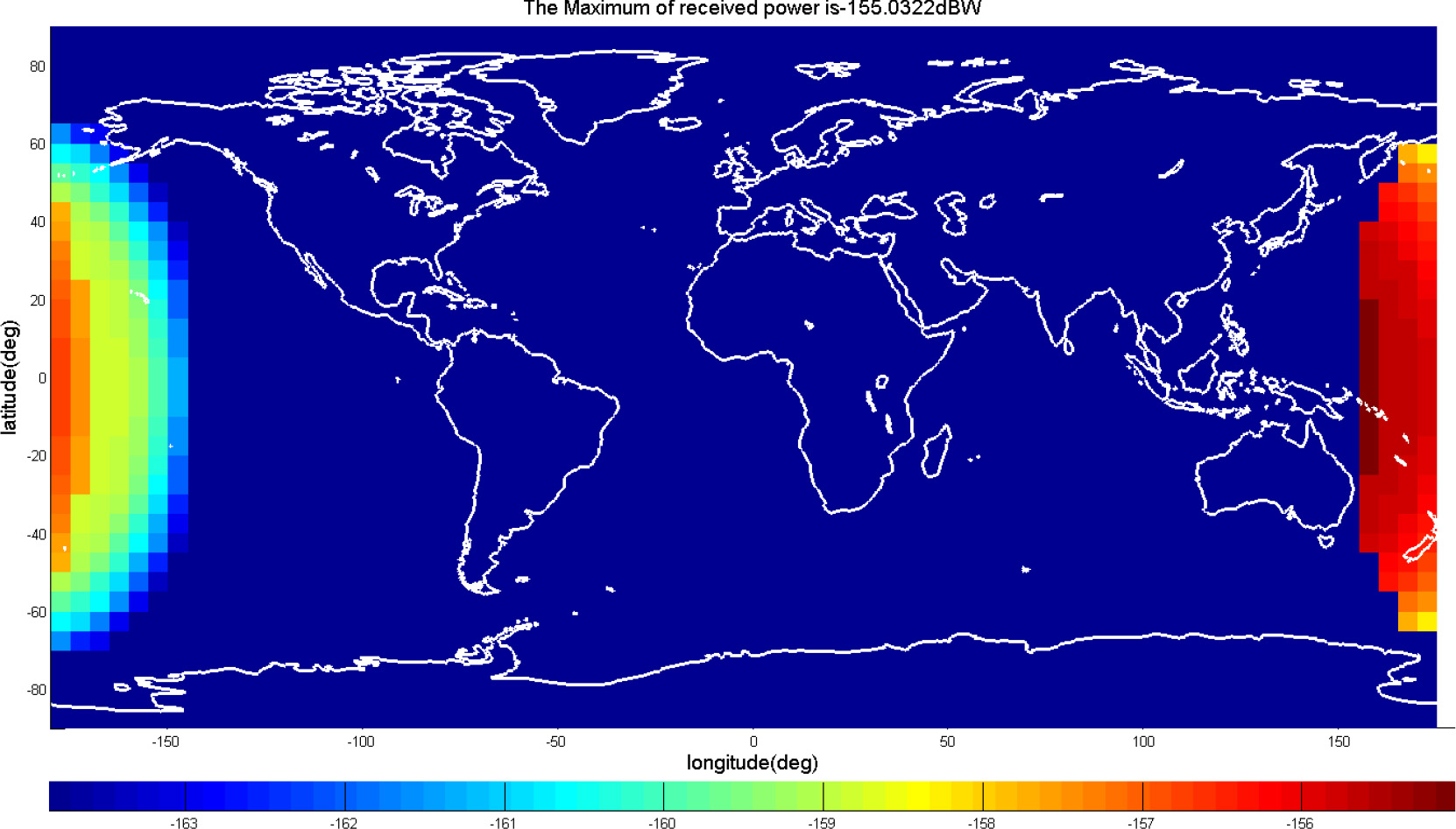
Fig. 9 Overlapping area of BDSBAS B2 and WAAS L5.
Download figure:
Standard image5. System Interference Analysis
5.1. Mathematical Model
ITU-R M.1831 adopts equivalent carrier-to-noise ratio  as the assessment parameter of system interference (International Telecommunication Union 2015). The reducing of
  can be used to analysis the effect of interference on receiver. System interference includes the intra-system and inter-system interference of navigation satellite systems, and also includes the artificial and non-artificial interference.
 has the following form:
where N0 is the power spectrum density of thermal noise of receiver pre-correlator. ν is the effective thermal noise power, which makes the value of  minimize while ν = 1. Iref, Iint and Iext are post-correlator effective white-noise power spectral-density due to the aggregate interference from all the signals transmitted by desired RNSS satellites (GPS/WAAS) in view, other RNSS satellites (BDSBAS) in view and non-RNSS satellites in view respectively. They can be calculated by following formula (Jun 2011; Titus B. M. & J. 2003):
In order to calculate the raise of correlator noise, all the signals which overlay the desired signal spectrum in the band need to be considered, including all the interference constellations. Thus, the equivalent white noise power spectrum density caused by Iref, Iint and Iext can be expressed as:
where n is the interference signal number of single satellite, and m is the satellites number of constellation.  ,
,  and
and  are the maximum powers of received interference signals.
  ,
,  and
and  are the receiving and processing losses of interference signals.
Consider the carrier-to-noise ratio decrease as the analysis index of interference effect of systems, note the intra-system interference caused by the overlapping of desired signal as Δ(C/N0)intra, and note the inter-system interference caused by the overlapping of desired signal as Δ(C/N0)inter. Ignore the interference from non-RNSS constellation, Δ(C/N0)intra and Δ(C/N0)inter can be expressed respectively as follows:
Equations (11) and (12) can be expressed in decibel form as follows:
To simplify the calculation, define the aggregate gain factor Gagg as the maximum received power ratio of a constellation and a single satellite, that is (International Telecommunication Union 2015; Q. 2015):
where Pm,max is the maximum received power of the interference signal n. The factor Gagg can be obtained by simulation, which taking position and antenna gain of receiver, and transmit power and radiation pattern of satellite into account, that is:
where Tm is the transmit power of satellite m; Gm,ant is the antenna gain of satellite m; Grec is the receiver gain; Lm, dist is the space loss, which can be calculated by the distance between satellite m and user receiver; Lm,atm is the atmospheric loss of RF transmission; Lm,pol is the user receiver antenna polarization mismatch loss.
Using the factor Gagg can reduce the repeated calculation of the satellite-to-earth RF link, thus Equation (8) and Equation (9) can be expressed as follows:
5.2. Interference Impact of BDSBAS
Using the formulas above, the intra-system interference between GPS/WAAS and inter-system interference between BDSBAS and GPS/WAAS can be calculated, thus the carrier-to-noise ratio decrease of GPS/WAAS caused by BDSBAS can be analyzed. Simulation results are shown in Table 8, where  is the aggregate gain factor, βn
is the SSC, and
is the aggregate gain factor, βn
is the SSC, and  is the maximum receiver power of interfering signal.
Table 8. Interference on GPS/WAAS L1/L5 Bands Caused by BDSBAS
| Desired signal | Non interfering condition | Iref | Iint | |||||||||||||
| GPS L1C/A} | 43dB-Hz | GPS L1C/A | GPS L1P(Y) | GPS L1M | GPS L1C | B1C | ||||||||||

| βn |

|

| βn |

|

| βn |

|

| βn |

|

| βn |

| ||
| 13.4 | -61.8 | -153 | 13.4 | -69.9 | -150 | 10.9 | -87.1 | -142 | 13.4 | -68.1 | -152 | 4.4 | -61.4 | -157.6 | ||
| 38.747dB-Hz (4.253dB lower than 43dB-Hz) | 38.668dB-Hz (0.079dB lower than 38.747dB-Hz) | |||||||||||||||
| GPS L1P(Y) | 40dB-Hz | GPS L1C/A | GPS L1P(Y) | GPS L1M | GPS L1C | B1C | ||||||||||

| βn |

|

| βn |

|

| βn |

|

| βn |

|

| βn |

| ||
| 13.4 | -69.9 | -153 | 13.4 | -71.2 | -150 | 10.9 | -79.8 | -142 | 13.4 | -70.4 | -152 | 4.4 | -69.8 | -157.6 | ||
| 37.738dB-Hz (2.262 lower than 40dB-Hz) | 37.720dB-Hz (0.018dB lower than 37.738 dB-Hz) | |||||||||||||||
| GPS L1M) | 43.5dB-Hz | GPS L1C/A | GPS L1P(Y) | GPS L1M | GPS L1C | B1C | ||||||||||

| βn |

|

| βn |

|

| βn |

|

| βn |

|

| βn |

| ||
| 13.4 | -87.1 | -153 | 13.4 | -79.8 | -150 | 10.9 | -71.6 | -142 | 13.4 | -81.9 | -152 | 4.4 | -92.0 | -157.6 | ||
| 40.914dB-Hz (2.586dB lower than 43.5dB-Hz) | 40.914dB-Hz (0dB lower than 40.914dB-Hz) | |||||||||||||||
| GPS L1C) | 44.5dB-Hz | GPS L1C/A | GPS L1P(Y) | GPS L1M | GPS L1C | B1C | ||||||||||

| βn |

|

| βn |

|

| βn |

|

| βn |

|

| βn |

| ||
| 13.4 | -67.8 | -153 | 13.4 | -70.2 | -150 | 10.9 | -82.2 | -142 | 13.4 | -65.3 | -152 | 4.4 | -67.5 | -157.6 | ||
| 41.092dB-Hz (3.409dB lower than 44.5dB-Hz) | 41.068dB-Hz (0.024dB lower than 41.092dB-Hz) | |||||||||||||||
| WAAS L1) | 43dB-Hz | WAAS L1 | N/A | N/A | N/A | B1C | ||||||||||

| βn |

| - | - | - | - | - | - | - | - | - |

| βn |

| ||
| 2.5 | –61.8 | –153 | - | - | - | - | - | - | - | - | - | 3.3 | –61.4 | –157.6 | ||
| 42.615dB-Hz (0.385dB lower than 43dB-Hz) | 42.467dB-Hz (0.148dB lower than 42.615dB-Hz) | |||||||||||||||
| GPS L5C) | 46.6dB-Hz | GPS L5C | N/A | N/A | N/A | B2a-p | ||||||||||

| βn |

| - | - | - | - | - | - | - | - | - |

| βn |

| ||
| 12.4 | -71.0 | -148 | - | - | - | - | - | - | - | - | - | 4.5 | -71.0 | -154.1 | ||
| 45.433dB-Hz (1.167dB lower than 46.6dB-Hz) | 45.392dB-Hz (0.041dB lower tha\\45.433dB-Hz) | |||||||||||||||
| WAAS L5) | 44.5dB-Hz | WAAS L5 | N/A | N/A | N/A | B2a-p | ||||||||||

| βn |

| - | - | - | - | - | - | - | - | - |

| βn |

| ||
| 2.6 | -71.0 | -151 | - | - | - | - | - | - | - | - | - | 3.4 | -71.0 | -154.1 | ||
| 44.431dB (0.069dB lower than 44.5dB-Hz) | 44.390dB-Hz (0.041dB lower than 44.431dB-Hz) | |||||||||||||||
Notes: (1) The power spectral density of noise is taken as –201.5dBW. (2) No consideration of reception loss. (3) GPS L1C was computed by MBOC modulation. (4) BDSBAS B2a was only computed by pilot channel.
According to the results above (see Table 8), we can see that the reduction of carrier-to-noise ratio of GPS/WAAS L1 and L5 signals caused by BDSBAS B1C and B2a signals is extremely low, and generally far less than the reduction of carrier-to-noise radio caused by intra-system interference of GPS/WAAS. Thus, BDSBAS would not cause the degradation in performance of GPS/WAAS.
In fact, GPS/WAAS L1C/A and L5 signals will also cause the radio interference to BDSBAS. Since GPS is a globally evenly distributed satellite constellation, its interference to BDSBAS is basically equivalent to its own intra-system interference; and the interference of WAAS to BDSBAS is basically the same as that of BDSBAS to WAAS (both of them are systems composed of 3GEO satellites). In the design and allocation of satellite EIRP (equivalent isotropic radiated power), BDSBAS has fully considered the above factors to ensure that the landing power of L1C/A and L5 signals meets the ICAO standards (which is greater than –160.5 dBW for L1C/A and is greater than –158.5 dBW for L5), and provide reliable SBAS aviation augmentation services.
6. Summary
Radio frequency signal compatibility and non-mutual-harm influence are the important basis of SBAS interoperability and joint integrity service for international aviation navigation. At present, under the ICAO framework, SBASs are jointly carrying out study and formulate of DFMC standards. In the future, SBAS will provide single frequency SBAS service on GPS L1 band and DFMC SBAS service on GPS L5 band.
According to ITU Proposal and BDSBAS reference assumptions, the paper made theoretical analysis and simulation of signal compatibility of BDSBAS and GPS/WAAS on L1/B1C and L5/B2a bands. The results show that BDSBAS causes slight decrease in signal performance on GPS/WAAS on L1 and L5 bands. Good compatibility is also seen between signals, which is the foundation of positive interoperability.
In the future, BDSBAS will continue conduct system construction work and provide integrity service according to the standard and requirement of international organizations such as ICAO and ITU, etc.
Acknowledgements
This work was supported in part by the National Natural Science Foundation of China (Grant Nos. 42074044 and 41974041) and in part by "Young Talent Lifting Project" of China Association for Science and Technology (Grant No. 2019QNRC001).