
Abstract
A Q-band two-beam cryogenic receiver for the Tianma Radio Telescope (TMRT) has been developed, and it uses the independently-developed key microwave and millimeter-wave components operating from 35 to 50GHz with a fractional bandwidth of 35%. The Q-band receiver consists of three parts: optics, cold unit assembly and warm unit assembly, and it can receive simultaneously the left-handed and right-handed circularly polarized waves. The cold unit assembly of each beam is composed of a feed horn, a noise injection coupler, a differential phase shifter, an orthomode transducer and two low-noise amplifiers, and it works at a temperature range near 20 K to greatly improve the detection sensitivity of the receiving system. The warm unit assembly includes four radio-frequency amplifiers, four radio-frequency high-pass filters, four waveguide biased mixers, four 4–12 GHz intermediate-frequency amplifiers and one 31–38 GHz frequency synthesizer. The measured Q-band four-channel receiver noise temperatures are roughly 30–40 K. In addition, the single-dish spectral line and international very long baseline interferometry (VLBI) observations between the TMRT and East Asia VLBI Network at the Q-band have been successfully carried out, demonstrating the advantages of the TMRT equipped with the state-of-the-art Q-band receiver.
Export citation and abstract BibTeX RIS
1. Introduction
The Tianma Radio Telescope (TMRT) is a newly-built 65m diameter fully-steerable instrument located in a western suburb of Shanghai, China. The objective of the highest frequency for the telescope is 50GHz. Phase I of project construction was completed in December 2013. As the key parts of the radio telescope, four cryogenic receivers covering the frequency ranges 1.33–1.73GHz, 2.2–2.4 GHz, 4.0–8.0GHz and 8.2–9.0GHz, respectively, are available (Yan et al. 2015; Li et al. 2016). The telescope has an active surface control utilizing actuators to compensate for gravity deformation in the main reflector during observations. To fulfill the highest frequency observation window of the TMRT, the microwave and millimeter-wave key components for the Q-band receiver were developed during 2013–2016, and they include feed horns, noise injection couplers, differential phase shifters (DPSs), orthomode transducers (OMTs) and 4–12GHz intermediate frequency (IF) amplifiers. By the second-quarter of 2016, four high frequency cryogenic receivers covering the frequency ranges 12.0–18.0 GHz (Li et al. 2016), 18.0–26.5 GHz, 30.0–34.0 GHz and 35.0–50.0 GHz had been installed on the telescope.
The Q-band receiver can be used for mapping massive star forming regions in the Milky Way with dense gas tracers, i.e. CS J=1–0 at the rest frequency of 48.990 GHz and HC3N J=5–4 at the rest frequency of 45.490 GHz, to study dense gas properties and star formation in these molecular clouds, as well as using CS J=1–0 and HC3N J = 5–4 as dense gas tracers to study star formation trends in galaxies (Gao & Solomon 2004). SiO J = 1–0 (v = 0) at the rest frequency of 43.423 GHz can also be used to study shocked gas in molecular clouds. It will double mapping speed with a two-beam system, while it can also double the effective on-source time with the nodding mode for observing point sources.
In this paper, the TMRT Q-band two-beam cryogenic receiver is presented. In Section 2, Q-band receiver system configurations worldwide are compared with the TMRT Q-band receiver diagram. The designs of optics and feed horn, cold unit assembly (CUA) and warm unit assembly (WUA) are introduced in Sections 3, 4 and 5 respectively. The laboratory test results and characteristics of the telescope including preliminary spectral line and international very long baseline interferometry (VLBI) observations are also provided in Section 6. Finally, a brief summary is given in Section 7.
2. Q-Band Receiver Technology and Diagram
Around the world, there is a variety of radio astronomy Q-band cryogenic receivers, which have been installed on radio telescopes or developed in laboratories (Wollack & Srikanth 1995; Anderson 2007; Perley et al. 2009; Lee et al. 2011; Guzmán 2013; Tsuboi et al. 2000; Nakamura et al. 2015). Detailed information on international Q-band cryogenic receivers is shown in Table 1. Only the Nobeyama 45m Telescope (Tsuboi et al. 2000) employs superconductor-insulator-superconductor (SIS) technology. All the others including the new receiver Z45 (Nakamura et al. 2015) on the Nobeyama 45m Telescope use or are going to utilize High-Electron- Mobility-Transistor (HEMT) technology. The TMRT Qband two-beam cryogenic receiver configuration follows the traditional design of low frequency bands. A schematic diagram of the receiver is depicted in Figure 1, which consists of three subsystems: optics, CUA and WUA. The receiver configuration has been optimized and reviewed several times since the project was approved in 2013. The radio signals are received by the feed horn, and then are separated into left-handed circular polarization (LCP) and right-handed circular polarization (RCP) signals by the DPS and OMT. After that, the received signals are amplified by the LNAs to enhance the signal-to-noise ratio (SNR). The coupler is used to inject the noise source to do system calibration. A downconverter module, including a room-temperature waveguide biased mixer and a radio-frequency (RF) highpass filter (HPF), is used in each polarization channel. The phase-locked oscillator with high output power of +17 dBm is divided in four paths to be used as local oscillators for four mixers. Therefore, the facility features a fixed IF band from 4 to 12GHz, which has a constant 8GHz bandwidth for simultaneous astronomical observation. The IF band is outputted from a down-converter module where the RF band is from 35 to 50GHz and the phase locked oscillator is from 31 to 38GHz in steps of 1Hz. The four-channel 4–12GHz IF signals are transmitted to the observation room, roughly 400m away from the telescope, utilizing an RF-over-fiber link with low attenuation, compression and noise temperature contribution. In addition, a WR-22 standard waveguide diode noise source with injection through two circular waveguide couplers (Yuan et al. 2014) is used to calibrate the system noise temperatures of the four channels, including LCP and RCP.
Table 1. The Technical Specifications of Q-band Cryogenic Receivers on Radio Telescopes around the World
| Telescope | Frequency (GHz) | Technology | Trx (K) | Status | Reference |
|---|---|---|---|---|---|
| Nobeyama | 40.0–50.0 | SIS | 40 | Developed | Tsuboi et al. (2000) |
| Nobeyama | 42.0–46.0 | HEMT | 50 | Developed | Nakamura et al. (2015) |
| GBT | 38.2–49.8 | HEMT | 20–45 | Developed | Wollack & Srikanth (1995) |
| EVLA | 40.0–50.0 | HEMT | 48 | Developed | Perley et al. (2009) |
| ATCA | 30.0–50.0 | HEMT | 40 | Developed | Moorey et al. (2008) |
| KVN | 42.0–44.0 | HEMT | 50 | Developed | Lee et al. (2011) |
| Effelsberg | 41.0–49.7 | HEMT | 60–70 | Developed | Fuerst (2003) |
| QUIET | 36.0–44.0 | HEMT | 35 | Developed | Newburgh (2010) |
| Planck | 39.6–48.4 | HEMT | 16.6 | Developed | Bersanelli et al. (2010) |
| WMAP | 35.0–46.0 | HEMT | 59 | Developed | Jarosik et al. (2003) |
| ALMA | 35.0–50.0 | HEMT | 26–33 | Developing | Hwang et al. (2014) |
| SRT | 33.0–50.0 | HEMT | 40 | Developing | Prandoni et al. (2017) |
| TMRT | 35.0–50.0 | HEMT | 30–40 | This Work |
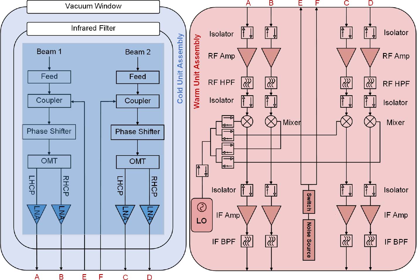
Fig. 1 A schematic diagram of the TMRT Q-band two-beam cryogenic receiver.
Download figure:
Standard image3. Optics and Feed Horn
The main TMRT requirement for Q-band receiver optics is the antenna aperture efficiency (Rudolf et al. 2007; Akgiray et al. 2013b) at the Cassegrain focus consisting of illumination, spillover, phase, cross-polarization and body-of-revolution-1 sub-efficiencies (Kildal 2015), which must be greater than 40% from 35 to 50GHz. Figure 2 shows the far-field pattern mapping of Q-band feeds in the focal plane of the TMRT with the feed spacing of 70 mm.
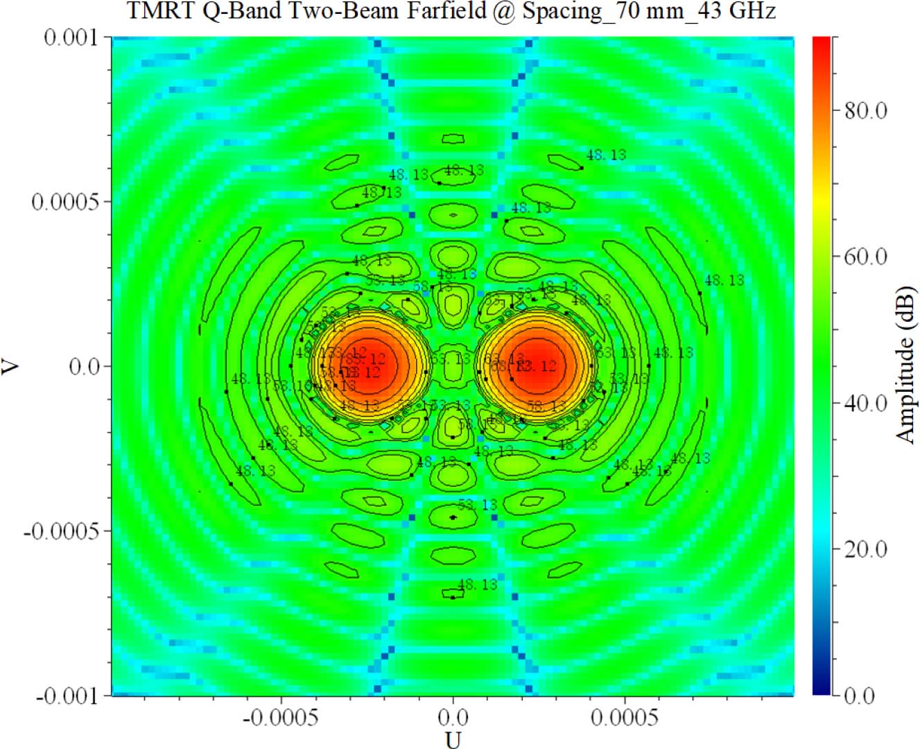
Fig. 2 Far-field pattern mapping of two feeds (D = 70 mm) with the unshaped 65 m Cassegrain reflector.
Download figure:
Standard imageIn view of the existing experiences of international focal-plane-array receivers, such as the Nobeyama 45m Telescope (Tsuboi et al. 2000), the Green Bank Telescope (GBT) (Wollack & Srikanth 1995; Norrod & Srikanth 1999), the Sardinia Radio Telescope (SRT) (Orfei et al. 2010) and scientific objectives of the TMRT, the physical distance of two feeds in the focal plane was determined to be 70mm, forming a roughly 100'' interval in the sky. The calculated aperture efficiency of the feed horn is more than 66% over the entire frequency band without inclusion of the root mean square (RMS) errors from reflector panels. These panels meet the aperture efficiency specification of 40% at Q-band.
The requirement of a feed on the radio telescope which has symmetric beam, low sidelobes and low cross polarization characteristics can be satisfied by a horn that creates linear electric fields. Corrugated horns (Thomas et al. 1986; Olver & Xiang 1988; McKay et al. 2013) are usually used as feeds in satellite communication and radio astronomy. These properties are typically obtained by coupling efficiently from the fundamental circular waveguide TE11 mode to the corrugated section HE11 hybrid mode with roughly a combination of 85% TE11 and 15% TM11. The mode converter section is one of the most difficult parts of the feed to design and optimize for return loss and efficiency. Any impedance mismatch between themodes in the circular waveguide and themodes in the throat section of the feed will excite higher-order modes. Profiled corrugated horns have the advantages of being short, compact and lightweight. In the TMRT Q-band receiver, a sine-profiled corrugated feed horn is selected to obtain a compact configuration of 130mm × 50 mm × 50 mm depicted in Figure 3. This corrugated horn employed a platelet fabrication process at low cost (Del Torto et al. 2011) to obtain the same outstanding performance as electroformed equivalents.
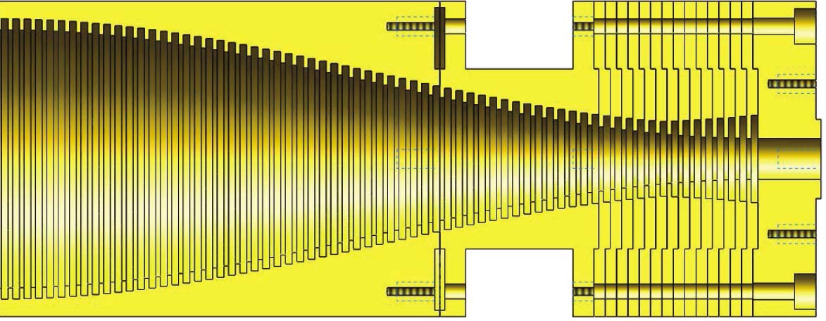
Fig. 3 A mechanical drawing of the Q-band corrugated feed horn through platelet fabrication techniques.
Download figure:
Standard imageAfter fabrication by copper materials using the platelet technique, excellent return loss of more than 20 dB at the output port of the feed was obtained, which agrees well with the simulation result shown in Figure 4. In addition, the insertion loss is roughly 0.1 dB via the total insertion loss of feed network subtracting the ones of noise injection coupler, DPS, OMT, etc. Far-field radiation patterns of the corrugated feed horn at 42.5GHz are also presented in Figure 5. The edge taper at the subtended half-angle of 13° is from −18 dB to −10 dB with an average value of −16.5 dB to achieve the optimal sensitivity.
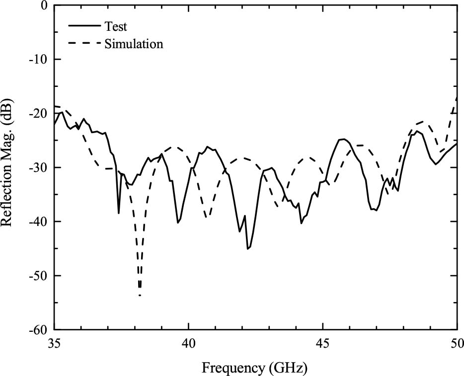
Fig. 4 Simulated and measured reflection of the feed horn.
Download figure:
Standard image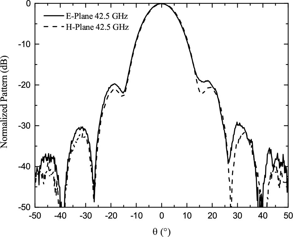
Fig. 5 Measured far-field patterns of the corrugated feed horn in ϕ = 0° and ϕ = 90° planes at 42.5 GHz.
Download figure:
Standard imageCryogenic radio astronomy receivers always have RF vacuum windows to propagate the signal to the feed network. An HDPE RF vacuum window with thickness of 15mm is adopted in front of feed horns. In order to decrease the reflection coefficient of the vacuumwindow, which is less than −15 dB, circular holes or grooves on two sides of the window are added. In addition, infrared filters between the RF vacuum window and feed network are required to avoid heat loading of the cryogenic components of the receiver. The filters should be opaque to infrared radiation while remaining highly transparent to microwaves and millimeter-waves, as well as being capable of operating at cryogenic temperatures, for example 77K in the Q-band receiver. Black polyethylene, Zitex and Fluorogold (Lamb 1993; Miao et al. 2015; Koller et al. 2006) have been proposed as such materials. In this receiver, Zitex was chosen to be the candidate operating at 77K. Four layers of Zitex with spacing of 1mm between different layers were finally used based on a tradeoff between insertion loss of the filter and physical temperature of the feed at 25K.
4. Cold Unit Assembly
The TMRT Q-band two-beam cryogenic receiver is an HEMT receiver, with a cryogenic low-noise amplifier (LNA) (Weinreb 1980; Akgiray et al. 2013a; Schleeh et al. 2013) employing gallium arsenide (GaAs) or indium phosphide (InP) HEMT technology. With the high gain cryogenic LNA in front of the mixer of the receiver, the noise contribution is mainly from the optics, vacuum window, infrared filter, feed network and LNA. Besides, unlike the SISmixer which needs a 4K operating temperature, the HEMT LNA achieves low noise performance in a temperature range of 15–20K.
The prototype of the TMRT Q-band two-beam CUA is shown in Figure 6. The key components in the CUA are the corrugated feed horn, noise injection coupler, differential phase shifter, OMT and cryogenic LNAs. The feed networks shown in Figure 7 are supported with several G-10 thermally-insulated brackets, and they operate in a temperature range around 20K via the cold copper straps from the second stage of the cold head. The cryogenic LNA of each polarization is directly connected to the output standard WR-22 waveguide port of the OMT. A combined waveguide tube is chosen to connect from the cryogenic LNA to the cryostat outer wall with a low heat transfer, and it consists of a 50mm length of copper and a 150mm length of stainless steel.
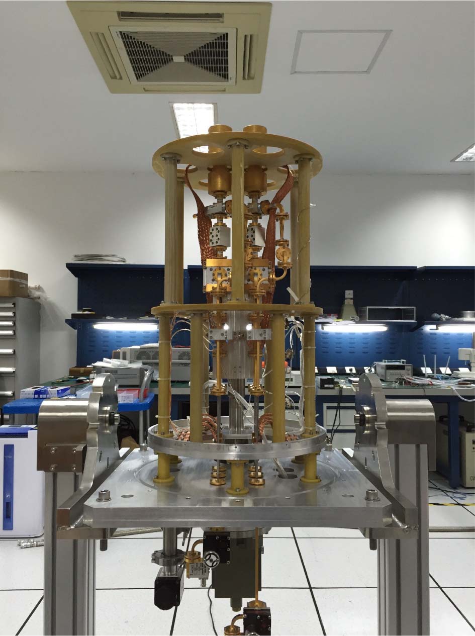
Fig. 6 TMRT Q-band two-beam CUA (Dimensions: 345 mm × 345 mm × 680 mm; Weight: 95 kg).
Download figure:
Standard image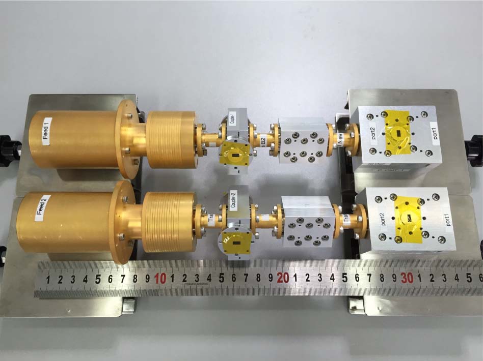
Fig. 7 TMRT Q-band two-beam feed network prototype: corrugated feed horn, noise injection coupler, DPS and OMT (from left to right).
Download figure:
Standard image4.1. Differential Phase Shifter
A waveguide DPS from 35 to 50GHz with an axial ratio less than 1 dB by CNC machining is presented. The purpose of the DPS core design is to provide the proper transformation between circularly polarized signals and corresponding linearly polarized signals. A wideband rectangular waveguide phase shifter with transverse corrugations on all four walls was introduced in Srikanth (1997), which has been successfully used in many cryogenic receivers. However, the electroforming process is usually needed for a four-wall corrugated phase shifter to ensure proper electrical performance, and it is high-cost to some extent. A configuration of the waveguide DPS used in the TMRT Q-band receiver is shown in Figure 8. The DPS is made of a square waveguide with one set of opposite walls loaded with corrugations and another set of smooth walls (Chung et al. 2010).

Fig. 8 Waveguide DPS with two-wall corrugations.
Download figure:
Standard imageMeasured return losses better than 17 dB from 35 to 50GHz for the two orthogonal polarizations including the adaptors are shown in Figure 9. The measured insertion losses for both orthogonal polarizations are less than 0.1 dB, as displayed in Figure 10 after subtracting the insertion losses of the four adaptors via the multiple tests and calibrations. The measured phase shift between two orthogonal modes is 90°±6°, corresponding to an axial ratio of 0.9 dB, depicted in Figure 11.

Fig. 9 Measured reflection at the DPS output ports.
Download figure:
Standard image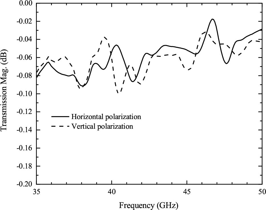
Fig. 10 Measured transmission of the DPS.
Download figure:
Standard image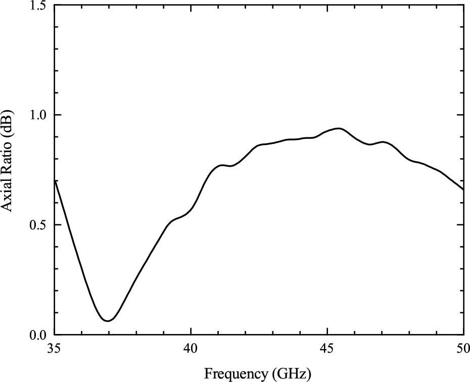
Fig. 11 Measured axial ratio of the DPS.
Download figure:
Standard image4.2. Orthomode Transducer
OMTs are critical passive components in radio astronomy receivers for simultaneously receiving orthogonally polarized radio waves (Coutts 2011; Henke & Claude 2014; Virone et al. 2014). A waveguide OMT generally consists of three physical ports, a common input port which can propagate two orthogonalmodes and two standard rectangular waveguide output ports, one for each polarization. The OMT is designed to have a compact configuration and for ease of fabrication, as shown in Figure 7.
A turnstile-junction OMT has been designed in Henke & Claude (2014) at the Q-band. However, this kind of configuration can easily generate spikes in receiver noise if the assembly alignment is not good. Figure 12 shows the overall diagram of the designed Boifot-junction double-ridge OMT (Kamikura et al. 2010). The input port of the device is a mode converter, which converts the input from a circular to a square waveguide propagating as the two orthogonal polarization modes. These orthogonal modes are separated by means of the Boifot-junction double-ridge structure. Vertical polarization goes forward via an E-Bend structure, while horizontal polarization is recombined by the Y-Junction configuration. The two outputs of the OMT are standard WR-22 waveguide ports for each orthogonal polarization. The component is measured using a Vector Network Analyzer model N5245A from Keysight Technologies. The measured insertion losses consisting of horizontal and vertical polarizations are less than 0.4 dB as shown in Figure 13, and measured return losses at the output ports are more than 20 dB as shown in Figure 14. Figure 15 displays the isolation between the two output ports of the OMT combined with the feed horn, the noise injection coupler and the DPS. This demonstrates that the LCP and RCP port isolation is more than 20 dB over the entire frequency band.
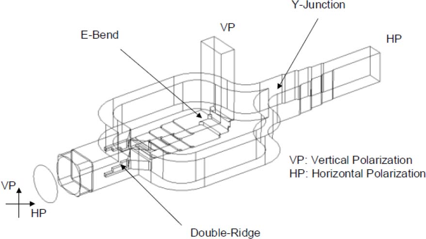
Fig. 12 Model of the Boifot-junction double-ridge OMT.
Download figure:
Standard image
Fig. 13 Measured transmission of the OMT.
Download figure:
Standard image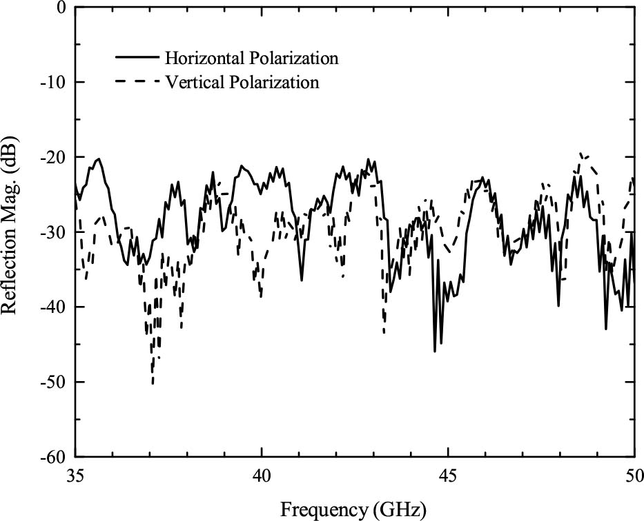
Fig. 14 Measured reflection of the OMT.
Download figure:
Standard image
Fig. 15 LCP and RCP isolation of the feed network at the output ports of the OMT.
Download figure:
Standard image4.3. Cryogenic Low-Noise Amplifier
The cryogenic LNA in our Q-band receiver is an ultralow noise cryogenic amplifier operating in 28–52GHz at 15K. The LNA is packaged in a standardWR-22 waveguide module with Nano-D DC power supply connectors and was provided by the Low Noise Factory (LNF) in Sweden. The dimensions of the gold-plated aluminum module are roughly 28.0 mm × 19.5 mm × 19.2 mm. The amplifier modules use monolithic microwave integrated circuit (MMIC) technology to ensure high reliability and uniformity of four receiving channels. The measured noise temperature of the cryogenic LNA at 10K is roughly 18–20K with gain of 28–30 dB. Due to the limited cryogenic test bench at LNF in 2014, only the cryogenic results up to 40GHz shown in Figure 16 were supplied.
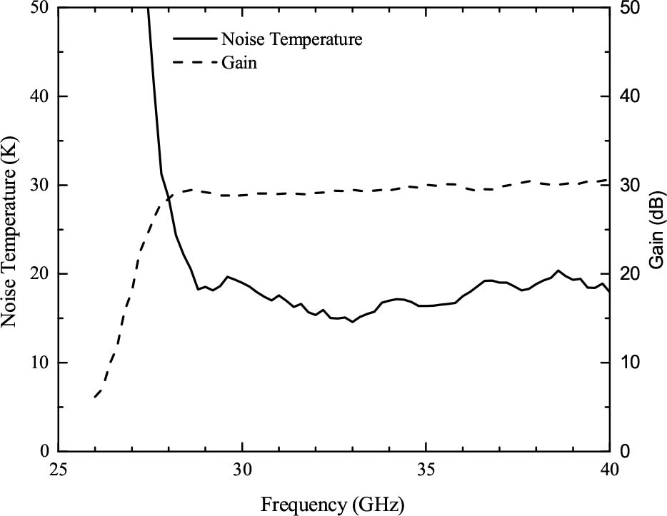
Fig. 16 Measured results of Q-band cryogenic LNA provided by LNF.
Download figure:
Standard image4.4. Vacuum Waveguide Feedthrough
The output of the cryogenic LNA is then connected to the homemade WR-22 vacuum waveguide feedthrough at room temperature. An RF-choke ring (Pozar 2011) is used to suppress the resonant frequency within the operating band. The detailed design layout is depicted in Figure 17. Mylar with a thickness of 100μm is used between the two standard WR-22 waveguides whose leakage rate does not exceed 1−10 cc s−1 of helium at 1 atm. Figure 18 presents comparisons of the different insertion losses between cases with an RF choke and without an RF choke.

Fig. 17 Vacuum waveguide feedthrough.
Download figure:
Standard image
Fig. 18 Transmission of the vacuum waveguide feedthrough with an RF choke and without an RF choke.
Download figure:
Standard image5. Warm Unit Assembly
Most of the TMRT Q-band two-beam receiver components are located in the WUA shown in Figure 19. The major function blocks in the WUA are four down-converter chains connected to the CUA, and a phased locked tuning oscillator. The down-converter chain incorporates the warmLNA, HPF, waveguide biasedmixer, etc., where the measured sideband rejection ratio of the HPF at 29.7GHz is more than 45 dB. The local oscillator uses the Hittite Microwave T2240 with a frequency range of 31–38GHz which can be remotely controlled by the LAN port. Each IF channel of theWUA is composed of a coaxial band-pass filter (BPF), a broadband coaxial isolator, and an IF amplifier. An IF amplifier which can provide a gain of at least 30 dB from 4 to 12GHz has also been successfully designed and fabricated (Zhang et al. 2016). Most of the TMRT Q-band two-beam receiver components are located in the WUA shown in Figure 19. The major function blocks in the WUA are four downconverter chains connected to the CUA, and a phased locked tuning oscillator. The down-converter chain incorporates the warmLNA, HPF, waveguide biasedmixer, etc., where the measured sideband rejection ratio of the HPF at 29.7GHz is more than 45 dB. The local oscillator uses the Hittite Microwave T2240 with a frequency range of 31–38GHz which can be remotely controlled by the LAN port. Each IF channel of theWUA is composed of a coaxial band-pass filter (BPF), a broadband coaxial isolator, and an IF amplifier. An IF amplifier which can provide a gain of at least 30 dB from 4 to 12GHz has also been successfully designed and fabricated (Zhang et al. 2016).
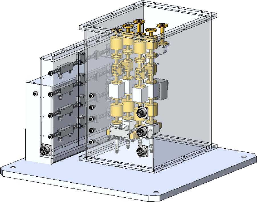
Fig. 19 Three-dimensional mechanical outline of TMRT Qband two-beam WUA.
Download figure:
Standard imageThe conversion gain test bench of the downconverter chain is shown in Figure 20. Due to excellent gain flatness of the warm RF LNA and IF LNA with smooth conversion loss of the waveguide biased mixer, the IF output gain flatness is within ±3 dB in any 2GHz bandwidth as shown in Figures 21–24. With the help of fixed coaxial attenuators, 1 dB power compression points referring to four-channel output ports of the receiver system are all above +10 dBm.
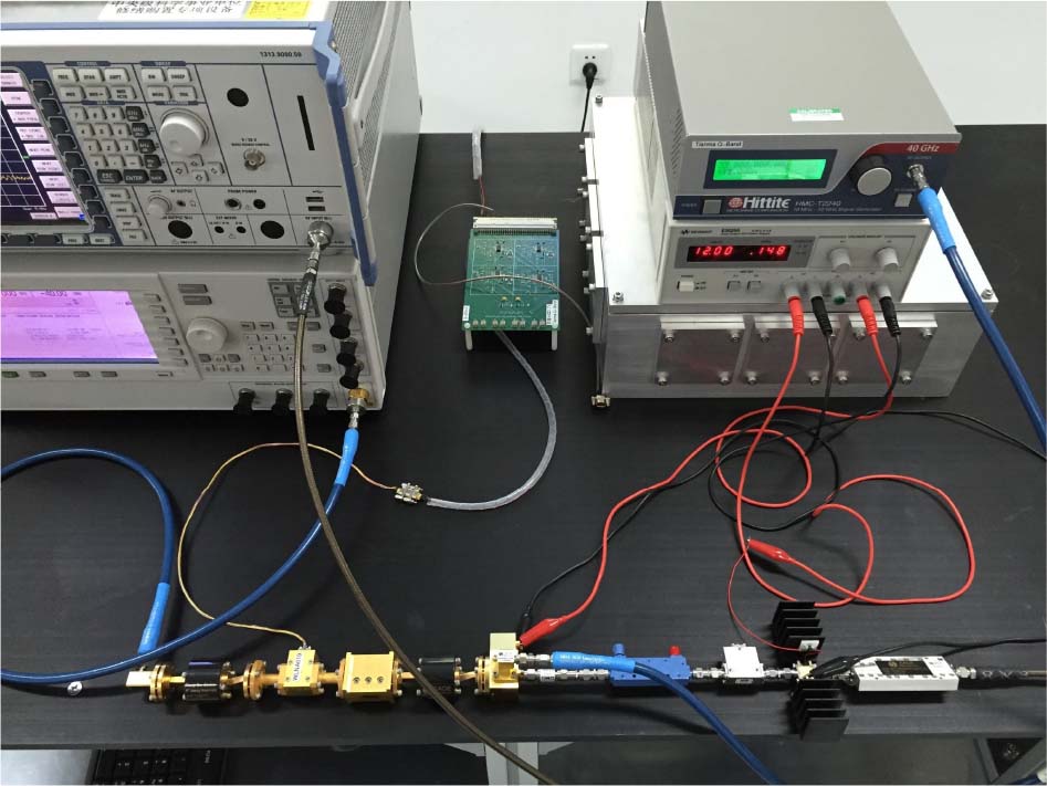
Fig. 20 Down-converter chain consisting of waveguide isolator, RF LNA, waveguide HPF, waveguide isolator, waveguide biased mixer, directional coupler, coaxial isolator, IF LNA and IF BPF (from left to right).
Download figure:
Standard image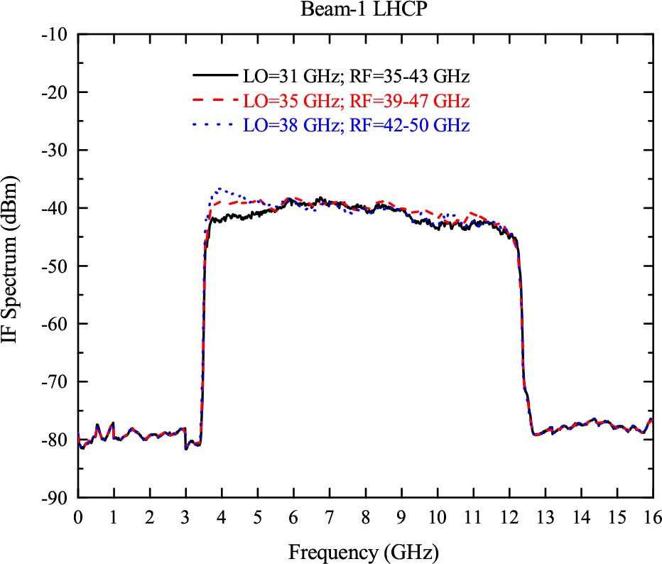
Fig. 21 IF output spectrum of the beam-1 LHCP channel.
Download figure:
Standard image
Fig. 22 IF output spectrum of the beam-1 RHCP channel.
Download figure:
Standard image
Fig. 23 IF output spectrum of the beam-2 LHCP channel.
Download figure:
Standard image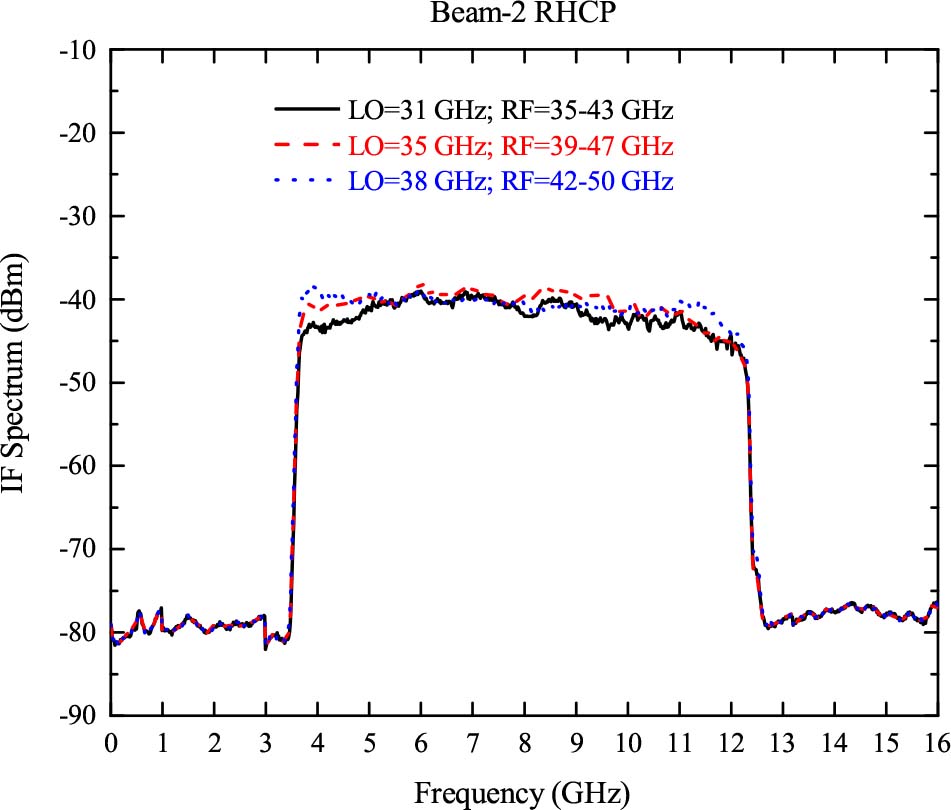
Fig. 24 IF output spectrum of the beam-2 RHCP channel.
Download figure:
Standard image6. Receiver Performance
The receiver noise temperature, power gain and dynamic range can be predicted from noise, gain and power compression point performances of the key components shown in Table 2. The gain and dynamic range of the CUA are mainly determined by the performance of cryogenic LNA due to the fact that the insertion losses of the passive components in front of the cryogenic LNA are generally no more than 1 dB. In our receiver, microwave components consisting of the feed network and cryogenic LNAs inside the cryostat are fixed, and the gain of the WUA is adjusted by adding fixed coaxial attenuators before and after the IF amplifier. This method has a negligible effect on the receiver noise temperature.
Table 2. Performance Prediction for the TMRT Q-band Receiver at 43 GHz
| Component | Pout (1 dB)(1) | Temperature(2) (K) | Gain(3) (dB) |  (K) (K) |
Δ T(5) (K) |  (K) (K) |
Total Gain(7) (dB) |
|---|---|---|---|---|---|---|---|
| Vacuum Window | 300 | –0.10 | 6.99 | 6.99 | |||
| Infrared Filter | 77 | –0.10 | 1.79 | 1.84 | |||
| Feed Horn | 20 | –0.10 | 0.47 | 0.49 | |||
| DPS+OMT | 20 | –0.50 | 2.44 | 2.61 | |||
| Cryo LNA | –10 | 20 | 26.00 | 18.00 | 21.64 | ||
| Copper WG | 20 | –0.10 | 0.47 | 0.00 | |||
| SS WG | 150 | –1.00 | 38.84 | 0.12 | |||
| WG Feedthru | 300 | –0.20 | 14.14 | 0.06 | 34 | 24 | |
| WG Isolator | 300 | –1.00 | 77.68 | 0.32 | |||
| RF Amplifier | 0 | 300 | 33.00 | 150.00 | 0.77 | ||
| HPF | 300 | –0.40 | 28.94 | 0.00 | |||
| WG Isolator | 300 | –1.00 | 77.68 | 0.00 | |||
| Mixer | 300 | –8.00 | 1592.87 | 0.01 | |||
| Attenuator | 300 | –6.00 | 894.32 | 0.02 | |||
| Coupler | 300 | –0.20 | 14.14 | 0.00 | |||
| Coax Isolator | 300 | –1.00 | 77.68 | 0.01 | |||
| Attenuator | 300 | –3.00 | 298.58 | 0.04 | |||
| IF Amplifier | +10 | 300 | 33.00 | 149.00 | 0.03 | ||
| Attenuator | 300 | –3.00 | 298.58 | 0.00 | |||
| BPF | 300 | –2.00 | 175.47 | 0.00 | 35 | 64 | |
| Attenuator | 300 | –6.00 | 894.32 | 0.00 | 58 |
Notes: (1) The output power 1 dB compression point; (2) The physical working temperature of the component; (3) The gain of the component; (4) The noise temperature of the component; (5) The cascaded noise temperature of the component in the system; (6) The receiver noise temperature (sum of ΔT(5)); (7) The receiver total gain (sum of Gain(3)).
As shown in Figure 25, the average noise temperatures of the receiver are roughly 30–40K using the liquid nitrogen and a warmmicrowave absorber. In addition, the interval of two beams in the sky is measured to be about 90'' (3–4 HPBWs). After the separate Y-factor measurements with a microwave absorber and cold sky, the four-channel system noise temperatures from 55 to 125K are shown in Figure 25. It is expected that the system noise temperature is increased at the high end of the operating frequency band due to the oxygen absorption line.
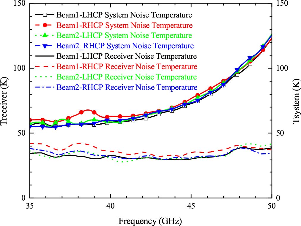
Fig. 25 Measured four-channel receiver and system noise temperatures.
Download figure:
Standard imageThe performance of the Q-band beam-2 at 43GHz was tested assuming atmospheric opacity in the zenith direction was τ0 = 0.1. The overall performance is shown in Figure 26. The extended out-of-focus technique is proposed for measurement of the gravitational deformation of the TMRT. Applying the gravitational model with the main-reflector surface accuracy of 0.27 mm RMS improves the aperture efficiency at both low and high elevations. In the case of the active surfacemodel, the aperture efficiency can reach more than 50%. The system noise temperature in the zenith direction, consisting of the sky, antenna ohmic loss, etc., is roughly 80K with the system equivalent flux density (SEFD) of about 120 Jy and the degrees per flux unit (DPFU) of 0.6K Jy−1. In a word, when the 65 m main-reflector active surface control system is turned on, all the Q-band electrical performances meet the required system specifications.
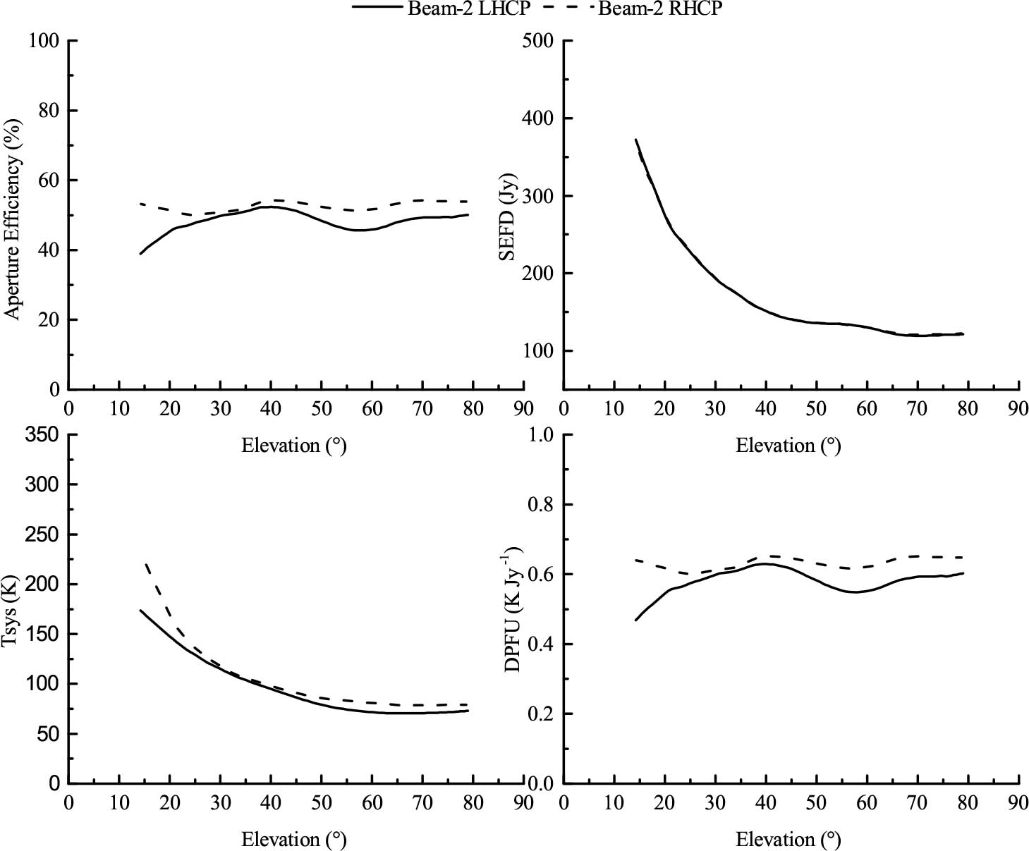
Fig. 26 TMRT Q-band beam-2 aperture efficiency, SEFD, system noise temperature and DPFU over elevation angles at 43 GHz.
Download figure:
Standard imageThe Q-band receiver, together with the digital backend system (DIBAS), was used to do spectroscopy observations in the winter of 2016–2017. Three independent IFs can be obtained simultaneously within 8GHz in the tuning range of the Q-band receiver. On-the-Fly (OTF) mode and standard position switching mode can be used. Figure 27 shows the velocity integrated map of one dense gas tracer: CS J = 1–0 at the rest frequency of 48.990GHz toward a massive star forming region G188.94+0.88, with about 40minutes of telescope time with the OTF mode. Based on the testing results of OTF mapping for these lines, the TMRT Q-band receiver provides a powerful tool for studying dense gas in Milky Way sources. In addition, the TMRT uses data processing to eliminate image rotation when making extended source mapping.

Fig. 27 Map of CS J=1−0 at the rest frequency of 48.990 GHz.
Download figure:
Standard imageSome international joint VLBI observations between the TMRT and the East Asia VLBI network at Q-band were successfully carried out in Spring 2017. The high sensitivity of the TMRT at Q-band can be seen from the high SNR of the VLBI fringe results shown in Figure 28. The TMRT will play a key role in the East Asian region for millimeter VLBI observations.

Fig. 28 VLBI fringe between TMRT and KVN-YS baseline at Q-band (source: 3C 273).
Download figure:
Standard image7. Conclusions
A Q-band two-beam cryogenic receiver for the TMRT has been built. The measured receiver noise temperatures for the four channels are roughly 30–40K with the system noise temperature of 55–125K. Several single-dish and VLBI observations have been successfully carried out with good results. It is believed that the TMRT will play an important role in astronomical observations.
The authors would like to thank Dr. SanderWeinreb, Director of theMicrowave Research Group at California Institute of Technology, Pasadena, CA, USA, for his kind revision and suggestions that helped improve the paper. This work was supported by the Special Fund for Astronomy from the Ministry of Finance, the National Natural Science Foundation of China (Nos. 11403080, 11590780 and 11590783), the Knowledge Innovation Programof the Chinese Academy of Sciences (No. KJCX1-YW-18), the Scientific Program of Shanghai Municipality (No. 08DZ1160100) and the Youth Innovation Promotion Association of Chinese Academy of Sciences (No. 2017315).