
Abstract
The magnetic anisotropy manipulation in the Sm3Fe5O12 (SmIG) films and its effect on the interfacial spin coupling in the CoFe/SmIG heterostructures were studied carefully. By switching the orientation of the Gd3Ga5O12 substrates from (111) to (001), the magnetic anisotropy of obtained SmIG films shifts from in-plane to out-of-plane. Similar results can also be obtained in the films on Gd3Sc2Ga3O12 substrates, which identifies the universality of such orientation-induced magnetic anisotropy switching. Additionally, the interfacial spin coupling and magnetic anisotropy switching effect on the spin wave in CoFe/SmIG magnetic heterojunctions have also been explored by utilizing the time-resolved magneto–optical Kerr effect technique. It is intriguing to find that both the frequency and effective damping factor of spin precession in CoFe/SmIG heterojunctions can be manipulated by the magnetic anisotropy switching of SmIG films. These findings not only provide a route for the perpendicular magnetic anisotropy acquisition but also give a further path for spin manipulation in magnetic films and heterojunctions.
Export citation and abstract BibTeX RIS
1. Introduction
Spin manipulation, which is the basis of the spintronic phenomenon, is of particular interest in magnetic systems owing to both fundamental and applied aspects.[1,2] As for magnetic films, switching the spin vectors between in-plane (IP) and out-of-plane (OP), i.e., magnetic anisotropy switching, is one of the most commonly controlled parameters. In particular, magnetic films with perpendicular magnetic anisotropy (PMA) have attracted great attention also from technological point of view due to low switching current and strong thermal stability, which enable it for high performance magnetic memory, logic devices, and other applications.[3–11] As for magnetic heterojunctions, the main target of spin manipulation shifts to the interfacial spin coupling between the layers. During the spintronic device working, the spin manipulation of heterojunction is achieved through external stimuli, such as magnetic field,[12] electric field,[13,14] and laser illumination.[15,16] However, it should be emphasized that the basis for effective external field manipulation is to understand the detailed coupling between magnetic layers in the heterojunction. Therefore, the interfacial spin controlling, such as the films' magnetic anisotropy effect on the interface, is the basis for the application of magnetic heterojunction devices.
Recently, rare-earth iron garnets (ReIGs) films and ReIGs-based magnetic heterojunctions have attracted great attention for their high frequency and fast switching of magnetic properties above room temperatures.[17–23] Among them, Y3Fe5O12 is one of the popular ferrimagnetic insulators with ultralow Gilbert damping (α ∼ 2 × 10⁻⁴), tunable magnetic anisotropy, and outstanding magneto–optical properties.[24–28] Besides, other ReIGs films with PMA have also been developed, such as Tm3Fe5O12,[29–31] Tb3Fe5O12,[12,32] Eu3Fe5O12,[32] and Ce- or Bi-substituted Y3Fe5O12.[33–36] In the ReIGs family, ferrimagnetic Sm3Fe5O12 (SmIG) has a larger lattice constant,[37] and it exhibits high dielectric permittivity[38] and low dielectric loss in a wide range of temperature and frequency,[39] which is quite attractive for high frequency applications. Moreover, SmIG has a large anisotropy with the anisotropy constants of K1: –1.2 × 10⁶ ergs/cm3 and K2: +1.0 × 10⁶ ergs/cm3 (at 80 K),[40,41] which provide routes for magnetic anisotropy regulation of SmIG film through the crystal lattice and epitaxial strain by changing the film thickness.[42] It has been predicted that (111)-oriented SmIG film may have PMA,[43] but there is no experimental evidence confirming its realization. Besides, there is very little research on the spin manipulation in the SmIGs-based magnetic heterojunctions though it is crucial for the SmIGs' future application in spintronic devices.
In this work, we demonstrate the crystal orientation-induced magnetic anisotropy manipulation of SmIG films at first. The easy magnetization axes of SmIG films shift from IP to OP direction with varying the Gd3Ga5O12 (GGG) substrates orientation from (111) to (001). Similar results can also be found in the films on Gd3Sc2Ga3O12 (GSGG) substrates. Furthermore, the magnetic anisotropy switching effect on the spin wave in CoFe/SmIG magnetic heterojunctions has also been explored by the time-resolved magneto–optical Kerr effect technique (TR-MOKE). It is interesting to find that both the frequency and effective damping factor of spin precession in CoFe/SmIG heterojunctions can be manipulated by the magnetic anisotropy switching of SmIG films.
2. Experimental details
The epitaxial SmIG thin films were fabricated on the GGG and GSGG substrates by pulsed laser deposition (PLD) technique. During the growth process, the substrate temperature was kept at 600 °C, the oxygen pressure was 5 Pa, and the distance between the substrate and the target was 5 cm. The density of the excimer laser beam (λ = 248 nm, 5 Hz) was about 1.5 J/cm2. In order to reduce oxygen vacancies, the SmIG thin films were annealed in situ for 15 min after deposition, and then the films were cooled down to room temperature. The crystalline structures of the obtained thin films were investigated using a Rigaku SmartLab 9-kW high-resolution x-ray diffractometer with Cu Kα radiation (λ = 1.5406 Å). The static magnetic properties were acquired by using a superconducting quantum interference device (SQUID) magnetometer (Quantum Design) and vibrating sample magnetometer (VSM, MicroSense EV9). The ultrafast magnetization dynamics were measured utilizing the TR-MOKE technique with a fundamental wavelength at 800 nm (150-fs duration at a 1-kHz repetition rate) at room temperature. Both the pump and probe beams were at an almost 45° incidence, with a final fluence of 2.0 mJ/cm2 and 0.2 mJ/cm2, respectively. Moreover, the external magnetic field (Hext) was also at an angle of 45° concerning the film plane to drive the magnetization away from its easy axis.
3. Results and discussion
Figures 1(a) and 1(b) show the XRD θ–2θ results of SmIG/GGG (111) and SmIG/GGG (001) films, respectively. Clear Laue oscillations with pronounced symmetry can be found in the XRD patterns, which evidences high-quality films and well-defined interfaces. According to Laue oscillations, the SmIG film thickness is calculated to be 23.5 nm and 25.5 nm for (111) and (001) films, respectively. The OP lattice constants dOP for SmIG films, calculated by the Bragg formula, are 12.873 Å and 12.839 Å on GGG (111) and GGG (001), respectively, which is larger than that of bulk SmIG (12.530 Å). To further examine the crystal structure of SmIG films, the XRD reciprocal-space mappings (RSM) are measured, and the typical results are shown in Figs. 1(c) and 1(d). It is found that both SmIG/GGG (111) and SmIG/GGG (001) films' diffraction peaks are vertically aligned with the substrate peaks, indicating that the films are fully clamped on the substrate with almost the same in-plane lattice parameters. Combining the XRD θ–2θ and RSM measurements, the volume of SmIG unit cell can be calculated as V[111] ∼ 1971.7 Å3 and V[001] ∼ 1966.4 Å3 for films grown on GGG (111) and GGG (001) substrates, respectively. Comparing with the bulk volume (∼ 1967.2 Å3), SmIG/GGG (001) film gets a slight shrinking, while SmIG/GGG (111) film is expanded by the strain effect from the GGG substrate.
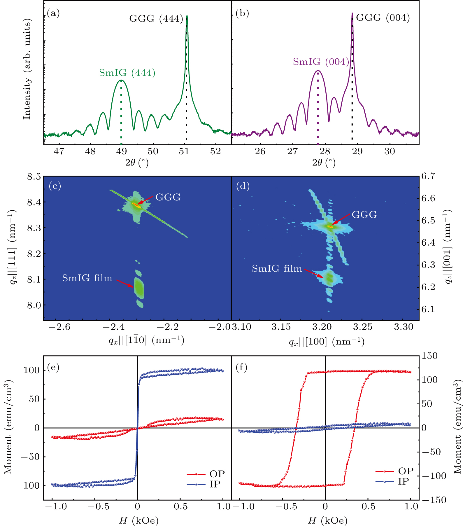
Fig. 1. [(a), (b)] High-resolution XRD θ–2θ scans of SmIG thin films deposited on GGG (111) and GGG (001). [(c), (d)] RSM performed around the GGG (486) and GGG (408) reflection of SmIG/GGG thin films. [(e), (f)] M–H hysteresis loops of SmIG/GGG (111) and SmIG/GGG (001) films in the IP and OP directions.
Download figure:
Standard imageIn order to explore the effect of crystal orientation on the spin state, the films' magnetization was measured at room temperature with an external magnetic field along either IP or OP direction. Figures 1(e) and 1(f) present the typical hysteresis loops for SmIG/GGG (111) and SmIG/GGG (001) films, respectively, with the paramagnetic contribution subtracted from the whole magnetization. It is found that the SmIG/GGG (111) film shows in-plane easy-axis, in which the spins prefer to align in the film plane. For IP measurement geometry, the saturated magnetization (MS) is ∼ 99.4 emu/cm3, and the coercive field (HC) is 3.4 Oe (1 Oe = 79.5775 A⋅m−1). When the film crystal orientation changes to (001) direction, it is interesting to find that the SmIG film shows a typical PMA behavior, in which the magnetic moments preferentially point perpendicular to the film plane. Moreover, both the MS and HC, obtained with OP measurement geometry, are enhanced up to ∼ 118 emu/cm3 and ∼ 345 Oe, respectively. In order to check this, the SmIG films were also fabricated on the GSGG (111) and (001) substrates (see Fig. S1 in supplementary material). Similar results are found that SmIG/GSGG (111) has in-plane anisotropy, and SmI G/GSGG (001) film prefers to show PMA. The magnetostriction coefficient of SmIG has a large negative value in the [111] direction and a large positive value in the [001] direction. With the compressive stress, the epitaxial SmIG/GGG (111) film would prefer to possess magnetoelastic anisotropy same as the shape anisotropy, and then its easy magnetization axis is along in-plane. While, the magnetoelastic anisotropy of the SmIG/GGG (001) film could overcome the shape anisotropy, and thus produce a perpendicular easy magnetization axis. These observations are different from the previous theoretic prediction in which SmIG/GGG (111) film holds PMA.[43] To better express the magnetic anisotropy, an anisotropy ratio (K = MOP/MIP) is defined and calculated, in which MOP and MIP are out-of-plane and in-plane magnetization obtained with magnetic field ∼ 1 kOe. It is found that the K values are 0.09 and 6.56 for SmIG films on GGG (111) and GGG (001), respectively. These observations shown above confirm not only that PMA is easily obtained on (001)-oriented substrate but also that the crystal orientation shifting is an effective method for the magnetic anisotropy switching in garnet films.
As mentioned above, materials with PMA are desirable for spintronic devices because they allow higher memory density.[4–6] Garnet films with different thicknesses are needed for diverse spintronic devices. We also grew epitaxial SmIG thin films with thicknesses t ranging from 8.8 nm to 85.5 nm on GSGG (001) substrates. Figure 2(a) shows θ–2θ XRD scans of the SmIG films of four different thicknesses. The pronounced Laue oscillations are observed in all films indicating smooth surfaces and sharp SmIG/GSGG interfaces. The OP lattice constants dOP of the SmIG films are calculated according to the prominent peak position (black arrows in Fig. 2(a)), and they are listed in Table 1. It is found that the dOP is ∼ 12.708 Å for 8.8-nm film, while other SmIG films have the same lattice constants (∼ 12.678 Å). With exploring the magnetization of obtained SmIG films, surprisingly, all SmIG/GSGG (001) films with different t show strong PMA, which can be obtained by combining Figs. 2(b) and 2(c). In addition to that, several points of magnetic properties of the SmIG/GSGG (001) films are worthy of attention. First, the saturation magnetization per unit volume of all films remains substantially unchanged (∼ 128 emu/cm3) except for the 8.8-nm film (∼ 110 emu/cm3) in the OP direction. Second, the magnetic field required for saturation magnetization gradually increases with the increasing t, which even reaches 445 Oe for t = 85.5 nm. Moreover, the shape of the M–H hysteresis loop also changes significantly as t increases, which may correlate to the evolution of the magnetic domain. Third, the anisotropy ratio (K) increases firstly to the maximum at 24.0 nm and decreases rapidly and then gradually increases with t increases, as shown in the Table 1.
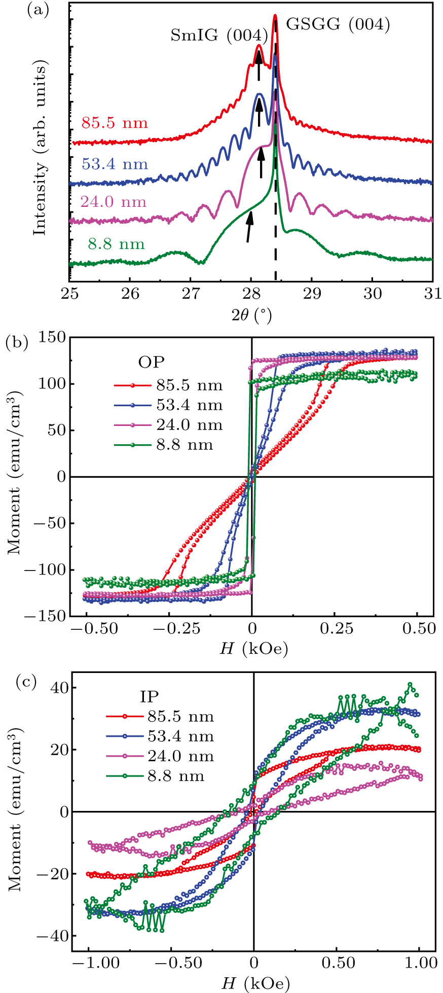
Fig. 2. (a) High-resolution XRD θ–2θ scans of SmIG thin films grown on GSGG (001) with different thickness (t). [(b), (c)] M–H hysteresis loops of SmIG/GSGG (001) films in the OP and IP directions.
Download figure:
Standard imageTable 1. The OP lattice constant dOP of SmIG/GSGG (001) film was acquired from XRD data. The magnetization of OP (MOP) and magnetization of IP (MIP) of SmIG thin films obtained from M–H measurements at 300 K. The anisotropy ratio (K) of SmIG thin films was calculated.
| t (nm) | dOP (Å) | MOP (emu/cm3) | MIP (emu/cm3) | K |
|---|---|---|---|---|
| 8.8 | 12.708 | 110.88 | 31.40 | 3.531 |
| 24.0 | 12.678 | 128.69 | 14.83 | 8.678 |
| 53.4 | 12.678 | 134.85 | 30.98 | 4.353 |
| 85.5 | 12.678 | 128.14 | 19.57 | 6.547 |
In addition to spin manipulation in a single magnetic film, the study of spin coupling in magnetic heterojunction systems has also drawn significant attention in the past few decades.[44–46] Except exchange bias interaction existing in ferromagnetic/antiferromagnetic heterojunctions,[47,48] another remarkable example is the combination of ferromagnetic metal (FMM) and ferromagnetic insulating (FMI) garnets, which simultaneously allows low-damping propagation of short-wavelength spin waves and electrical generation/manipulation/detection of spin waves.[22,49–51] In this context, spin manipulation in the FMM/SmIG heterojunctions, especially optical pumping induced spin wave modulation,[52–54] is also of major interest in this field. Here, we constructed CoFe/SmIG magnetic heterojunctions and conducted a study on the spin wave modulation by tuning the magnetic anisotropy of SmIG film. As schematically shown in Fig. 3(a), 10-nm ferromagnetic CoFe thin film with in-plane anisotropy was grown on SmIG/GGG (111) film by magnetron sputtering.[55] To prevent oxidation, an aluminum (Al) capping layer (∼ 5 nm) was grown on the samples' surfaces. The spin dynamic behavior of different samples was studied by a typical TR-MOKE technique.[56]
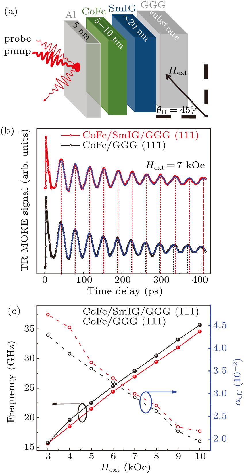
Fig. 3. (a) Illustration of the sample layer structure and experimental geometry for TR-MOKE measurements. (b) TR-MOKE signals measured under Hext = 7 kOe of CoFe/GGG (111) and CoFe/SmIG/GGG (111) heterostructures. (c) Corresponding precession frequency and effective magnetic damping factor as a function of Hext.
Download figure:
Standard imageFigure 3(b) shows the typical TR-MOKE curves for CoFe/SmIG/GGG (111) and CoFe/GGG (111) samples measured at 300 K under an external magnetic field Hext = 7 kOe. Both curves exhibit an obvious precession and damping relaxation behaviors. The TR-MOKE signals of both samples are derived from the magnetic moment precession of CoFe layer. However, when the time-domain spectral signals of the two samples are carefully compared, it can be found that the two samples with the same Hext have different precession periods, as shown by vertical dashed lines in Fig. 3(b). That means the spin dynamic behavior of CoFe/SmIG heterojunction is different from CoFe single layer, which indicates that there exists interfacial spin coupling between SmIG and CoFe layers. To quantitatively describe the spin dynamic difference between a single FMM layer and FMM/FMI heterojunction, the experimental results, shown in Fig. 3(b), are fitted by the following formula:[46]

where a corresponds to the background signal, b and t0 are related to the slow magnetization recovery process. The parameters c, f, φ, and τ refer to the oscillation amplitude, precession frequency, initial phase, and lifetime of the magnetization precession dynamics in the third term. According to the Fourier transform (FFT) results for Hext = 7 kOe, the precession frequency is reduced from 27.92 GHz to 26.96 GHz with the addition of SmIG film. Moreover, the effective magnetic damping factor (αeff) can be calculated as 0.029 and 0.030 for CoFe single layer and CoFe/SmIG heterojunction respectively, according to the simple approximate equation of αeff = 1/(2πfτ).[57]
Similar TR-MOKE measurements were done with the different external magnetic field, and the field dependence of f and αeff are summarized in Fig. 3(c). It is found that the f increases and αeff decreases monotonically with the increase of magnetic field, which is consistent with previous works.[56,58] Moreover, the reduction of the f and enhancement of αeff, induced by adding SmIG with CoFe, can be found in the whole measurement magnetic field range. These results indicate once again that there is the exact spin coupling between SmIG and CoFe layers, and the CoFe/SmIG heterojunction possesses a lower precession frequency and higher effective magnetic damping factor comparing with a single CoFe layer.
In the FMM/garnet heterojunctions studied here, the CoFe magnetic metal can be used to generate, manipulate, and detect the spin waves, and the SmIG film with low-loss property enables long-distance, coherent spin-wave propagation.[49] Such hybrid ferromagnetic heterojunction would allow low-damping propagation and electrical generation/manipulation/detection of high frequency spin waves simultaneously, which is quite useful in spintronic devices. Accordingly, the interlayer coupling and its manipulation in CoFe/SmIG are crucial for the application of such a hybrid ferromagnetic heterojunction. In this context, we fabricated two kinds of FMM/garnet heterojunctions, i.e., CoFe/SmIG (111) and CoFe/SmIG (001), to study the magnetic anisotropy switching effects. Keeping CoFe (∼ 5 nm) with in-plane easy-axis fixed, the SmIG layer's magnetic anisotropy was modulated by changing the orientation (Fig. 1). And then, the CoFe/SmIG (111) and CoFe/SmIG (001) heterojunctions would have different spin structures due to the interlayer coupling as schematically shown in Figs. 4(a) and 4(b). The anisotropy field H k_CoFe/SmIG of heterojunctions can be expressed as H k_CoFe/SmIG = H k_CoFe + H coupling_ CoFe/SmIG, where H coupling_CoFe/SmIG is the coupling equivalent field between SmIG and CoFe due to the interfacial spin coupling. For CoFe/SmIG (111), the spin vector in both CoFe and SmIG are preferred to align in-plane, and then the H k_CoFe/SmIG (111) is parallel to the sample surface along the Y axis as shown in Fig. 4(a). As for CoFe/SmIG (001), due to the switching of the easy-axis of the SmIG layer, the direction of H k_CoFe/SmIG (001) would tilt some angle away from the Y axis as shown in Fig. 4(b). Such tilting would lead to different effective magnetic field H eff, in both the magnitude and direction, of the heterostructures because of H eff = Hk + H ext. For the similar magnitude of H k_CoFe/SmIG (111) and H k_CoFe/SmIG (001), it is expected that H eff_CoFe/SmIG (001) is larger than H eff_CoFe/SmIG (111) due to the titling of H k_CoFe/SmIG (001), as shown in Fig. 4(b). It is known that the precession frequency is proportional to the H eff as f∼γ H eff, where γ is the gyromagnetic ratio. Accordingly, a higher precession frequency of CoFe/SmIG (001) heterostructure is expected.
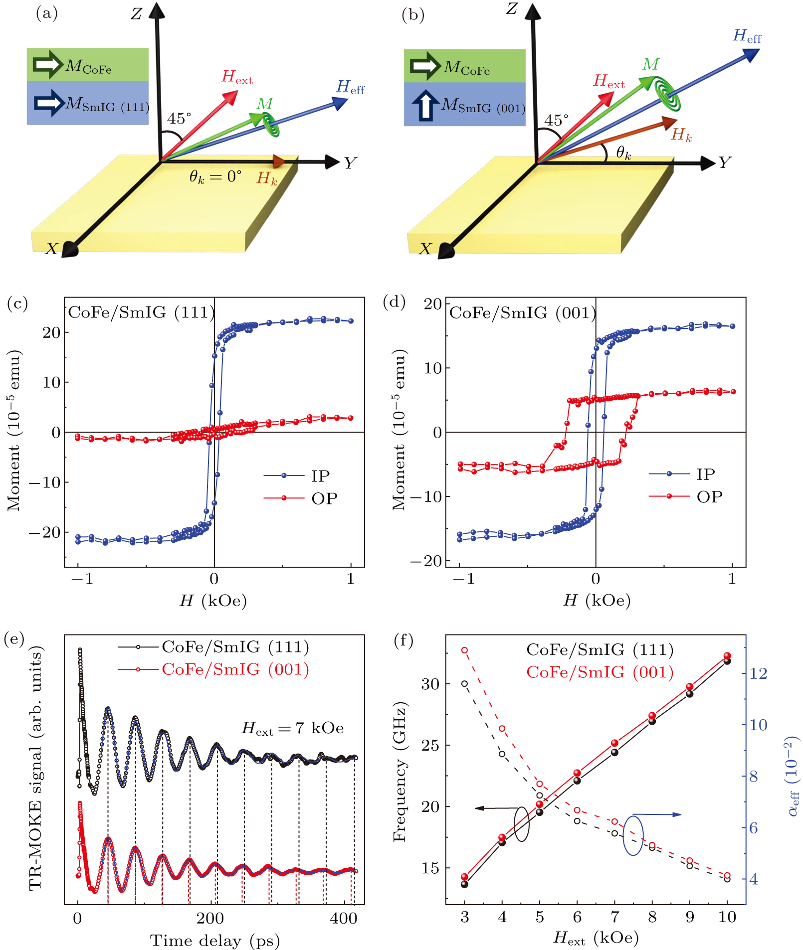
Fig. 4. [(a), (b)] Schematic diagram of the coordinate system for TR-MOKE measurement of the CoFe/SmIG (111) and CoFe/SmIG (001) heterostructures. [(c), (d)] M–H hysteresis loops of the two heterostructures. (e) TR-MOKE signals measured under Hext = 7 kOe for two heterostructures. (f) Dependences of precession frequency and effective magnetic damping factor αeff on Hext.
Download figure:
Standard imageFigures 4(c) and 4(d) show M–H hysteresis loops for CoFe/SmIG (111) and CoFe/SmIG (001) heterostructures, respectively. The CoFe layer's magnetization is comparably stronger than of the SmIG layer, and the CoFe/SmIG heterojunction show in-plane anisotropy. However, by switching the SmIG layer's easy-axis, the magnetic anisotropy of the whole CoFe/SmIG heterojunction structure is still manipulated. For the IP magnetization measurement, the MS and HC are slightly different between CoFe/SmIG (001) and CoFe/SmIG (111) heterostructures. For OP measurements, however, the orientation induced differences are much apparent. In detail, the MS is ∼ 6.5 × 10⁻⁵ emu for CoFe/SmIG (001) heterostructure, while it is only ∼ 3.0 × 10⁻⁵ emu for CoFe/SmIG (111) heterostructure. Moreover, by changing crystal orientation from (111) to (001), the HC is enhanced from 165 Oe to 220 Oe dramatically.
In addition to the effect on static magnetization, the magnetic anisotropy switching effect on CoFe/SmIG heterojunction's spin dynamics has also been studied. Figure 4(e) presents the TR-MOKE spectra under 7 kOe for CoFe/SmIG (001) and CoFe/SmIG (111) heterostructures. It is interesting that the two samples have different precession periods, as shown by vertical dashed lines in Fig. 4(e), similar to the results shown in Fig. 3(b). This indicates that the magnetic anisotropy switching can affect not only static but also dynamic spin behaviors in CoFe/SmIG heterojunctions. By fitting these dynamic Kerr signals using Eq. (1) and doing FFT, the precession frequency and effective magnetic damping factor are obtained as shown in Fig. 4(f). It is found that with switching crystal orientation from (111) to (001), both the precession frequency f and αeff of CoFe/SmIG heterojunctions are enhanced. Such enhancement (fCoFe/SmIG (001) > fCoFe/SmIG (111)) can be found in the whole measurement Hext range and are more evident in lower field cases. This feature confirms interlayer exchange coupling and the above expectation that the H eff_CoFe/SmIG (001) is larger than H eff_CoFe/SmIG (111) due to the titling of H k_CoFe/SmIG (001) (Figs. 4(a) and 4(b)).
4. Conclusion
In summary, magnetic anisotropy switching in SmIG films and its effect on spin dynamics of CoFe/SmIG heterojunctions have been studied. By changing substrate orientation from (111) to (001) direction, the magnetic anisotropy of SmIG films switches from in-plane to out-of-plane. Similar results can be found for the films on GSGG substrates. More importantly, by utilizing the TR-MOKE technique, the magnetic anisotropy switching effects on the spin wave in CoFe/SmIG magnetic heterojunctions were observed. Both the frequency and effective damping factor of spin precession in CoFe/SmIG heterojunctions can be modulated by the magnetic anisotropy switching of SmIG films.
See the Supplementary material for more details of XRD and M–H results for SmIG/GSGG (111) and SmIG/GSGG (001) films.
Acknowledgments
We thank Ms. Jingjing Gao and Prof. Can Xie for fruitful discussions. A portion of this work was performed on the Steady High Magnetic Field Facilities, High Magnetic Field Laboratory, CAS and supported by the High Magnetic Field Laboratory of Anhui Province.
Footnotes
- *
Project supported by the National Key Research and Development Program of China (Grant Nos. 2017YFA0303603 and 2016YFA0401803), the National Natural Science Foundation of China (Grant Nos. U2032218, 11574316, 11874120, 61805256, and 11904367), the Plan for Major Provincial Science & Technology Project (Grant No. 202003a05020018), and the Key Research Program of Frontier Sciences, CAS (Grant No. QYZDB-SSW-SLH011).