
Abstract
A highly flexible and continuous fibrous thermoelectric (TE) module with high-performance has been fabricated based on an ultra-long single-walled carbon nanotube fiber, which effectively avoids the drawbacks of traditional inorganic TE based modules. The maximum output power density of a 1-cm long fibrous TE module with 8 p–n pairs can reach to 3436 μW ⋅ cm−2, the power per unit weight to 2034 μW ⋅ g−1, at a steady-state temperature difference of 50 K. The continuous fibrous TE module is used to detect temperature change of a single point, which exhibits a good responsiveness and excellent stability. Because of its adjustability in length, the flexible fibrous TE module can satisfy the transformation of the temperature difference between two distant heat sources into electrical energy. Based on the signal of the as-fabricated TE module, a multi-region recognizer has been designed and demonstrated. The highly flexible and continuous fibrous TE module with excellent performance shows a great potential in diversified applications of TE generation, temperature detection, and position identification.
Export citation and abstract BibTeX RIS
1. Introduction
Thermoelectric (TE) modules can directly convert various of thermal energy generated from nature or industrial production activities into valuable electric energy, which have attracted extensive attention because of their potential application in the next generation power generator.[1] Traditional inorganic TE materials have been widely studied, but due to the presence of toxic heavy metals and other defects, their flexibility is poor, which seriously hindered their future application.[2,3]
The development of environment-friendly, non-toxic, flexible, and lightweight TE modules has become an important branch of TE research. Organic polymers,[4–6] carbon materials,[7–12] and their hybrid materials[13–27] are possible alternatives to traditional TE materials. Markedly, carbon nanotube (CNT) has great potential for use in the flexible TE materials because of its nontoxic, abundant source-materials, high electrical conductivity (σ), controllable Seebeck coefficient (S), and the high specific energy enabled by their light weight.[26,27] So, there are many researches emerging rapidly on CNT-based TE materials and modules, to meet these new requirement for sustainable energy devices. Nevertheless, how to improve their performance (e.g., power factor larger than 1000 μW ⋅ m−1 ⋅ K−2, specific energy higher than 1000 μW ⋅ g−1, etc.) is still far difficult. Here, power factor (PF = S2 σ) is related to the usable power attainable from the TE materials. It is found that a pristine single-walled carbon nanotube (SWCNT) film presents p-type behavior.[28,29] Our p-type as-grown SWCNT thin film got a PF of 2482 μW ⋅ m−1 ⋅ K−2,[10] which can be rapidly and conveniently switched to the n-type film (with σ 1500 μW ⋅ m−1 ⋅ K−2 at room temperature) directly by drop-casting the solution of polyethyleneimine (PEI) in ethanol.[18] Recently, a carbon-based p-type composite film reached a PF of 2710 μW ⋅ m−1 ⋅ K−2.[19] In addition, n-type film based on the SWCNT films functionalized with benzyl viologen resulted in a maximum PF of 3103 μW ⋅ m−1 ⋅ K−2. A TE module exhibited a power density of 1180 μW ⋅ cm−2 at Δ T = 20 K.[20] Up till now, several groups have reported the fibrous TE modules based on CNTs. Choi et al. prepared a TE module based on CNT yarn which is alternatively doped into n- and p-type by PEI and FeCl3. The TE module with 60 p–n pairs shows maximum power density of 697 μW ⋅ g−1 at Δ T = 40 K.[21] Using aligned wet-spun CNT fibers, Park et al. fabricated a flexible TE generator with 40 p–n pairs, which shows the maximum power output of 1900 μW ⋅ g−1 at a temperature gradient of 30 K.[22] However, there are a lot of problems for further investigation, e.g., impact of the size of fibrous CNTs,[23,24] low specific energy, etc.[27] Therefore, it is a great challenge to improve the practical performance of flexible fibrous TE modules.
Hereby, we report a highly flexible and continuous fibrous TE module with high performance fabricated from an ultra-long SWCNT fiber for energy harvesting and explore its potential applications, thus effectively avoiding the drawbacks of traditional inorganic TE-based modules. The pristine SWCNT fibers exhibit great p-type TE property without further doping, which can rapidly switch to n-type ones by drop-casting the solution of PEI in ethanol, just like we have done before with p-type SWCNT films.[10] Unlike the CNT film-based TE module, the p–n nodes of a fibrous TE module adopt point connection mode, which can make full use of the heat source. The continuous fibrous TE module is used to detect the temperature change of a single point, with good responsiveness and excellent stability. The effect of length of the TE module on the output power performance has been investigated. Thanks to its adjustability in length, the fibrous TE module can satisfy the transformation of the temperature difference between two distant heat sources into electrical energy. Moreover, to present its diversified application, a self-powered temperature detector and multi-region recognizer, based on the as-obtained fibrous TE module, are assembled and demonstrated.
2. Experimental section
2.1. Preparation of the SWCNT-based TE fiber
The p-type SWCNT fibers: The p-type SWCNT fiber was directly and continuously synthesized by a BACVD method.[30,31] Typically, methane (about 20 sccm) was used as carbon source, argon gas as carrier gas, ferrocene as catalyst, and sulfur as promoter. The temperature of the reaction region was controlled at σ 1100 °C. Then, the p-type SWCNT fiber was obtained continuously by condensing the film via a liquid, as described in our previous work.[30,31]
The n-type SWCNT fibers: The PEI solution with a certain concentration of PEI in ethanol was dropped onto the pristine SWCNT fiber. Then, the hybrid fiber was dried in air for 10 min for further performance testing.
2.2. Preparation of fibrous TE module
First, a pristine SWCNT fiber was uniformly wound on a PET substrate with a certain width. A scotch tape covered one side of the pristine fiber, to ensure that the raw p-type SWCNT fibers on this side were not contaminated by PEI. Then, the SWCNT fibers on the other side were dropped with 2-wt% PEI solution. Finally, the p–n modules were dried in air for 10 min.
2.3. Characterization and measurements
Microscopic morphologies were examined using a Hitachi S5200 SEM system operated at 1 kV. The electrical conductivity and Seebeck coefficient in this study were measured in air at room temperature using the four-electrode method.[10] The resistance and output voltage were measured using a Keithley 2400 multimeter. The TE performance of the as-prepared module fixed on the testing appratus at the various steady-state temperature gradient were tested by a Keithley 4200-SCS. The temperature is measured using a T-type thermocouple.
3. Results and discussion
3.1. The property of TE fiber
The pristine SWCNT fibers are directly and continuously synthesized.[30,31] The fiber has a good electrical conductivity of about 2.6 × 10⁵ S ⋅ m−1 without any further processing. Its Seebeck coefficient retains about 76 μV ⋅ K−1 at room temperature. As a result, the maximum PF of p-type fiber 1486 μW ⋅ m−1 ⋅ K−2 has been obtained. For the n-type hybrid fibers, we choose the PEI solution which has been studied to increase the electron concentration and shift the Fermi level of SWCNT towards conduction band.[14,18] During doped with PEI solution, the loose spaces of a pristine fiber (see in Fig. 1(a)) ensures the penetration of the PEI solution. When the solution is infiltrated, the diameter of the fiber decreases, from about 65 μm to 30 μm, as shown in Figs. 1(a) and 1(b), respectively.
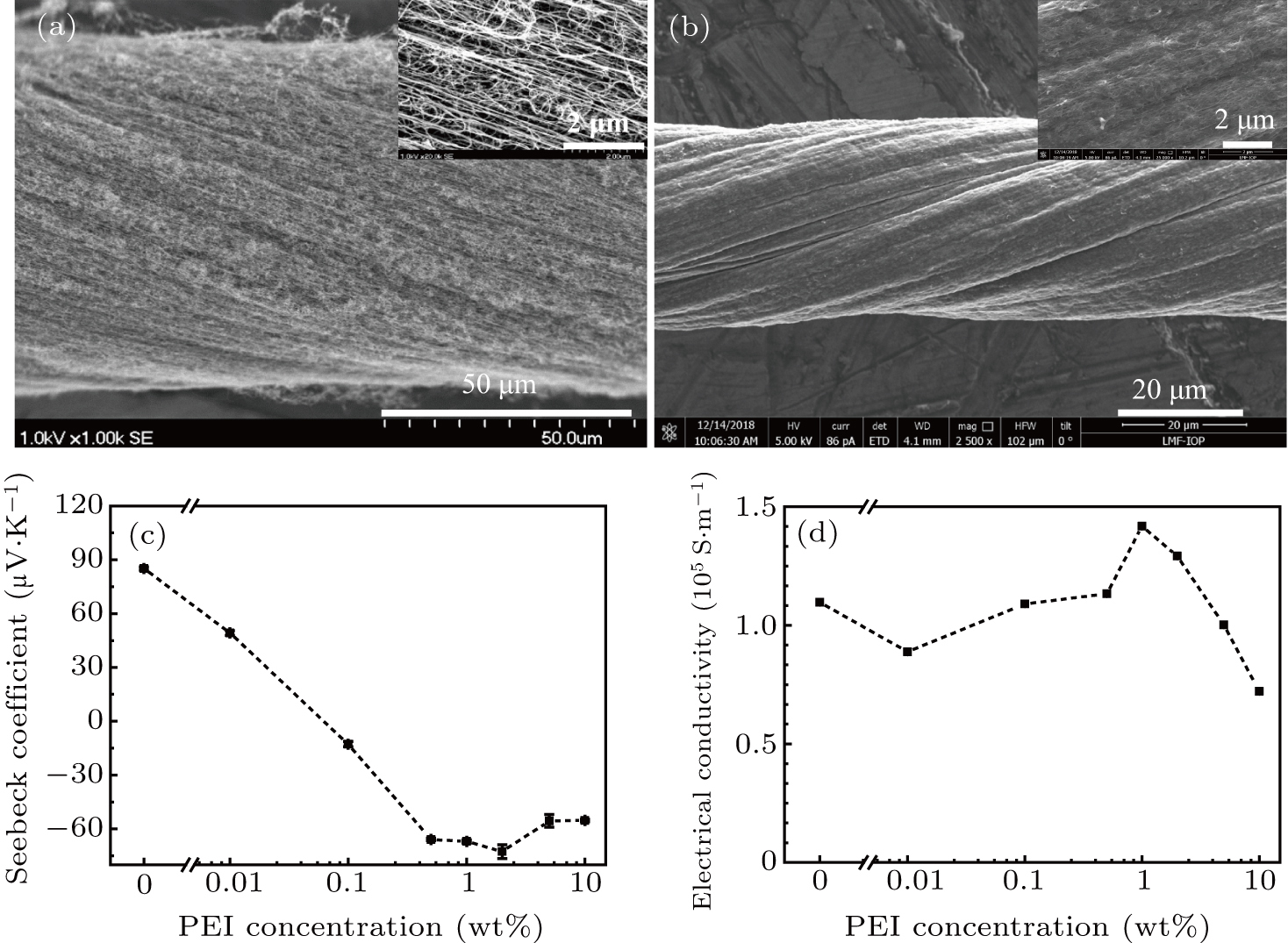
Fig. 1. (a) SEM images of the pristine SWCNT fiber. (b) The SWCNT-PEI hybrid fiber treated with 2-wt% PEI solution. The insets in panels (a) and (b) are the corresponding high resolution SEM images. (c) Seebeck coefficient and (d) electrical conductivity of SWCNT-PEI composites with varying concentrations of PEI ethanol solution ranging from 0.01 wt% to 10 wt%.
Download figure:
Standard imageWe explored the effect of doping concentration of the PEI solution (as shown in Figs. 1(c) and 1(d)). As the concentration of the PEI solution increases to 2 wt%, the Seebeck coefficient of the n-type composite reaches to –72.4 μV ⋅ K−1, the electrical conductivity is 1.29 × 10⁵ S ⋅ m−1, the maximum PF of the SWCNT-PEI composites is 682.5 μW ⋅ m−1 ⋅ K−2 (as shown in Fig. 1(d)). Then, many batches of SWCNT fibers were doped with 2-wt% PEI. The PF of composites can reach to 1160 μW ⋅ m−1 ⋅ K−2.
3.2. The property of TE module
Modules mode of p-type and n-type SWCNT fibers are fabricated without any electrically connecting, as shown in Fig. 2(a). The preparation details are shown in the experimental section. A pristine SWCNT fiber is uniformly wound around a PET substrate with 5 kinds of widths (1 cm, 2 cm, 3 cm, 4 cm, and 5 cm). A scotch tape covered one side of the SWCNT fibers to ensure that the raw SWCNT p-type fibers are not contaminated by PEI. Then the fibers on the other side of PET were doped with 2-wt% PEI solution. In this case, the connection of each pair of p- and n-type fibers is the point connecting. Because of no other metal connections, the internal resistance of modules caused by connection was eliminated.
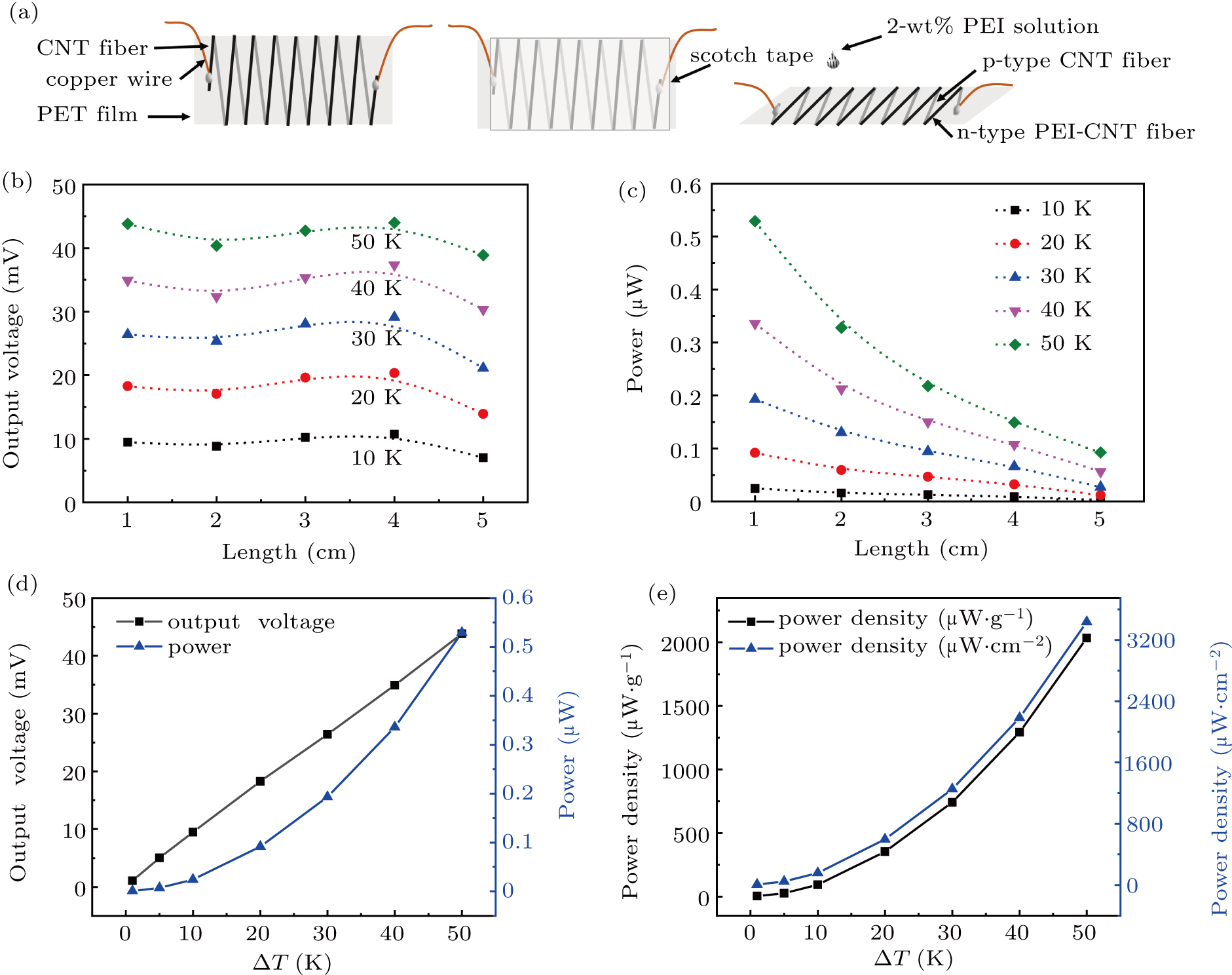
Fig. 2. (a) The assembling process of fibrous TE module. (b) The voltage and (c) the maximum output power of five TE modules, with different lengths and 8 pairs of p–n couples, changed with temperature differences. (d) The output voltage and the maximum output power of the 1-cm long TE module with 8 pairs of p–n couples changed with various temperature differences. (e) The maximum output power of unit mass and unit area of the 1-cm long TE module with 8 pairs of p–n couples at a series of temperature differences.
Download figure:
Standard imageWe measured the open circuit voltages (Voutput) of five modules under different temperature differences, as shown in Fig. 2(b). Under the same temperature difference (Δ T), the open circuit voltages of the modules with different lengths are basically similar, which indicates the uniformity of doping. According to the formula


where Sn, Sp are the Seebeck coefficients of the n-type and p-type fibers, respectively. nn, np are the numbers of n-type and p-type fibers contained in the modules. We can achieve Sn + Sp ≈ 111.5 μV ⋅ K−1 for the average of five modules. It shows that the modules are adjustability in length without affecting the Seebeck coefficient of one p–n couple in the TE modules.
Next, the maximum output power of the five TE modules with eight pairs of p–n couples changing with temperature difference is shown in Fig. 2(c). When Δ T = 50 K, the maximum output power of 1-cm long with 8 pairs of TE module is the largest. The maximum power output (Pmax) can be calculated according to

Rin is the internal resistance of the module.[24] When the load is the same as the internal resistance, the output power of the module reaches the maximum. For the same pairs, at the same temperature difference, the output open circuit voltage is similar. With the increase of the length, the internal resistance of the module increases, which leads to the maximum output power of the module decreases. As a result, the 1-cm long with 8 pairs of TE module has achieved the largest maximum output power.
Furthermore, we explore the power density of a module with 1 cm in length and 8 pairs of p–n couples in detail, as shown in Figs. 2(d) and 2(e). The open-circuit voltage 43.82 mV and short-circuit current 0.048 mA have achieved while the modules at a steady-state temperature difference 50 K at ambition environment. The maximum output power is 0.529 μW. By measuring the masses of the pristine fibers and doped fibers, the average line density of p-type pristine fiber is about 0.016 mg ⋅ cm−1, the average line density of n-type composite fiber is about 0.021 mg ⋅ cm−1. So the maximum output power density is 3436 μW ⋅ cm−2, the power per unit weight is about 2034 μW ⋅ g−1 at Δ T = 50 K. The average output power of a pair of p–n couples with 1 cm and 1 K is 8.59 μW ⋅ cm−2, 5.09 μW ⋅ g−1. This power density is substantially higher than the previously reported power density for fibrous TE modules, which is 1900 μW ⋅ g−1 at Δ T = 30 K with 40 p–n couples.[22]
3.3. The application of TE module
3.3.1. Temperature detection
Based on the Seebeck effect, a temperature difference detector made by the module is prepared. We test the temperature response of the three kinds of temperature detectors including 8 pairs of couples with 1 cm, 2 cm, and 5 cm as shown in Fig. 3. We put one end of the detectors at a constant temperature, increase the temperature of the other end, and a temperature change is produced. There is a good linear relationship between the output voltage and the temperature change. The output voltage could effectively reflect the temperature change of a single point. So the change trend of the output voltage produced by detectors and the temperature change measured by the T-type standard thermocouple is consistent.

Fig. 3. The response and recovery of the three kinds of TE modules with 8 pairs of couples when a temperature difference happened between the two ends of a module. Δ T is detected by a T-type standard thermocouple, while the output voltage is produced by the module: (a) 1-cm long module, (b) 2-cm long module, (c) magnified image of the rectangular region in (b) with red dots. The red line shows the fitting curve of the recovery time constant of the module, (d) 5-cm long module.
Download figure:
Standard imageThen the response and recovery of the detector are analyzed. The detector has a fast response when a temperature change appears. We calculate that the average response time of the detector is about 0.25 s at Δ T = 0.3 K – 1 K. The temperature detector realizes fast single point test and repeatability test. And during the repeated test, the response of the detector remains stable.
To estimate the recovery time constant of the detector, we consider decay of the temperature under the time (t)-dependent heat diffusion theory. According to the heat dissipation process of the detector, we obtain the variation process of the voltage, V(t), of the detector with time

where V0 is the output voltage of the detector in the steady state, Vmax is the maximum output voltage of the detector. We fit the recovery curve of the detector made of 2-cm TE module, and obtain the recovery time constant (τ) of the detector of about 4.45 s, as shown in Fig. 3(c).
By analyzing the data of the recovery processes in Fig. 3, we get that the average recovery time constant of the three detectors is about 4 s at Δ T = 0.3 K–1 K. For the TE modules with different lengths, their recovery time constant is all independent of its lengths. The results indicate that they all have good temperature detection capabilities.
3.3.2. Thermoelectric generation
Figure 4 demonstrates that the as-fabricated flexible TE modules can generate electrical energy from the heat resource found easily in daily life. Fibrous type TE modules were assembled by different lengths to meet their scalability. A flexible TE module made of longer fibers was used to contact two separate heat sources like a curved bridge. As shown in Fig. 4(a), a 5-cm long flexible TE fibrous module with 8 pairs of p–n couples could take its advantage to determine the output voltages generated by the temperature difference between two beakers. The voltage reached to about 19.5 mV at Δ T = 36.1 K. By further increasing the length, the fibrous TE module can transform the temperature difference between two distant heat sources into electrical energy. The increase of the length is also conducive to the utilization of the heat source with a certain depth.
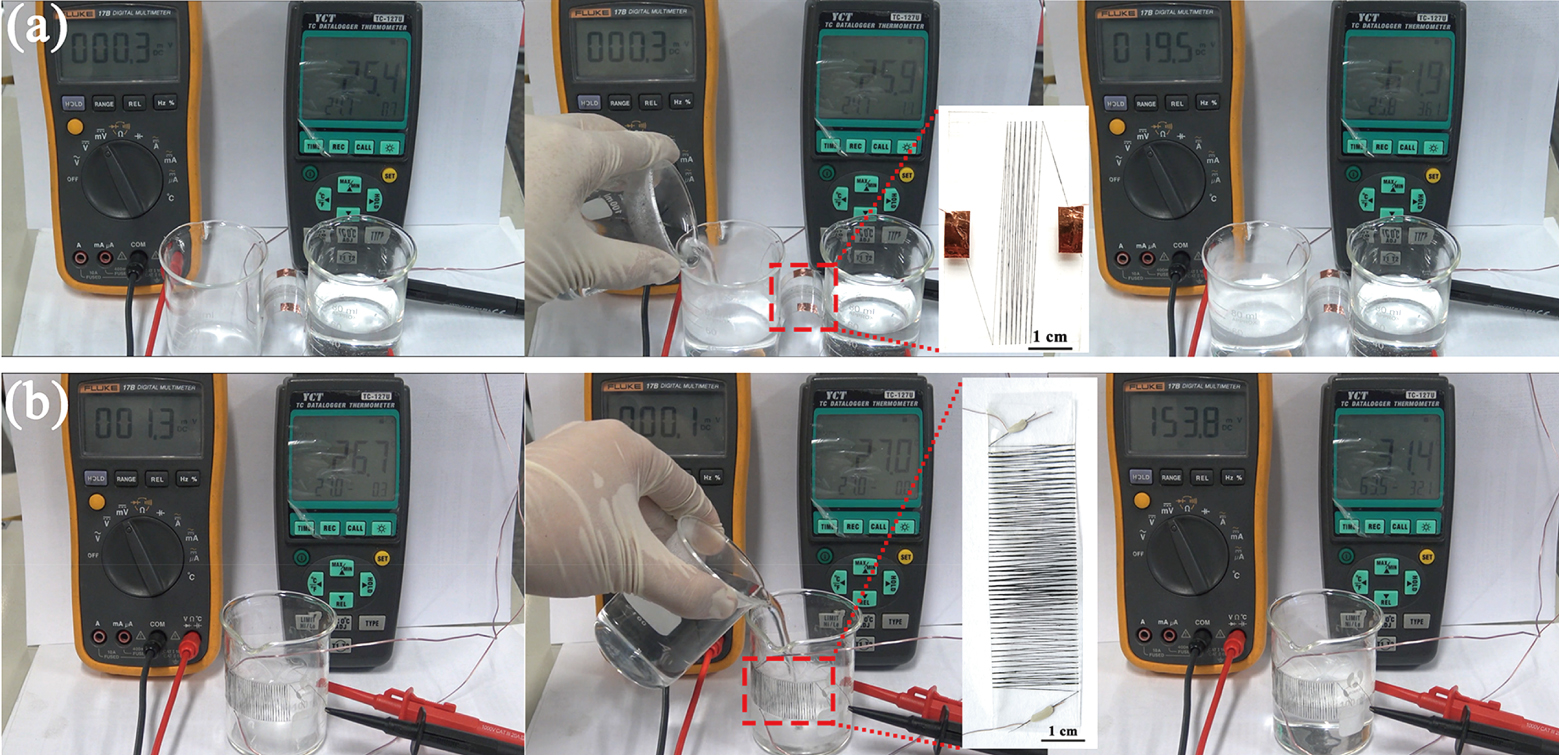
Fig. 4. The use in daily life of flexible fibrous TE modules during the process of converting heat energy into electrical energy. (a) The response of a module, with 5-cm length and 8 pairs of p–n couples, to two separate heat sources. The output voltage reached to about 19.5 mV at Δ T = 36.1 K. (b) The response of a module with 2-cm length and 50 p–n pairs. The output voltage reached to about 153.8 mV at Δ T = 32 K.
Download figure:
Standard imageContinuous preparation of CNT fibers meets the sufficient supply of raw materials to fabricate the as-designed TE modules. Hereby, using a pristine CNT fiber over 200-cm long wound on a PET substrate uniformly, a TE module contains 50 pairs of p–n couples was prepared. As shown in Fig. 4(b), the module can fit tightly to the outer wall of a beaker due to its good flexibility. When the hot water was poured into the beaker, the temperature difference between the ambient temperature and the hot water runs up to 32 K. At the same time, the voltage at both ends of the module rapidly reached to about 0.153 V. Moreover, this kind module with more p–n couples could also be suitable for utilization of large area heat sources.
3.3.3. Multi-region recognizer
On the basis of fibrous TE module, a multi-region recognizer was assembled. TE signals are used to realize the identification of different regions. Ding et al. designed a multi-pixel recognizer based on TE fibers.[17] Different from the multi-pixel recognizer, the complexity in output signals of our designed multiregion recognizer is significantly reduced. For example, when four positions need to be detected, the multi-pixel recognizer should use four output signal detectors to distinguish the positions, but our multiregion recognizer can distinguish directly the positions only by two output signal detectors. The multiregion recognizer is described in detail as follows.
The multi-region recognizer consists of module a and module b, as shown in Fig. 5(a). The modules a and b are prepared by separating the compact TE module shown in Fig. 2(a) into two parts. The two parts contain the same number of p–n pairs. Then we integrated the modules a and b into four regions to achieve the function of position recognition similar to four quadrants. In the recognizer, there is no difference between modules a and b, but the angle of placement. Figure 5(b) shows the photograph of four-region recognizer made by 2-cm long modules. The schematic diagram of test is shown in Fig. 5(c).
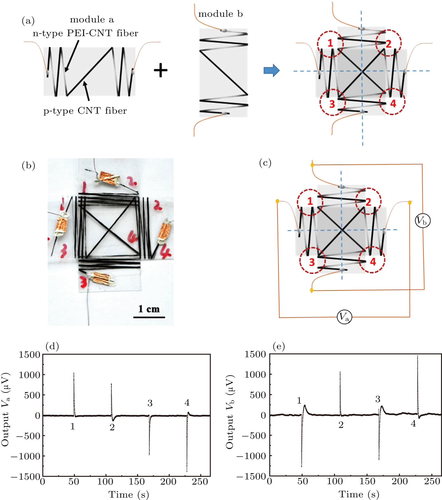
Fig. 5. (a) The assembling process of a four-region recognizer in which two TE modules are included. (b) The photograph of the recognizer. (c) The schematic diagram of test. (d) and (e) The response curves of modules a and b while four sections were touched by fingers in turn.
Download figure:
Standard imageWe put the four-region recognizer at room temperature, when one of the regions in the device is touched by a high temperature object (the temperature of the object is higher than the ambient temperature), two output voltages will be produced by the two voltmeters. According to the number and the symbol of the output voltages, the region touched by the object can be recognized. For example, when the voltmeter connected with the module a displays positive values, and the voltmeter connected with module b displays negative values, then we can recognize that the region touched by heat source is region "1". As a demonstration, we place the recognizer on a substrate at room temperature and touch four regions with our fingers. Figures 5(d) and 5(e) show the output voltage signals given by the modules a and b. The same numbers in the two figures represent two voltages generated at the same time. According to the output voltages, we can recognize that fingers touch region "1", region "2", region "3", and region "4" in turn.
The multi-region recognizer can also be placed in a corrosive environment as an alarm device. For example, when a temperature change caused by the corrosion heat is felt in a certain region of the device, the corroded position can be accurately identified according to the voltage signal generated by the multi-region recognizer.
4. Conclusions
In summary, a highly flexible and continuous fibrous TE module has been fabricated based on an ultra-long SWCNT fiber, with high performance, a high unit area power density and high unit mass power density. The maximum output power density of a 1-cm long fibrous TE module with 8 p–n pairs is 3436 μW ⋅ cm−2, the power per unit weight is 2034 μW ⋅ g−1, at Δ T = 50 K. Compared with conventional bulk or thin-film TE modules, fibrous TE modules can assemble more TE units per unit area in contact with heat sources. The length of the highly flexible fibrous TE module is variable to realize the utilization of the temperature difference between two distant heat sources. Meanwhile, the continuous fibrous TE module is used to realize single point temperature change detection, exhibiting its good responsiveness and excellent stability to temperature differences. Furthermore, based on the signal of the as-fabricated TE module, a multiple region recognition device was designed and demonstrated. The good performance of a highly flexible and continuous fibrous TE module ensures its great application prospect in the diversified fields of TE generation, temperature detection and position identification.
Footnotes
- *
Project supported by the National Key Research and Development Program of China (Grant No. 2018YFA0208402), the National Natural Science Foundation of China (Grant Nos. 11634014, 51172271, and 51372269), and the Strategic Priority Research Program of the Chinese Academy of Sciences (Grant No. XDA09040202).