

Abstract
We present a new global array of small aperture optical telescopes designed to study artificial satellites and the nearby universe: the Falcon Telescope Network (FTN). Developed by the Center for Space Situational Awareness Research in the Department of Physics at the United States Air Force Academy (USAFA), the FTN is composed of 12 observatories in the United States, Chile, Germany, and Australia, with a potential site in South Africa. The observatory sites were strategically selected with the main objective that once in operation, the telescopes will be capable of working together to perform simultaneous and/or continuous observations of a single object in the sky. This capability allows the observation of artificial satellites from different baselines in a wide range of orbits, continuous data acquisition of variable astronomical sources, and rapid response observations of transient phenomena that require almost immediate follow-up (gamma-ray bursts, novae, or supernovae, etc.). Consisting of commercially available equipment, each observatory is equipped with a 0.5 m primary mirror telescope, a CCD camera, photometric filters, including a special filter to detect exoplanets, and a diffraction grating. The FTN is designed for remote and robotic operation with a host of automation software and services housed on the site computers and at USAFA. FTN partners will have access to a web-based interface where both the observation application as well as the raw data obtained by any of the Falcon nodes will be available. The FTN is a collaborative effort between the USAFA and educational or research institutions on four continents, demonstrating that, through the cooperation of multiple institutions of different levels and capabilities, high-level scientific and educational programs can be carried out, regardless of the geographic location of the various network members.
Export citation and abstract BibTeX RIS
1. Introduction
1.1. Regarding the Study of Artificial Satellites from Ground Stations
A growing number of nations and commercial companies have developed the technology necessary to manufacture and launch their own orbital space systems. Although a few global powers have historically dominated this field, such as the United States, Russia, the European Community, China, India, Japan, and Canada, other countries are now becoming space-faring nations such as Mexico, Chile, Argentina, Taiwan, and Australia to name a few.
The fact that more and more countries have access to this type of technology has enabled significant advances in the field of communications, space research, and the study of the Earth. Nonetheless, this abrupt increase in the number of Earth-orbiting objects has also caused problems regarding managing and controlling the orbital population, resulting in collisions between satellites operating in low-altitude orbits. This scenario makes the development of new techniques to characterize artificial satellites a priority. These techniques would enable the development of tools to accurately determine both the number as well as the type of objects that are in various Earth orbits.
For several decades now, astronomy observation techniques have been applied in the precise characterization of artificial satellites located at different orbits. Early on, authors such as Tousey (1957) and Kissell & Tyson (1964) devoted themselves to studying the properties associated with the optical detection of satellites, such as visibility, photometric orbit determination, and the temperature that a satellite reaches as a result of radiation exchange with the environment. On the other hand, in the 1960s and 70s, researchers from the United States Air Force worked on characterizing satellites through the phenomenon of polarization (Stead 1967) and studying the visible reflectance spectra (Lambert 1971). At present, researchers from around the world have made a considerable effort to improve studies of space object properties through techniques that do not require high spatial resolution, known as non-resolving techniques (Payne et al. 2002, 2006; Schildknecht et al. 2005; Hall et al. 2007; Seitzer et al. 2007; Schildknecht et al. 2009; Tippets et al. 2015).
Thus, Seitzer et al. (2007) were able to characterize geostationary satellites using photometric observations obtained through the use of Morgan & Johnson system filters and also by using the Space Object Identification (SOI) in Living Color (SILC) technique, concluding that the different satellite structures (bus) possess distinctive photometric properties that can feasibly be classified. This was improved by Bédard et al. (2012), who, using more refined observational techniques, determined that although satellites with the same bus may have similar photometric characteristics, they can be differentiated by eliminating a possible cross-sectional characterization of satellites.
Along with photometric analysis, there have been breakthroughs based on spectroscopic studies of artificial satellites. One of the most used traditional techniques in spectral observations is "long-slit spectroscopy." This technique refers to the use of an elongated slit aperture located between the object signal and the diffraction grating, in order to select a bounded region of the incident light beam, which is then dispersed by a primary element in order to obtain the detail of its spectral signature. This type of spectral observation in artificial satellites has previously been carried out and reported; however, the instrumentation and the long-slit observation technique is complex, mainly due to the type of movement that these satellites involve. Lambert (1971), using a scanning spectrograph, was able to obtain reflectance spectra in satellites and to detect the existence of aluminum in their coverage. This is explained by the fact that these materials are developed with components that are capable of protecting existing instrumentation on the interior of the satellites from external elements, such as friction or large changes in the temperature, to which they are exposed. Likewise, Jorgensen et al. (2004) discovered a reddening effect of artificial space objects when compared to laboratory samples.
Thus, several studies have harnessed the spectroscopic observation technique in order to find unique characteristics in Earth orbit systems. However, traditional observation techniques require much work and are difficult to carry out regarding systematic observations, something that is essential for the characterization of artificial satellites. This is due to the fact that it is only possible to obtain spectroscopic properties of one object at a time, requiring large amounts of observation time to generate sufficient databases for characterization studies. These observations are also very risky, as precise positioning is necessary to place an object moving at high angular speeds across the sky, as is the case for low-altitude satellite observations, in a very small area on the observation equipment (slit aperture).
In 1970, Hoag and Schroeder introduced a new technique for spectroscopic observations: slitless spectroscopy. These authors showed that slitless observations have a number of advantages: first, the spatial observation coverage allows spectroscopic surveys of different objects simultaneously. Along with this, the object center does not need a high guidance accuracy, because the light coming from the object does not need to pass through a slit. Finally, its configuration is simple due to the use of simple diffraction gratings. Nonetheless, an important disadvantage to highlight is that the information obtained is of very low spectral resolution. Additionally, there is no kind of filtering in the observation of an object; therefore, the different spectral moments may be confused within a same observation. Recently, Tippets et al. (2015) and Dunsmore et al. (2016) showed results of using slitless spectroscopy on glinting communication GEO satellites providing direct evidence that the source of the satellite glints are the solar panels.
In addition to using photometric and spectroscopic techniques to characterize artificial satellites, carrying out simultaneous observations performed from different perspectives and lighting conditions to study satellites has been proposed (Hall et al. 2012). One of the most noteworthy studies in this regard is Fulcoly et al. (2012), who, using photometric modeling tools, were able to demonstrate the power of using simultaneous spatial photometry from multiple telescopes to determine the basic forms of a satellite.
These studies show that determining orbital element properties is fundamental for the development of technology in the short term, transforming this into one of the priority areas in relation to the study of extraterrestrial sciences.
1.2. Regarding Global Arrays of Telescopes
Since the construction of the first optical systems for the study of the universe, researchers have become devoted to improving and expanding various tools in order to answer some fundamental questions. Engineering wonders have had to be developed in order to answer questions as essential as how was the universe created? or what were the initial conditions that formed the space that surrounds us today? These technological innovations have allowed us to detect energy coming from astronomical sources located at immense distances.
In this context, one of the methods designed to answer these questions was optical and infrared telescopes of ever-increasing size. During the first half of the 20th century, telescopes such as the Victor Blanco of the Astronomical Observatory in Cerro Tololo (Chile), with a 4 m primary mirror, the Hale telescope of the Mount Palomar observatory in the United States, with its 5.1 m primary mirror, or the 6 m Large Altazimuth Telescope, belonging to the Special Astrophysical Observatory (Russia), dominated observational astronomy as the largest optical telescopes in the world. However, these were quickly overshadowed by a new generation of much larger telescopes in the late 20th and early 21st century (e.g., 10 m Keck Telescopes, USA; 8 m Very Large Telescope (VLT) and Gemini in Chile, 10 m Southern African Large Telescope, among others). This new generation of telescopes brought human knowledge of the universe to levels that were unthinkable only 50 years ago with the discovery of, for example, more than 3000 exoplanets, or galaxies located at such distances that at the time of issuing the detected signal, the universe was no more than 400 million years old.
However, our search to understand our environment does not end at this point. Further, development in engineering, computing, and design have allowed us to develop a new generation of giant or extremely large telescopes: the 26 m Giant Magellan Telescope, located in the Cerro Las Campanas Observatory in the north of Chile, the 39 m European Extremely Large Telescope (E-ELT) of the European Southern Observatories also built in the Atacama desert of Chile, and the Thirty Meter Telescope project developed by a consortium of institutions, but still in the process of designating a final location.
Despite enormous technical and human advances employed in the construction of these high-level research centers, many current advanced systems remain insufficient to successfully pursue lines of research that require systematic and continuous temporal studies. Studies to detect extrasolar planets using the technique of stellar variability involve making temporal observations over hours or even days (Charbonneau et al. 2000). Defining supernovae light curves requires taking data night after night for months (Filippenko 1997). Furthermore, observing the optical counterparts of Gamma-ray bursts (GRBs) requires rapid responses from the telescopes as the brightness of these transient astronomical phenomena can diminish below detection limits in a matter of hours (Gehrels et al. 2009).
To respond to these events, a series of laboratories have been developed that are devoted to time domain observations. They seek to continuously collect data in the greatest possible time range through the construction of global arrays of telescopes. Recently, a series of these facilities have been established, some larger and more developed than others. Among these, we can highlight the Las Cumbres Observatory Global Telescope Network (Brown et al. 2013), composed of a network of 42 telescopes of various sizes throughout the world, and the Skynet Robotic Telescope Network which consists of 11 telescopes located at 17 observatories around the world, such as the PROMPT telescopes (Reichart et al. 2005), with locations in the United States, Canada, Italy, Australia, and Chile (https://skynet.unc.edu/). We can also add the Bell Observatory/Crimean Astrophysical Observatory/Kitt Peak National Observatory (BCK) Network of optical telescopes (McGruder et al. 2015), the Master Global Robotic Network (Lipunov et al. 2010), the Cooperation through Education in Science and Astronomy Research Telescope Network (CESAR, Cuesta & Vaquerizo 2014), among others, to these telescope networks. Finally, there is the International Scientific Optical Network (ISON), which is composed of approximately 80 telescopes worldwide dedicated primarily to observations and studies of manmade satellites, space debris, GRB afterglows, and asteroids (Molotov et al. 2008).
1.3. The Present Work
In this paper, we present a new global network of small aperture telescopes, developed by the Center for Space Situational Awareness Research of the Department of Physics at the United States Air Force Academy (USAFA), and dedicated to identifying and characterizing artificial satellites and studying the near universe: the Falcon Telescope Network (FTN). This is a more up-to-date paper than the conference proceedings of Chun et al. (2014). Thus, we have structured our study as follows. In Section 2, we describe the telescope network, with particular emphasis on the instrumental characteristics. In Section 3, we describe each of the sites that make up the global network, including their geographical characteristics and the local institutions that manage each telescope. In Section 4, we explain the control system designed for the remote control of each of the nodes. In Section 5, we present the first scientific results obtained to date, based on the data obtained by the nodes of the FTN that are already operating. In Section 6, we present a summary of the education and community outreach programs that have been designed by the FTN team, to be implemented with each of the nodes.
2. The FTN
The USAFA, through its Department of Physics, began designing a global network of small aperture robotic telescopes in 2012, devoted to studying artificial satellites and to astronomical studies of the near universe. This project was named the FTN. Led by the Center for Space Situational Awareness Research (CSSAR) and mainly funded through USAFA and the Defense University Research Instrumentation Program (DURIP), part of the Air Force Office of Scientific Research (AFOSR), the FTN project was conceived as a network of telescopes capable of performing simultaneous observations of an object, from different locations throughout the world, and able to be controlled remotely from anywhere or programmed for autonomous operation in all phases of data acquisition. Thus, it was necessary to possess at least one telescope in each of the continents of the globe in order to ensure homogeneity in data collection. To facilitate the complex logistics scenario that the development of a global telescope network entails, it was also decided that all telescopes should be exact replicas in hardware and software. For this reason, it was defined as a priority to use only commercially available equipment for the construction of the telescope network.
The FTN consists of 12 telescopes or nodes (Table 1), located in North America, South America, Europe, Australia, and Africa. Eight of these telescopes are already in operation (Figure 1), another three are under construction, and the last one is in the development stage. To finalize the installation and execution of the FALCON program, it had to be conceived as a collaborative effort between the USAFA and the different host educational partners of each of the FALCON nodes. These educational partners range from two-year colleges to universities and forefront scientific research centers. This collaborative effort distributes responsibilities and resources in order to ensure the installation and subsequent maintenance of each of the FALCON nodes. On the one hand, the USAFA provides the necessary equipment for the installation of each node in the network (e.g., telescope, mount, camera, filter wheel, dome, weather station, computers, and storage devices), while the partners provide the buildings that house the telescopes and the infrastructure needed to support the observatory.
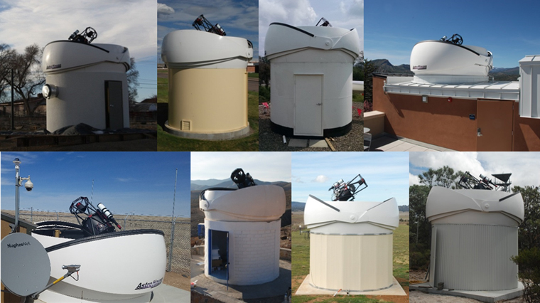
Figure 1. Eight FTN Observatories currently in operation. Top row: from left to right, the Falcon telescopes located at: Otero Junior College (La Junta, Colorado, USA); Northeastern Junior College (Sterling, Colorado, USA); The Pennsylvania State University (University Park, Pennsylvania, USA); and Fort Lewis College (Durango, Colorado, USA). Bottom row: from left to right, the Falcon telescopes located at Yoder, Colorado, USA; Mamalluca Observatory (Vicuña, Chile); University of New South Wales (Canberra, Australia); and Gravity Discovery Centre (Gingin, Western Australia).
Download figure:
Standard image High-resolution imageTable 1. The FALCON Telescope Network Global Distribution
| Education or Research Institute | Telescope Location (city, state) | Country | Longitude (east) | Latitude | Elevation (meters) | Avg Clear Nights per Year | Avg Sky Brightness at Zenith (mag/asec2) |
|---|---|---|---|---|---|---|---|
| USAF Academy | Woodland Park, CO | USA | 255.01 | 39.01 | 2790 | 168 | 19 |
| MITRE Corporation* | Yoder, CO | USA | 255.80 | 38.89 | 1961 | 168 | 19 |
| Colorado Mesa University | Grand Junction, CO | USA | 251.76 | 39.96 | 1380 | 176 | 21 |
| Fort Lewis College* | Durango, CO | USA | 252.13 | 37.27 | 1880 | 186 | 19 |
| Northeastern Junior College* | Sterling, CO | USA | 256.80 | 40.65 | 1177 | 164 | 20 |
| Otero Junior College* | La Junta, CO | USA | 256.46 | 37.97 | 1221 | 183 | 18 |
| Penn State University* | State College, PA | USA | 282.17 | 40.86 | 317 | 99 | 19 |
| Universidad de La Serena* | Vicuña | Chile | 289.32 | −29.99 | 1139 | 219 | 21 |
| University of New South Wales and EOS* | Canberra | Australia | 149.17 | −35.29 | 600 | 120 | NA |
| University of Western Australia, Catholic Education Western Australia, and Gravity Discovery Centre* | Gingin | Australia | 115.71 | −31.36 | 18 | 144 | 21 |
| Technische Universität Braunschweig | Braunschweig | Germany | 10.55 | 52.28 | 73 | 37 | NA |
| University of Cape Town (TBD) | Cape Town | South Africa | 18.46 | −33.96 | 110 | 161 | NA |
Notes. Asterisks indicate operational node. NA: not available.
Download table as: ASCIITypeset image
2.1. Optical Design and Structural Characteristics of Telescopes and Instrumentation
Even though there are currently various global arrays of optical telescopes, most of them are composed of systems with different optics or important instrumental differences. This may cause long-term temporal studies to present inhomogeneities that could affect their results. As one of the goals of the FALCON project is the simultaneous observation of the same object from distant locations, it was decided that the network would be composed of "cloned instrumentation," i.e., each FALCON node must be a true and accurate copy of the other nodes that make up the network (see Figure 2). In addition, each node must have the ability to be managed remotely from anywhere in the world or be autonomously tasked and controlled.
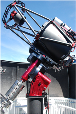
Figure 2. The Falcon telescope at Fort Lewis College as an example of what the system looks like after installation.
Download figure:
Standard image High-resolution imageTherefore, after considering factors such as the availability of instrumentation, exportability and ease of acquisition, geographic location, installation coordination and logistics, robotization, automation and remote control capability, and financing, the company Officina Stellare was selected as the main supplier. The selected telescope was the Pro RC 500 Ritchey–Chrétien model, which has a 0.5 m (20 inch) primary mirror, an f/8.1 focal ratio, and a 4000 mm focal length. The primary mirror is constructed using zero expansion Astro-Sitall glass, while the main tube is designed on the basis of a carbon and aluminum alloy. Focusing is achieved by moving the secondary mirror using the SkyX autofocusing feature for reaching optimal focus.
The telescope is on a Paramount ME2 (German equatorial mount) from Software Bisque. This type of mount locates the weight of the telescope and the counterweights in positions opposite to the main focus of the mount (or polar axis or right ascension axis), ensuring stability, versatility, and precision at the time of tracking.
The buildings that house the telescopes and control systems are covered by a 3.65 m diameter (12 foot diameter) fiberglass structure, with a clamshell aperture. The dome supplier is the company Astro Haven Enterprises. The building is the only component in the network that can be different. These are designed and built by the telescope host institutions, and respond to different needs and capabilities, mainly associated with the geography of each place or available financing and resources of the partner. For example, while it was chosen to build based on pre-formed concrete panels or with steel in some nodes, in Chile, due to its complex geography and high seismicity, it was selected to build based on reinforced masonry with an internal structure of steel and reinforced concrete beams.
Below is a list of hardware and software components for each FALCON telescope.
- (1)Hardware.
- (a)Officina Stellare 20 inch, f/8.1 Ritchey–Chrétien.
- (b)Apogee Alta F47: 1024 × 1024, 13 μm pixel, 11
 FOV (0
 65 pixel−1 or 50'' mm−1).
 - (c)Apogee 9-position Filter Wheel: B, V, R, g', r', i', z', 100 lines/mm diffraction grating, exoplanet filter.
- (d)Astro Haven 12-foot Clamshell Dome.
- (e)Boltwood Cloud Sensor II.
- (f)Symmetricom GPS Receiver (BC637PCIE): 170 ns rms accuracy (UTC), 100 ns clock resolution for time requests (sub-ms timing for computer applications).
- (g)Advantech Gen II Computers w/Intel SSD DC S3700 Series.
- (h)Synology NAS (8–20 TB).
- (i)Cisco ASA 5505 Router.
- (j)Cisco Small Business 200 Series Switch.
- (k)Tripp Lite Uninterruptible Power Supply (UPS) SMART1000/2000.
- (l)Foscam Pan/Tilt Internet Protocol (IP) Camera (FI8919W and FI9826W).
- (2)Software.
- (a)Software Bisque TheSkyX Suite.
- (b)FalconExec.
2.2. Detectors and Optical Filter Systems
The camera installed on all telescopes of the global FALCON network is an Apogee Alta SERIES model F47 brand camera. The camera is equipped with a 1024 × 1024 pixel E2V CCD47-10 sensor with back-illuminated architecture and a nominal distance of 13 μm between pixels. The sensor has a quantum efficiency of 52% at 400 nm and 96% at 500 nm. The sensor size is 13 × 13 mm (18.88 mm diagonal), where each pixel has a size of 13 μm. The sensor is cooled by thermoelectric coolers using a forced air system, reaching −25 °C. The typical plate scale of the system is 065 per pixel resulting in a field-of-view of approximately 11'.
Each telescope has an Apogee AFW50-9R filter wheel mounted on the Cassegrain focus of the telescope. The filter wheel structure allows the installation of 9 different circular filters of 50 mm in diameter. Selecting the best photometric system for a global array of telescopes is not a simple task. The global distribution of all FALCON nodes will allow the performance of a variety of astronomical projects, from searching for exoplanets by studying the curves of light in prolonged timescales, to searching for the electromagnetic triggers of gravitational waves. On top of this, we should add the capability of performing observations of the same object from different latitudes of the world co-temporally. This allows us to, for example, study the structural properties of geosynchronous satellites, thanks to the ability to detect various sections lit differently from symmetrically separated positions, due to the geometry of the rays that illuminate the satellites (see Section 4).
Based on these factors, a wide filter system was selected that is commonly used by the scientific community. This should allow us to easily calibrate the photometric data obtained by the different nodes, and create a homogeneous database in a relatively straightforward way. Two commonly used wide band photometric systems include: the Sloan prime photometric system u'g'r'i'z' and the Johnson–Cousins system. Considering the detector's quantum efficiency, we decided to use the following photometric filters: B, V, R, g', r', i', z'. The selection of these filters ensures acceptable transmission between 400 to 1000 nm. All the Johnson–Cousin and Sloan prime filters are 3 mm thick, thus minimizing the need to refocus the telescope when changing filters.
Additionally, we have an Astrodon ExoPlanet Blue-Blocking filter. This filter is also 3 mm thick and has anti-reflective layers on both sides of the filter. Furthermore, it is optimized for studying light curves in bright stars (brighter than magnitude 10), thanks to its ability to block UV radiation and the blue portion of the visible spectrum, generating excellent transmission at wavelengths greater than 500 nm. There are several benefits of using such a filter when conducting exoplanet transit photometry. First, mitigation of airmass extinction differences between target and comparison stars of different colors. Second, reduction of scattered moonlight into the optical path. Third, stellar limb darkening is weaker at longer wavelengths, yielding better estimates of second and third contact times during transit events.
The filter wheel also has a 100 lines per millimeter Richardson transmission diffraction grating (100 lines/mm, 4 6 blaze) in one of the slots. The diffraction grating's theoretical resolution is 103 < R < 147 for a wavelength range of 350 nm < λ < 700 nm. At first glance, slitless spectroscopy appears to be a rather unusual way to obtain satellite spectral information. Nonetheless, this method can be useful since it delivers many spectra in a single image. With our modest resolution, our spectrograph will deliver more usable information than images made using a set of BVR filters (10 times as many spectral channels since a filter in a BVR system typically has a full width at half maximum of 100 nm). We performed an analysis to determine the appropriate grating dispersion and considered the major sources of error. Since our cameras have a CCD chip size of 1024 × 1024 pixels with a 13-micron pitch, using a 100 lines/mm grating will allow us to image the zero order and the +1 order in a single frame. This allows co-temporal imagery of the spectrum from 350 to 850 nm.
3. Geographical Distribution of the Global FTN
One of the characteristics that transform the FTN into an astronomical observatory with unique features is the global distribution of the array of telescopes. The selection of sites to meet the special scientific needs was based on a series of parameters. First, the host locations of the FALCON nodes should ensure their operability through easy access to the essential technical resources for observatory operation (access, roads, electricity, water, Internet, among others). Second, the global distribution should respond with respect to the basic scientific needs of the FTN, i.e., places should be selected that allow simultaneous observations of the same object (primarily manmade satellites orbiting the earth) from different illumination geometries, the continuity of observations, and be able to immediately respond to astronomical alarms, among others. It should be noted that for cost and maintainability reasons, selecting locations based on pristine astronomical conditions was not a factor.
Thus, 12 sites that meet the requirements of site selection were selected throughout the world; seven of these are within the United States, one in the north of Chile, two in Australia, and one in Germany. The twelfth and final telescope is tentatively slated for a site in Cape Town, South Africa. Many FTN sites are located in Colorado to provide the ability to simultaneously observe the same low-earth orbiting (LEO) satellite from different vantage points and illumination geometries. The same reasoning applies to having a site in Chile at a similar longitude as the U.S. sites; however, in this situation it is to enable simultaneous observations of geosynchronous earth orbiting (GEO) satellites instead of LEO satellites. The simultaneous fields of regard for LEO and GEO satellites can be seen in Figure 3.
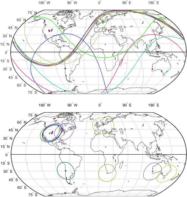
Figure 3. Field of regard coverage of the FTN for geosynchronous orbits (top panel) and low-earth orbits of 1000 kilometers (bottom panel).
Download figure:
Standard image High-resolution imageAll of the observatories are under the responsibility of various institutions, ranging from two-year colleges to advanced research centers and universities, and USAFA let each institution decide the specific location to build the observatory based on cost, operations, and maintenance considerations. In Table 1, we detail the 12 sites selected to be FALCON network hosts, including the host institution (column 1), the city, state, and country where the FALCON telescope is located (columns 2 and 3), the geographical coordinates in degrees (columns 4 and 5), the elevation of the telescope installation site in meters above sea level (m a.s.l, column 6), the average number of clear nights per year based on climate data from either site managers or from weatherspark.com (column 7), and the average dark time sky brightness at zenith where these data are available (column 8). Eight nodes are in operation at the time of writing this document (as indicated by an asterisk in Table 1).
The global distribution of the FALCON network enables the simultaneous observation of one object from different geometries. This unique capability is illustrated in Figure 3, in which the study of artificial satellites is addressed. In this figure, the different observation areas can be distinguished that are obtained from each telescope when it comes to LEO (right) and GEO (left) satellites. Fields were built for elevations over 20° above the horizon. As can be observed, the visualization of objects located in any part of the geosynchronous belt is possible from at least two sites. In some cases, it is even possible to perform simultaneous observations from the Northern and Southern hemispheres. For low-orbit satellites, the sites in the United States provide overlap with each other, as do the sites in Australia. In addition, the distribution of telescopes will allow object tracking to be passed from one telescope to the next; as the object moves out of the field of view for one telescope, another telescope can begin tracking it. Using this method, depending on the orbital parameters, the FTN will be able to track some satellites through their orbit in a greater temporal space in comparison with a single site by itself.
Below, we detail the main features of each of the sites that make up the global FTN.
3.1. Installed Falcon Telescopes
3.1.1. OJC-Falcon Telescope
The OJC-Falcon is located on the 40-acre campus of Otero Junior College (OJC), La Junta, Colorado, USA. Located approximately 145 miles (233 km) southeast of Denver, OJC is a two-year college, founded in 1941 and part of the larger Colorado Community Colleges System. Although the OJC-Falcon is located on campus and in the town of La Junta, the relatively small population of the city (∼7000) and a predominately agriculture economy lends itself well to fairly dark skies.
3.1.2. NJC-Falcon Telescope
The NJC-Falcon is located on the 34-acre north campus of Northeastern Junior College (NJC), at the northern edge of Sterling, Colorado, USA. Sterling is located approximately 125 miles (202 km) northeast of Denver. NJC is a two-year, public, community college, founded in 1941 as a district college and joined the Colorado Community Colleges System in 1997. The north campus location of the NJC-Falcon places it at the extreme northern edge of Sterling, a city of about 12,000 that is surrounded by agricultural land.
3.1.3. PSU-Falcon Telescope
PSU-Falcon telescope resides at The Pennsylvania State University, University Park campus. The University Park campus is located in the ridge-and-valley Appalachian Mountains (adjacent to Nittany Mountain) approximately 200 miles (320 km) northwest from Philadelphia and 140 miles (224 km) northeast from Pittsburgh. The telescope is housed in a roof-top observatory on top a facility managed by Penn State's Applied Research Laboratory (ARL), approximately three miles from the center of campus near the University Park airport.
3.1.4. FLC-Falcon Telescope
FLC-Falcon resides in the roof-top observatory on the new Geoscience, Physics & Engineering building (Sitter Family Hall) on the Fort Lewis College (FLC) campus in Durango, Colorado. Durango is approximately 340 miles (547 km) southwest of Denver. The FLC campus sits on a geological shelf above the town of Durango in the southwestern corner of Colorado.
3.1.5. MMO-falcon Telescope
The MMO-Falcon is inside a five-hectar area of the Mamalluca Observatory located in the Coquimbo Region, Chile. Bordering the southern end of the Atacama Desert, MMO-Falcon is positioned on the west side of the Andes mountain range, in the same mountain range in which some of the most important astronomical facilities of the world are located. It is three miles (5 km) away from the north of Vicuña (the closest city), and 45 miles (72 km) to the west of the city of La Serena, the city where the University of La Serena is located, a strategic partner of the USAFA in coordination with FALCON in Chile. The site is far from the main urban centers, ensuring low contamination by dust or luminosity.
3.1.6. CBR-Falcon Telescope
The CBR-Falcon telescope (Figure 4) is located at the University of New South Wales (UNSW) campus in Canberra, Australia, just 0.3 miles (0.5 km) away from the School of Engineering and Information Technology (SEIT) buildings. Light pollution in the area is very low as Canberra is a very widespread and not highly populated city, however the average zenith sky brightness has not been measured.
3.1.7. Pindan-Falcon Telescope
The Pindan-Falcon Telescope is located within the Gingin Gravity Precinct, which is located 50 miles (80 km) north of Perth, Western Australia. The site contains the University of Western Australia (UWA) gravitational detection node coordinated by the UWA School of Physics and is part of the Australian Consortium for Interferometric Gravitational Astronomy (ACIGA). In addition to a number of ongoing experiments in this area, many with international collaborators, the location is also the site of the Gravity Discovery Centre (GDC), which is an education and outreach facility to promote physics, researchers in physics and the teaching and learning of Einsteinian Physics.
3.1.8. YDR-Falcon
The YDR-Falcon is located near the small town of Yoder, Colorado approximately 38 miles (61 km) south east of the USAFA Cadet Area. The YDR-Falcon is part of a larger optical telescope complex on leased land. Unlike many of the other FALCON telescope observatories, the dome for the YDR-Falcon is not constructed as a two-level observatory, rather the dome is on a 12 inch riser and the dome base ring has an access hatch for entry and exit. Another difference between this telescope and other FALCON telescope is that this telescope is mounted onto a 30 inch sand-filled Software Bisque riser; other systems are typically mounted onto a 12 inch riser. The YDR-Falcon achieved first light on 2018 March 8.

Figure 4. CBR-Falcon Telescope in operation (long exposure picture).
Download figure:
Standard image High-resolution image3.2. Falcon Telescopes Under Construction
3.2.1. FRH-Falcon Telescope
The FRH-Falcon telescope is located on a 650-acre recreational area maintained and operated by USAFA, and located approximately 7 miles (12 km) west of the USAFA Cadet Area in the Pikes Peak region of Colorado. The observatory is already built and the Paramount ME2 is installed (Figure 5). However, to become fully operational, the telescope and all the hardware accessories need to be installed. We anticipate that the FRH-Falcon telescope will become operational in 2018.
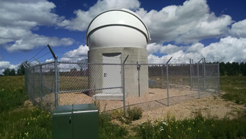
Figure 5. FRH-Falcon at the USAFA Farish Recreational Area, Woodland Park, Colorado.
Download figure:
Standard image High-resolution image3.2.2. CMU-Falcon Telescope
The Colorado Mesa University Falcon Telescope will be located at The Grand Mesa Observatory situated approximately 25 miles (19 km) southeast from downtown Grand Junction, Colorado and 181 miles (291 km) west of Denver. The observatory will be a shorter building constructed with concrete tiles; and instead of a concrete pier, we will use a 48 inch sand-filled riser attached to a concrete slab isolated from the building foundation (Figure 6). The construction of the observatory is underway and we expect it to be fully operational by 2018 August.

Figure 6. CMU-Falcon under construction at the Grand Mesa Observatory, Grand Junction, Colorado.
Download figure:
Standard image High-resolution image3.2.3. TUBS-Falcon Telescope
The TUBS-Falcon telescope will be installed at  longitude and
  latitude. The site is located north of Braunschweig, about 1.2 miles (2 km) from the Institute of Space Systems of the Technical University of Braunschweig. Due to the climatic conditions in northern Germany, the construction of a solid building is required. The building is currently under construction, as can be seen in Figure 7. You can see the reinforced concrete central body and the bottom panel, which are constructional decoupled from one another to reduce transmitted vibrations the telescope.
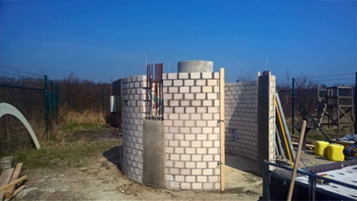
Figure 7. TUBS-Falcon under construction at Braunschweig, Germany.
Download figure:
Standard image High-resolution image4. Remote Control System of the Falcon Nodes
The FTN was designed to conduct observations for three main areas of interest: artificial satellite characterization, astronomy research, and K-12 education programs related to science, technology, engineering, and mathematics (STEM). This means that users of the FALCON network range from high school students, USAFA cadets and other university students, to researchers at higher research centers. Therefore, to ensure that all users could easily request observations and access the data acquired by any of the telescopes, and FTN team members could conduct maintenance and manual remote operations, it was necessary to design a safe and accessible network for the entire collaboration.
FTN control is housed on a USAFA Cadet Space Operations Center (CSOC) server and is based on an architecture designed to facilitate the remote use by multiple users. This permits easy maintenance and efficient response when testing new services or applying new control algorithms. The primary path for communication between the USAFA CSOC and each of the FTN network nodes is an HTTPS connection. We also designed a one-way system between the CSOC and the local internal network (FTN-LAN) of each of the observatories through a Virtual Private Network (VPN). This allows us to carry out maintenance, update programs, or manage the administrative tasks of controlling the observation processes. Figure 8 illustrates the communication scheme established between the CSOC and the FTN nodes.
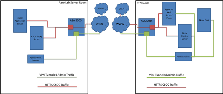
Figure 8. Communications between the USAFA CSOC (left) and an FTN observatory node (right).
Download figure:
Standard image High-resolution imageInside each observatory, communication between devices is mainly through USB, serial, coax, and category 5/6 Ethernet cables (CAT 5/6). Figure 9 illustrates the typical communication setup between various devices within a FALCON telescope observatory. The devices inside the observatories are all connected to uninterrupted power supplies (UPS) that have both remotely controllable electrical ports as well as non-controllable ones. The elements connected to the remotely operated ports include the Paramount ME2 mount, the telescope control computer, the dome, and other devices that are connected to a 12-Volt power supply (e.g., camera, filter wheel, telescope, and remote focus system). This allows remote operation (startup and shutdown) of all mechanical and electrical systems that make both observations and maintenance of the sites possible. All other components of the observatory (video cameras, climate monitoring system, communication switch, global positioning systems (GPS), among others) are connected to the non-controllable ports, ensuring non-intervention and a constant power supply. The telescope control equipment is generally located inside the buildings that house the telescopes, while data storage, computation, and communications equipment are housed in buildings close to the telescope, where they are secured in climate-controlled conditions.
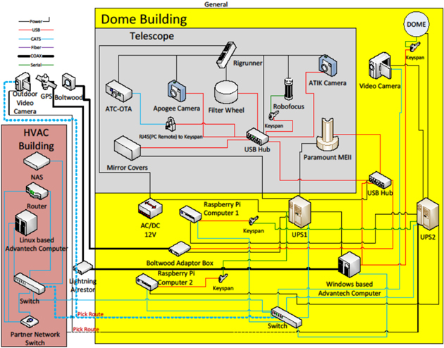
Figure 9. Typical FTN observatory node setup.
Download figure:
Standard image High-resolution imageDuring the implementation stage of the FALCON network, use of an individual telescope will primarily be through on-site operations or remotely through a remote desktop application. In the operational stage, users will submit observational requests and retrieve data through a web platform that is centralized in the CSOC. Currently, the requests are categorized into three types, Astronomical Catalog, Astronomical R.A./decl., and Satellite. Within these categories, the user designates the object, observation time, image exposure, filter, automatic dark image preferences, and the necessary location information as needed (i.e., TLE or R.A./decl.). The web platform will prioritize data acquisition based on the type of user, the target, and the priority that the user assigns to the observation. Depending on the object's observability, the optimal telescope will be assigned to perform the data acquisition; however, a user will also have the ability to designate specific telescopes, especially when trying to obtain simultaneous observations of a single target from multiple telescopes. A scheduling program will be designed to de-conflict requests made for the same time slot on a node and reschedule requests due to observation failure by weather, malfunction or a higher priority request. Then, the scheduler will assign an observation schedule to the respective node. Scheduled tasks will be sent from the CSOC to each telescope site at regular intervals. After scheduled tasks have been sent to the site, particular users will still have the ability to send time sensitive requests, containing an alert message, which will override the currently scheduled items as needed.
If weather conditions are favorable, the nodes will autonomously begin night operations. This process first involves powering on the equipment and transferring task files to the appropriate location for operations. The task files are then parsed by FalconExec for date, time, and object information. In addition, Falcon Exec calculates nautical sunset and sunrise, which become the startup and shutdown times of the telescope. When the startup time is reached, FalconExec communicates with the observatory control software SkyX to conduct the startup and then creates Orchestrate scripts for each task that SkyX can read. The data is saved automatically to the computer and sent to a data storage device. Both FalconExec and SkyX continually monitor the weather conditions, and a weather shutdown is conducted as needed. At the shutdown time, FalconExec tells SkyX to perform the appropriate shutdown actions.
At the end of each night of observation, the nodes will send the collected data to the central server. Each of the observation stages of a requested object will be reported to the user via the web interface, where downloadable files from the data set will be made available. It should be noted that although each FALCON telescope system is equipped with a GPS receiver, GPS is not currently being used to trigger camera shutter operations to enable precise simultaneous observations. To achieve simultaneous observations, Windows 7 computer clock is synched to GPS and the CSOC scheduler has to provide the exact task to multiple telescopes. Additionally, the automated scripting interface for SkyX does not currently support automated bias or flats. These, however, can be conducted manually outside the automated schedule using the remote desktop application. As we further develop and improve FTN automation, calibration data like biases, darks, and flats will become standard measurements and will be made available to all FTN users.
5. Early Science with the FTN
Although the FTN is still in the development stage, there are already experimental programs in process to test the capabilities of the network both in the area of studying satellites as well as in programs related to astronomical events in the nearby universe. Below, we describe the programs with the most progress to date and those that verify the potential of network once all nodes are operating and the data control system is completely developed.
5.1. Simultaneous Observations of Geosynchronous Satellites
The FTN was designed to achieve co-temporal, simultaneous observations of geosynchronous (GEO) satellites from multiple illumination geometries as illustrated in Figure 3. While the geosynchronous belt is becoming increasingly more populated, its importance to the national security of many countries is paramount. Due to the great distance at which the geosynchronous belt is located, satellites orbiting at that altitude are non-resolved, even using the largest telescopes. Therefore, to study the properties of these objects, techniques must be developed based on non-resolving observations and measurements using broadband photometry and low-resolution slitless spectroscopy. We have conducted some preliminary spectral observations of satellite glints (i.e., a specular reflection off of a satellite, usually its large solar panel arrays) from two different telescopes, the NJC-Falcon and a smaller 16 inch telescope located on the campus of USAFA (called USAFA-16). Figure 10 shows the raw images taken from the two telescopes of a cluster of GEO communication satellites seen in the skies above Colorado. The USAFA-16 (right panel image) has a slightly larger field of view than the NJC-Falcon and hence was able to capture four satellites in an image, whereas the NJC-Falcon only observed three satellites. The satellites in the NJC-Falcon image (left panel) from left to right are DirecTV-15, DirecTV-12, and DirecTV-10. The satellites in the USAFA-16 image (right panel) from left to right are DirecTV-15, DirecTV-12, DirecTV-10, and Spaceway-1. These measurements are now being analyzed by USAFA cadets (senior physics majors) as part of their capstone research project to determine relative power capacities of different satellite manufacturers (Dunsmore et al. 2016).
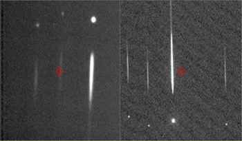
Figure 10. Simultaneous glint spectra of DTV-10 with 0.5 s exposure. LH-image from NJC-Falcon, RH-image from USAFA 16 inch telescope.
Download figure:
Standard image High-resolution image5.2. The Transient Optical Robotic Observatory of the South (TOROS Collaboration)
In 2016 February, the National Science Foundation (NSF) conducted a press conference in conjunction with the Laser Interferometer Gravitational Wave Observatory (LIGO) Scientific Collaboration (LSC), a partnership consisting of more than 1000 scientists from 16 countries, announcing one of the most important scientific discoveries in history: the detection of gravitational waves coming from the collision of two massive black holes 1.5 million light years away. The detection of this phenomenon not only confirms Einstein's General Theory of Relativity, but it is also the first direct detection of two colliding black holes. LIGO is a network of advanced ground-based gravitational-wave (GW) interferometers consisting of two widely separated installations within the United States located at Hanford, Washington and Livingston, Louisiana. The observatory is designed to be capable of detecting GWs emitted by the mergers of neutron stars and/or black holes in binary systems out to distances of hundreds of megaparsecs (see Abbott et al. 2016 and references therein).
In 2013 June, the LIGO Scientific Collaboration (LSC), the partnership that control the LIGO observatories and consisting of more than 1000 scientists from 16 countries, make a worldwide call to participate in electromagnetic (EM) and multi-messenger observations of GW events recorded by their detectors, using a wide range of telescopes and instruments of "mainstream" astronomy.
The recent GW events are the impetus for the creation of international collaboration dedicated to the detection of the electromagnetic counterpart of gravitational wave triggers. In this context, a new collaboration was established: the Transient Optical Robotic Observatory of the South (TOROS), a partnership composed of scientists from the Gravitational Wave Astronomy at The University of Texas Rio Grande Valley and astronomers at Texas A&M University in the United States, the National University of Cordoba in Argentina, the University of La Serena (ULS) and the Pontifical Catholic University in Chile, and the National Institute of Astrophysics, Optics, and Electronics in Tonantzintla, Puebla, Mexico (Benacquista et al. 2014; Diaz et al. 2014). The main objectives of the collaboration is to participate in observations of future detections of events detected by LIGO using a network of optical telescopes located in the southern hemisphere of the world, and to develop new facilities such as an astronomical facility in Cordon Macon, a mountain located in the Atacama highlands of northwestern Argentina. In 2016 August, the Universidad de La Serena, host institution of the MMO-Falcon signed a memorandum of understanding with the TOROS collaboration to include that node as an official instrument thus making the entire FTN an active member of the TOROS collaboration.
On 2017 August 17 at 12:41:04 UTC, a binary neutron star system (BNS) merger candidate was identified in data from the LIGO Hanford (H1) detector. The Gamma-ray Burst Monitor (GBM) on board Fermi (Bissaldi et al. 2009) detected an event ∼2 s after the GW trigger (designation GRB170817A). The optical transient was independently detected by multiple teams within an hour. This event corresponds to the first multi-messenger observations of a BNS merger, the trigger of the Gravitational Wave GW170817 (Abbott et al. 2017). TOROS participated in the search for the EM counterpart of GW170817 starting just a few hours after the trigger (Diaz et al. 2017). On the nights of August 17 and 18, we surveyed 26 nearby galaxies contained in the initial localization region using the MMO-Falcon. Additionally, ULS served as the hosting center for data taken by other telescopes also associated with TOROS.
5.3. Exoplanet Detection and Characterization
Employing the four sites that were operational in 2015–2016, a team of USAFA faculty members, cadets and civilian high school students explored the potential future utility of the FTN for detecting exoplanets via the transit method. This endeavor began with collecting photometric data over several hours during known transits of "hot Jupiters" with apparent magnitudes 9 < mv < 13 and transit depths >1% (∼10 mmag). Performing differential photometry with various COTS astronomical software packages, several transit signals were recovered at greater than 5σ statistical significance including a pair for the exoplanet TrES-3b from two different Falcon telescopes (Figure 11). TReS-3b is a 1.3RJupiter planet in a 1.3 day orbit around an apparent magnitude mV = 12.4 G-type star 400 parsecs from Earth. Note that the ordinate for the OJC plot is normalized flux (the required input of the EXOFAST fitting program), whereas the NJC ordinate is magnitude (as required by the JKTEBOP fitting program). As a result, the transit depth in normalized flux should be about nine percent smaller than the depth in magnitudes. We label the NJC ordinate as Δm to indicate that the magnitudes shown are differential magnitudes. The rms of the residuals is 0.0026 (normalized flux) for the OJC fit, and 2.7 mmag for the NJC fit. This exercise validated Falcon telescopes as a viable resource for follow-up observations on exoplanet candidates identified by ground-based wide-FOV surveys (e.g., TrES (Alonso et al. 2004), KELT (Pepper et al. 2007)), and the FTN has been identified as a potential future contributor to follow-up observations for the space-borne Terrestrial Exoplanet Survey Satellite (TESS; J. Pepper 2018, personal communication).
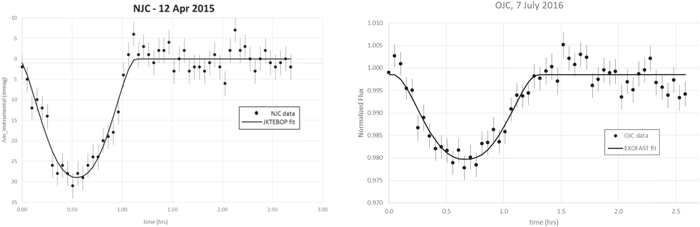
Figure 11. Hot Jupiter transit detection with 20 inch Falcon telescopes at NJC-Falcon (left plot) and OJC-Falcon (right plot) using the Johnson–Cousins V filter and 180 s exposures.
Download figure:
Standard image High-resolution imageFurther data collection focused on smaller planets (1–3REarth) orbiting "ultra-cool dwarf" (UCD) stars (spectral type M4-M9), congruent with ongoing efforts using sub-1 m ground-based telescopes to detect terrestrial exoplanets residing in their host stars' habitable zone (e.g., MEarth Nutzman & Charbonneau 2008, TRAPPIST Gillon et al. 2016). The population of known planets with these characteristics is significantly smaller than that of hot Jupiters, limiting the sample set to a pair of objects discovered by MEarth: GJ1132b (1.3REarth, M4 host star) (Berta-Thompson et al. 2015) and GJ1214b (2.7REarth, M5 host star) (Charbonneau et al. 2009). Transit detection for GJ1132b proved unachievable with the FTN at this point, given observed transit depths of less than 5 mmag (Berta-Thompson et al. 2015). However, Figure 12 depicts the successful recovery of a 5σ transit signal for GJ1214b collected by OJC-Falcon. Predicted transit values are duration = 52.1 minutes, depth = 14.9 mmag Berta et al. (2011); transit values recovered from the OJC-Falcon data are duration = 55 minutes, depth = 23.1 mmag. The missing data and fit line before and during ingress, as well as post-transit, were due to passing clouds (and corresponding low SNR). The rms of the residuals for this fit is 3.75 mmag.

Figure 12. GJ1214b transit detection with OJC-Falcon, 2016 June 6, using the Astrodon "exoplanet" filter8 and 90 s exposures.
Download figure:
Standard image High-resolution imageAdditional data was gathered from multiple FTN sites on a variety of different UCDs (not known to host exoplanets) to assess photometric precision and light curve stability over several hours of continuous observation. Using these results alongside theoretical analyses based on known system specifications, design parameters were developed for a hypothetical stand-alone UCD transit monitoring campaign. With optimistic assumptions regarding weather and dedicated telescope time, this study predicted that a campaign targeting M5-type UCDs with the full 12-node network would yield its first discovery of a new 1–2REarth exoplanet within approximately 80 nights of observing. Less optimistic assumptions extend that timeline by a factor of two or three. USAFA faculty and cadets researchers continue to refine both observational and analytical techniques in preparation for making substantive contributions to the exoplanet community as the FTN proceeds toward full operational capability.
5.4. Small LEO Satellites Characterization and Attitude Detection
UNSW Canberra Space, an Australian leader in Space Research has a wide portfolio of space missions and space research and development activities. The UNSW Canberra FTN node is central to the group's research in Space Situational Awareness. In 2017 November, The UNSW Canberra Space group and Defence Science and Technology Group (DSTG) launched the jointly owned and operated BRMM (Buccaneer Risk Mitigation Mission) CubeSat. The growth of this group and Australian space activities in general has been influenced by participation in the FTN. Two more small satellites missions are being designed and built by UNSW Canberra Space and scheduled to be launched during 2018 and 2019 sponsored by the Royal Australian Air Force (RAAF).
The Space Surveillance team of UNSW Canberra Space have been performing systematic and exhaustive observations of Buccaneer and other CubeSats (Figure 13). Observing CubeSats in Low Earth Orbit (LEO) is a challenging task due to their very small size and the strong uncertainties in their orbital information. They are affected considerably by space weather events and atmosphere density changes. As part of an ongoing research effort, UNSW Canberra Space has been able to measure attitude slew on specific CubeSats in the context of building up a photometry database on over 75 CubeSats. A particularly important example of this is the use of the CBR FTN to make first optical observation of the 2017 February launch of 104 satellites out of India into low earth orbit.
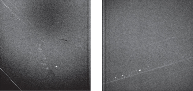
Figure 13. Buccaneer cubesat, 5 s exposure, exo filter 2018 January 15 (left); Flock 3P constellation (Planet) 8 hours after launch, 6 s exposure, exo filter 2017 February 15 (right).
Download figure:
Standard image High-resolution imageSimilarly observing from geographical location different to the other nodes, we are able to analyse satellites in GEO of the likes of AMC-9 and Telkom-1 which are non-consistent in their position, and hence visible at times from longitudes other than their apportioned slot in the GEO belt. Such opportunity sponsors international collaboration in the surveillance of space.
6. Education and Community Outreach Programs
One of the most effective ways of awakening the community's interest in science, technology, engineering, and math (or STEM programs) is through practical experiences. Moving from classical theory and behavioral teaching to a more modern teaching methodology is a high priority task in today's society where the emergence of digital systems compels a change in the teaching paradigm.
6.1. The STEM First-light Project
In order to combine the technology that we have available in the global FALCON network with the need to bring knowledge to the communities housing the different network telescopes, the FTN STEM First Light Project was designed. The First Light Project provides an opportunity for students, as part of a class or other educational group, to propose which objects will be the first outreach observations of an FTN node. It has been held for six of the eight currently operational sites, with the plan to conduct such an event for every FALCON telescope. A representative of each node works with the USAFA FTN outreach lead to identify teachers, schools, or organizations in their local area that focus on STEM related subject matter and invite them to participate. The project allows students to walk through the process of determining which astronomical objects would be interesting to observe and developing a technically sound proposal.
To provide one location where teachers can register for the event, acquire all of the needed event information, and submit their students' proposals, an online event software is used. The prospective teacher participants are provided with a link to the webpage where they can find all of the project details and guidance for submitting a proposal. For example, a document titled "How to Begin Your Proposal" helps teachers answer a series of standard questions such as is your target (or targets) visible at all from the designated FTN site? What time of year and what time of night is best for observing your target (or targets)? Is your target (or targets) well matched to the capabilities of the telescope and camera system? Also provided are a proposal template and a list of astronomy-related resources.
Once the FTN team receives the proposals, pre and postgraduate students along with FTN scientists evaluate the proposals and determine the feasibility of conducting them based on the characteristics of each site. After determining which proposed objects can and will be observed, FTN team members contact the students and teachers to discuss their proposals, provide interesting facts about their proposed objects, talk about the FTN, and answer their questions. To date, we have completed First Light Projects for six of the eight installed telescopes resulting in the participation statistics provided in Tables 2 and 3.
Table 2. Overall Participation Information
| Site | Total Proposals | Total Classes/ Teachers | Students Involved | Grade Levels |
|---|---|---|---|---|
| OJC | 8 | 5 | 57 | 6–12 |
| NJC | 9 | 4 | 89 | 10–12 |
| PSU | 19 | 9 | 202 | 7–12 |
| CBR | 35 | 10 | 174 | 7–12 |
| MMO | 26 | 8 | 116 | 3–12 |
| FLC | 18 | 5 | 102 | 6–12 |
Download table as: ASCIITypeset image
Table 3. International School Participation Information
| Site | Total International Proposals | Total International Schools | Chilean Proposals | Australian Proposals | Chilean Schools | Australian Schools |
|---|---|---|---|---|---|---|
| CBR | 14 | 4 | 0 | 14 | 0 | 4 |
| MMO | 10 | 4 | 2 | 8 | 2 | 2 |
| FLC | 7 | 2 | 0 | 7 | 0 | 2 |
Download table as: ASCIITypeset image
The proposed first-light objects fell within a variety of different categories, the most popular being solar system objects, as is seen in Table 4. Several of the proposals, especially during the projects using the Vicuña, Chile (MMO), Canberra, Australia (CBR), and Durango, CO (FLC) sites, indicated that in depth analysis would be completed upon receiving the data. Included in those studies were an exoplanet transit (WASP-43), orbital mechanics and laws of physics investigations based on multiple observations of the Saturnian and Jovian moon systems, open versus globular cluster studies, a comparison of stellar spectra, and galactic classification using the Hubble Classification Scheme. In addition, the international aspect of the projects allowed students to observe portions of the sky that may not typically be visible to them, for example, students in the US were able to observe Southern Hemisphere objects.
Table 4. Proposed Objects
| Object Type | Proposals |
|---|---|
| Stars | 17 |
| Solar system objects | 43 |
| Nebulae | 17 |
| Galaxies | 11 |
| Clusters | 16 |
| Distant exotic objects (ie., pulsars and quasars) | 2 |
| Exoplanet transit | 1 |
| Satellite | 5 |
Download table as: ASCIITypeset image
Examples of the resultant data images from the MMO and CBR first-light proposals that we provided back to the students can be seen in Figures 14–17. As we proceeded through all the sites' STEM First Light Projects and improved our capabilities, the provided data improved in quality and began including color-stacked images. Examples from the three prior projects can be found in a previous paper (Gresham et al. 2016). The data files sent to participating teachers are accompanied by an explanation of the filters used, viewing conditions, and any other information we feel the teacher could use to expand the students' understanding. We also offer to hold a teleconference with the classes to provide verbal feedback and to answer any questions they might have in regard to the images they received.
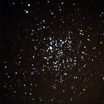
Figure 14. Wild Duck Cluster (MMO-Falcon).
Download figure:
Standard image High-resolution image
Figure 15. Jovian System (MMO-Falcon).
Download figure:
Standard image High-resolution image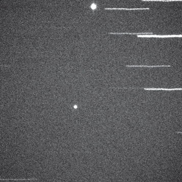
Figure 16. Intelsat 8 and Intelsat 805 (CBR-Falcon).
Download figure:
Standard image High-resolution image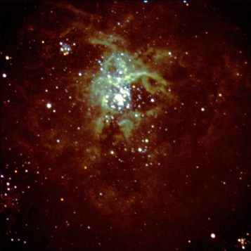
Figure 17. Tarantula Nebula (CBR-Falcon).
Download figure:
Standard image High-resolution image
6.2. Teacher Feedback
To conclude each event, we ask the teacher participants to complete a voluntary survey on the educational effects and project design. Overall, the results have indicated an improvement in student interest and understanding while also meeting the teachers' educational needs. To summarize the educational results tallied for all the sites' First Light Projects,
- 1.Over half of the responding teachers stated that the project helped them meet state or national education standards with about one third indicating they did not know.
- 2.On a 1–5 scale (strongly disagree to strongly agree), the average score was a 4.29, between Agree and Strongly Agree, when asked if the project improved the students' interest in science, astronomy, or other STEM subjects.
- 3.On a 1–5 scale (strongly disagree to strongly agree), the average score was a 4.29, between agree and strongly agree, when asked if the project met the teachers' expectations with respect to educating their students.
Previous project feedback pertaining to project design and the logistics of obtaining supplemental information and submitting proposals has been mixed. However, over time it has become more positive. We have improved user experience continually based on feedback from previous events. (Gresham et al. 2016).
7. Conclusions
We present a new global array of small aperture optical telescopes in this study, designed to study artificial satellites and the nearby universe: the FTN.
The FTN is developed by the Center for Space Situational Awareness Research in the Department of Physics at the USAFA and is composed of 12 telescopes located on four continents, capable of providing world class data on man-made satellites and astronomical objects (images and spectra).
Each FTN node includes an Officina Stellare Ritchey–Chrétien telescope Pro RC 500 model, with a 500 mm (20 inch) primary mirror, an f/8.1 focal ratio, and a 4000 mm (160'') focal distance, a Software Bisque Paramount ME2 mount, an Apogee AFW50-9R filter wheel mounted on the Cassegrain focus, equipped with broadband Sloan-prime filters g', r', i', z' as well as another three filters of the Johnson–Cousins photometric system (B, V, R). In addition, each filter wheel has a Richardson diffraction grating (100 lines per mm) and an Astrodon filter to detect exoplanets.
Each observatory is an exact replica of the others and has been optimized to study low-altitude artificial satellites, to identify and characterize geosynchronous satellites based on simultaneous observations from different latitudes of the world, and to study astronomical sources in the nearby universe. At the time of presenting this study, eight FALCON nodes are in full operation in the United States, Chile, and Australia. Another three nodes are under construction, with different states of progress.
The FTN was designed under the concept of remote and robotic operation. Both the observation application as well as the raw data obtained in any of the FALCON nodes will be accessible to FTN partners through an automatic acquisition system, and archived in the USAFA Cadet Space Operations Center. FTN users can submit observation requests through a web interface. Then, the requests are prioritized according to the type of user, target, and priority. A schedule for performing the network observation projects will be created at regular intervals, and each FTN site will autonomously run the section of the program that it is assigned. After completing a specific observation program, the FTN user will receive a notification that their data has been observed and they will be provided with a link to the data.
Finally, the FTN offers a wonderful opportunity to perform STEM programs for students and teachers around the world. In the first stage, extension and community outreach programs have been carried out under the "First Light" project, which seeks to implement scientific programs in the schools of the various communities that house the different FALCON nodes. Students and teachers from the schools in the communities in which the different FALCON nodes were installed submitted a scientifically sound proposal in collaboration with FTN scientists, allowing students and teachers to acquire experience in developing and implementing first-rate scientific programs.
The FTN is an ambitious effort. However, it demonstrates that through cooperation between multiple scientific and educational institutions, scientific programs of the highest level can be performed around the world in order to bring knowledge to all mankind.
The authors acknowledge the support of the administrative leadership of each partner institution. Funding for the telescope equipment and dome was provided by the United States Air Force Academy and the Air Force Office of Scientific Research (DURIP grant #F1ATA01222G001).
The following author's affiliation with The MITRE Corporation (W. Mandeville, S. Bygren, C. Randall, K. Schafer, and T. McLaughlin) is provided for identification purposes only, and is not intended to convey or imply MITRE's concurrence with, or support for, the positions, opinions, or viewpoints expressed by the authors. J.L.N.C. is grateful for financial support received from the Programa de Incentivo a la Investigación Académica de la Dirección de Investigación de la Universidad de La Serena (PIA-DIULS) and the financial support from the GRANT PROGRAMS FA9550-15-1-0167 and FA9550-18-1-0018 of the Southern Office of Aerospace Research and development (SOARD), a branch of the Air Force Office of the Scientific Research International Office of the United States (AFOSR/IO).
Installation of the Pindan-Falcon telescope was only possible through the major contribution of George Allingame of Pindan Constructions (thus acknowledgment in the name), and his team led by Paz Porter and Mitchell Bailey who designed and constructed the telescope facility. In addition, we thank Daniel Mills and Jim Grafham from Red Broadband who contributed all the internet connections, and whose efforts enabled the telescope to be commissioned, along with George Grant who provided the lifting services for the installation of the dome and telescope.
The Pindan-Falcon telescope was partially supported by an Australian Research Council (ARC) Linkage Project Einstein-First, which is endeavouring to introduce Einsteinian Physics early in the school curriculum. The Einstein-First project is led by the University of Western Australia in collaboration with Curtin University, Edith Cowan University, the Gravity Discovery Centre and the Graham (Polly) Farmer Foundation. Finally, the authors thank the reviewer for the comments and recommendations that improved this paper. The contents of this paper are approved for public release; distribution unlimited (USAFA-DF-2018-257; MITRE Case Number 18-1599).