

Abstract
The angular momentum carries crucial information on the physical nature of quantum matter. We propose and analyze MEMS gyroscope techniques suitable for measuring the angular momentum of mesoscopic quantum matter specimens at low temperatures. We bear in mind that it is not always possible to implement mode-matched gyroscopes, which we will refer to as degenerate gyroscopes, for the maximal signal sensitivity for these applications due to the constraints given by the cryogenic environment and the types of samples available for experiments. Because the analysis of non-degenerate gyroscopes in the literature is somewhat limited, we analyze and compare the ultimate angular momentum sensitivity of both degenerate and non-degenerate gyroscopes under amplitude and frequency modulation operation. Calculation based on our prototype device shows that the frequency modulation extends the operational range and improves sensitivity at low temperatures.
Export citation and abstract BibTeX RIS

Original content from this work may be used under the terms of the Creative Commons Attribution 4.0 licence. Any further distribution of this work must maintain attribution to the author(s) and the title of the work, journal citation and DOI.
1. Introduction
Intrinsic angular momentum of matter emerges from the microscopic physics inside condensed matter systems. For example, ferromagnets have intrinsic angular momentum originating from ordered electrons' angular momentum [1, 2]. In superfluids, a persistent mass current is measured as angular momentum for both 4He [3] and 3He [4, 5]. Quantum vortices naturally carry angular momentum in superconductors [6], superfluids [7–10], and even in lights [11]. There is a theoretical expectation that Wigner crystals in the quantum Hall system possess a macroscopic angular momentum in their bulk [12]. Recently, researchers have speculated that chiral topological superconductors/superfluids carry an intrinsic angular momentum as well [13–15], and there has been a long-standing debate regarding how large this angular momentum should be, commonly referred to as the angular momentum paradox [16, 17].
Although there have been several attempts to directly measure the intrinsic angular momentum [1–5,9,10,17–19], the mechanical nature of it introduced experimental difficulties hindering the measurement of its absolute magnitudes. Instead, researchers have utilized the inverse effects [20–22] or indirect evidence from nuclear magnetic resonances [23] or x-ray diffractions [24–26] to study the intrinsic angular momentum.
To measure the intrinsic angular momentum of quantum matter, it is necessary to employ experimental techniques that are compatible with low temperatures and mesoscopic specimen size to preserve the quantum effects. Microelectromechanical systems(MEMS) have been developed and adopted widely in the sensor industry [27]. Miniaturization not only gives small footprints but improves sensitivity and reduces the power consumption of these mechanical sensors. These characteristics of MEMS sensors are significant advantages for low-temperature applications, and this fact leads to the idea of MEMS gyroscopes for studying the intrinsic angular momentum of quantum matter.
To demonstrate this, we present a prototype gyroscope designed to directly measure the angular momentum of mesoscopic condensed matter systems which could potentially be used for experiments similar to that proposed in [17]. We adopted magnetomotive actuation and detection for its simplicity in device fabrication, transfer, or deposition of condensed matter samples and operation at low temperatures. We discuss the operational principle and the constraints of the gyroscope. Then we estimate the ultimate sensitivity of the gyroscope based on the room temperature characterization of the prototype device. This calculation complements the [17] with the inclusion of frequency-based operational mode and thermomechanical noise. Interestingly for non-degenerate gyroscopes, the sensitivity strongly depends on the choice of operational mode between amplitude-based and frequency-based detection. Therefore, one should choose the operational mode carefully based on the device parameters. Our analysis can be translated to other gyroscopes for condensed matter systems.
2. Operational principle
A MEMS gyroscope is a system of two orthogonal oscillators and a coupling mechanism between them. The coupling mechanism can be a Coriolis force from the movement of the gyroscope or the precession from the angular momentum changes. In the case of a condensed matter sample with intrinsic angular momentum, the intrinsic angular momentum provides the coupling as long as the angular momentum is oriented in the desired direction. For a simple plate geometry with two orthogonal torsion modes, as we adopt in our prototype device, the angular momentum must be perpendicular to the plate.
While degenerate condition—matching the resonance frequency of the two orthogonal oscillator modes of the gyroscope—is preferable in terms of the sensitivity for a gyroscope, tunability of the resonance frequencies is sacrificed in these condensed matter applications. An open-top device is preferred as a sample needs to be deposited or transferred onto the gyroscope plate and capacitive tuning is prohibited. Furthermore, the limited space in a cryogenic environment constrains the number of wiring for electrical access to the device. Therefore the devices often operate in the non-degenerate condition in these types of experiments.
The prototype gyroscope presented in this work is a silicon nitride(SiNx , low-stress LPCVD nitride) membrane trampoline resonator with a large plate and four identical strings holding the plate at the corners. The strings support a sufficient torsional motion of the plate with negligible bending. (see figure 1(b)) Figures 1(c), (d) show two torsional modes where one is oscillating about the x axis and the other about the y axis. We will refer to each mode as mode-x and mode-y.
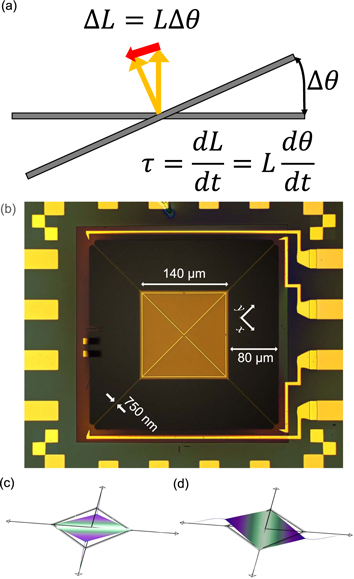
Figure 1. (a) A sketch describing how angular momentum couples two torsional modes. (b) Micrograph of a prototype gyroscope used for sensitivity estimation. The device is made of 100 nm thick silicon nitride on a silicon wafer. The center plate (light brown) is 140 μm × 140 μm square and is suspended by four bridges at the corner. The bridge has a width of 750 nm. Yellow outline around the plate and diagonal lines across the plate are the two electrodes patterned to actuate and detect the mechanical modes along with additional metallic patterns in place to maintain the four-fold symmetry of the device as closely as possible. The connectivity of the electrodes is shown in figure 2. We label the x and y axes to indicate the torsional axes. (c), (d) Two torsional mode shapes along the x and y-axes.
Download figure:
Standard image High-resolution imageMagnetomotive actuation and detection [28] is a relatively simple and sensitive technique with a straightforward conversion between electric signals and mechanical motions. To implement the magnetomotive technique, a magnetic field must be applied and electrodes must be deposited in a specific geometry. The current through the electrode-x(y) along the red(blue) line in figure 2 exerts torque that excites mode-x(y) while inducing negligible cross-talk between the two modes.

Figure 2. Circuit diagram of the measurement setup. A magnetic field is applied in the diagonal direction to the device. Electrode-x(y) is indicated with a red(blue) visual guideline. When AC currents flow through the electrode-x, magnetomotive force is induced and drives the mode-x. If there is an angular momentum perpendicular to the plate, the motion of mode-x actuates the mode-y and generates the electromotive voltage across the electrode-y. The generated signal can be detected by the lock-in amplifier.
Download figure:
Standard image High-resolution imageLet us now assume that we place a specimen with an intrinsic angular momentum along the direction perpendicular to the plate. If one of the torsional modes is excited, the angular momentum vector is tipped back and forth along with the oscillating specimen. The resulting change in the direction of the angular momentum produces torque that excites the other torsional mode, as in figure 1(a). The angular displacements of mode-x and y are denoted as θx and θy , respectively. The equations of motion of the two torsional modes read,


where Ix(y), bx(y), kx(y) and τx(y) are the moment of inertia, torsional damping, torsional spring constant, and applied torque for the oscillation about the x(y) axis. L is the angular momentum of the specimen along the direction perpendicular to the plate. The resonant angular frequency ωx(y) is given by  and the quality factor Qx(y) is Ix(y)
ωx(y)/bx(y) [27].
and the quality factor Qx(y) is Ix(y)
ωx(y)/bx(y) [27].
An oscillating current  driven through the electrode-x generates a torque τx
= BiAx
to the mode-x. Here, Ax(y) is the effective area under the electrode-x(y) that magnetic flux passes through when the plate is tilted. The torque tilts the whole plate along with the specimen and induces a change of angular momentum
driven through the electrode-x generates a torque τx
= BiAx
to the mode-x. Here, Ax(y) is the effective area under the electrode-x(y) that magnetic flux passes through when the plate is tilted. The torque tilts the whole plate along with the specimen and induces a change of angular momentum  that is equivalent to generating torque to the mode-y. As we drive mode-x at the resonant frequency of mode-y, mode-y will oscillate with amplitude of
  . The motion of the mode-y induces voltage from the Faraday induction law given by
  . The resultant voltage across the electrode-y is

Exact schemes vary from one system to another, but this kind of detection of the motional amplitude is the basic working principle behind many conventional gyroscopes. We will refer to such an operation scheme as an amplitude modulation (AM) mode. In a special case, if two modes are degenerate, i.e. ωx = ωy , the voltage signal is boosted by the quality factor of both modes, Qx and Qy , and hence sensitivity is improved. We will refer to this case as degenerate gyroscopes, as opposed to non-degenerate gyroscopes with ωx ≠ ωy .
An alternative approach is to treat the gyroscope as a coupled oscillator, as delineated by (1) and (2). One can recognize that the resonant frequencies of each mode should be shifted depending on the magnitude of angular momentum L. Frequency modulation (FM) gyroscope, sometimes called frequency output gyroscope, is designed to exploit this very feature [29, 30]. Despite the obvious connection between the amount of frequency shift and the magnitude of the angular momentum, FM operation is not widely employed since the benefit of such a new scheme is not obvious. In this paper, we analyze the performance of FM operation in detail and compare it to AM operation in an attempt to understand the advantages and disadvantages of each operational method.
We start our analysis by converting the (1) and (2) into a dimensionless form by rescaling each term according to  ,
,  ,
,  , gx(y)=L/Ix(y)
ωx
, ωr
= ωy
/ωx
,
, gx(y)=L/Ix(y)
ωx
, ωr
= ωy
/ωx
,  and
and  . θ0 is a normalization constant for angular displacements. We also set
  and τy
= 0 then convert to a dimensionless form by
and τy
= 0 then convert to a dimensionless form by  .
.


The solutions to these equations can be found either by direct diagonalization or numerically.
2.1. FM gyroscopes with degenerate torsional modes
For the initial analysis, we focus on a perfectly symmetric and degenerate gyroscope as the comparison with the AM gyroscope is more straightforward. We set  , Ix
= Iy
= I, gx
= gy
= g and ωx
= ωy
= ω0. In the case of b = 0 and τ = 0, eigenfrequencies of this coupled system ω± are exactly calculated to be
, Ix
= Iy
= I, gx
= gy
= g and ωx
= ωy
= ω0. In the case of b = 0 and τ = 0, eigenfrequencies of this coupled system ω± are exactly calculated to be

In the small g limit, which is an appropriate limit for small angular momentum, dimensionless eigenfrequencies ω± linearly depend on g = L/I ω0 as,

From the definition of g, one can easily identify that the frequency shift of the mode-x, δ ωx , is proportional to the magnitude of the angular momentum of the specimen as L = 2Ix δ ωx .
Introducing small damping factors to the equation does not affect this linear dependence of the resonant frequency shift with the angular momentum. Figure 3(a) and (b) map the amplitude and phase of each mode for a varying coupling constant, g, with fixed damping  and torque
  . The linear dependence of the resonant frequency shift is clearly shown.
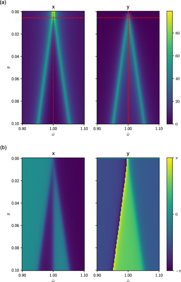
Figure 3. Amplitude (a) and phase (b) of the mode-x and mode-y of a degenerate gyroscope obtained by numerical simulation. The damping coefficient is set to  . Two bright peaks split out from
  .
.
Download figure:
Standard image High-resolution imageThe conventional AM gyroscope relies on the detection mode's amplitude increasing linearly with the angular momentum at fixed drive frequency and amplitude. But this breaks down when g becomes larger than  , as shown in figure 4(a). The amplitude of the mode increases with the angular momentum up to
  , peaks at around
  , and then starts to decrease. The usefulness of the AM gyroscope is thus limited by
  . This severely limits the operational range of AM gyroscopes, especially for high quality factor (small
  ) devices. This originates from the resonant frequency running away from the measurement frequency parked at the original frequency ω0.
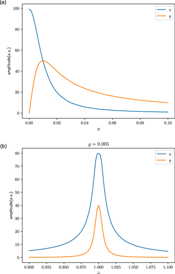
Figure 4. (a) Amplitude of mode-x (blue) and y (orange) when driven at the angular frequency  . Mode-y amplitude increases linearly with the angular momentum for small values of g and thus can be used to measure the magnitude of angular momentum. However, due to the limited region of this linear dependence, AM operation works only in a narrow region of
  . (b) The amplitude of mode-x and y at fixed g = 0.005. Only a single peak is observed and the frequency splitting due to the couple of mode-x and y is not yet identifiable. The data are extracted along the red vertical dashed lines and horizontal dashed lines marked in 3(a) and (b).
Download figure:
Standard image High-resolution imageOn the other hand, an FM gyroscope is also not sufficient to cover all ranges of g. When  , the two resonant frequencies overlap and we cannot distinguish them as shown in figure 4(b). This corresponds to measuring along the horizontal dashed line in figure 3(b). The limitations for each of the two methods are quite clear and this means one cannot operate a gyroscope continuously as either an AM gyroscope or an FM gyroscope for all values of angular momentum. One has to crossover from an AM gyroscope for small values of g to an FM gyroscope for
  .
.
2.2. FM gyroscopes with non-degenerate torsional modes
Due to the fabrication error and material inhomogeneity, a slight frequency-mismatch between the two seemingly degenerate modes is unavoidable in real devices, i.e. ωr
= ωx
/ωy
≠ 1. Once again, we start by solving for the equations with no damping, 

Without loss of generality, we can set ωr to be smaller than one. In the small g limit, equation (8) becomes approximately


where we assumed g ≈ gx ≈ gy . One can see that the frequency shifts on coupling constants g quadratically. Angular momentum can be calculated from the frequency shift δ ωx according to

where we assumed ωx + ωy ≈ 2ωx .
We now solve these equations numerically for a finite value of  . In figure 5(a), (b), we show the amplitude and phase map for different values of g and ω as in the degenerate case. Frequency shift shows a quadratic dependence for small values of g. As g grows larger, the frequency shift asymptotically approaches linear deviation by equation (8).
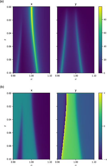
Figure 5. Amplitude(a) and phase(b) of the mode-x and mode-y of a non-degenerate gyroscope obtained by numerical simulation. The damping coefficient is set to  .
.
Download figure:
Standard image High-resolution imageIn an AM gyroscope, mode mismatch decreases the sensitivity since the driving efficiency is quickly suppressed by the Q factor when two modes are away from each other. In an FM gyroscope, mode mismatch also deteriorates the sensitivity but the mechanism is quite different. The quadratic dependence of the frequency shift at a small g limit reduces the sensitivity and it recovers the linear dependence at a large g, which is an advantage compared to the AM gyroscope. Moreover, unlike the degenerate case, one can distinguish the position of the peak even in the  region when the gyroscope is non-degenerate.
3. Sensitivity estimation
Here we estimate the sensitivity of the gyroscope based on a prototype device. Various sources of fluctuation can affect the sensitivity of mechanical resonators [31, 32]. At low temperatures, e.g. below 4K, most gas molecules are frozen, and hence fluctuation from residual gas would be negligible. Although experimental data on the thermal properties of a silicon nitride nanobeam are limited [33, 34], temperature fluctuation is expected to be comparable to thermomechanical fluctuation at 300 mK.
4
Temperature fluctuation of the device will only be further suppressed relative to thermomechanical fluctuation since the spectral density of the temperature fluctuation is proportional to T2 while that of thermomechanical fluctuation is proportional to T. Therefore, for experiments carried out below 300 mK, the main source of uncertainty should be thermomechanical fluctuation and measurement voltage fluctuation also known as circuit noise. Often the voltage fluctuation is dominated by amplifier input noise. The input noise of currently available commercial lock-in amplifiers is typically around 4 nV/ and we will adopt this value as our guideline. In the following sections, we will focus our attention on thermomechanical fluctuation and measurement voltage fluctuation to estimate the sensitivity of a low temperature gyroscope.
AM and FM operation requires extracting the amplitude and frequency of the gyroscope oscillation, respectively, from the raw voltage data. So the direct comparison of the signals is not straightforward. For easy comparison of the signal sensitivity, we will convert all our estimations into the magnitude of angular momentum δ
L in units of ℏ. The ultimate sensitivity must be determined for an individual device with various sources of noise being operated in different modes. For a given device, the noise sources, be it thermomechanical fluctuation(T) or circuit noise(C), will be denoted with subscripts as δ
LT
and δ
LC
, and the operational modes, AM or FM, will be denoted with superscripts as δ
LA
and δ
LF
. Whether a device is degenerate or non-degenerate will also be denoted with superscripts δ
Ld
and δ
Lnd
, respectively. For a given device, the largest noise source among  ,
,  ,
,  , and
, and  will ultimately limit the minimum detectable angular momentum.
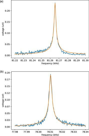
For sensitivity estimation, the actual parameters of the device are needed. We calculated the effective torsional moment of inertia from the known geometry and dimension of the device. The quality factor, resonant frequency, effective area, and maximum displacement can be extracted from the measurement of the resonance curves of the device in figure 6. The measurement was done at room temperature. Extracted parameters are listed in table 1. We detailed the calculation and measurement setup in the supplementary data.
Figure 6. Resonance curve of the mode-x(a) and mode-y(b) with 0.5 nA excitation current.
Download figure:
Standard image High-resolution image
Table 1. Parameters used to estimate sensitivities.
| Mode-x | Mode-y | |
|---|---|---|
| effective moment of inertia Ix,y (kg m2) | 1.3 × 10⁻²⁰ | |
| effective area Ax,y (m2) | 9.9 × 10⁻⁹ | 9.3 × 10⁻⁹ |
| resonant frequency ωx,y /2π (measured) (kHz) | 81.27 | 78.01 |
| quality factor Qx,y (measured) | 44708 | 40204 |
| maximum displacement ∣θx,y ∣ (rad) | 1.8 × 10⁻⁴ | 1.5 × 10⁻⁴ |
3.1. Degenerate case
3.1.1. Amplitude modulation gyroscope
In principle, thermomechanical fluctuations from both the driving mode and detection mode can contribute to the uncertainty. But when the angular momentum L is small, fluctuation from the driving mode would be negligible compared to that from the detection mode. We will thus only consider thermomechanical fluctuation from the detection mode. From the fluctuation-dissipation theorem, the power spectral density of θy from thermal motion [32] is given by

where SF = 4Iy ωy kB T/Qy . With a small bandwidth of Δω = 2πΔf, the fluctuation of θy is given by

fluctuation of angular displacement of y axis translates to angular momentum uncertainty as

Here  is thermal energy and
  is stored energy in the mode-x.
The measured voltage fluctuation is related to the uncertainty in the angular momentum through the equation,

and thus

The largest source of the fluctuation will dictate the minimum detectable signal; therefore one can expect the smallest measurable angular momentum in the degenerate AM gyroscope will be dictated by the larger value of the two,  and
and  .
.
3.1.2. Frequency modulation gyroscope
In degenerate FM gyroscopes, frequency fluctuation translates to angular momentum uncertainty by δ L = 2Iy δ ωy . The frequency fluctuation of a mechanical oscillator is discussed in [31] and reiterated in the supplementary data. If we drive and track the frequency of the x axis using a phase locked loop(PLL), frequency fluctuation is

which results in

In the degenerate case, where the mode-x and y are symmetric, this equals to  that is, the measurement sensitivity is identical for AM operation and FM operation.
For the measurement voltage fluctuation,

one obtains the result

Therefore, we get

and this is again the same as  .
.
There is one last factor that should be considered. As we have discussed above, the FM gyroscope is not effective in the  regime. The minimum detectable angular momentum in a degenerate FM gyroscope is determined by the largest value among
  ,
,  , and b. There is no clear advantage in the FM operation over a conventional AM operation in terms of signal sensitivity. As mentioned earlier, the AM mode and FM mode are complementary techniques for different ranges of angular momentum values.
We calculated and tabulated the minimum angular momentum sensitivity in table 2. The discrepancy between the values of AM and FM methods originates from the fact that our device is actually not degenerate. The value on the table is the result of inserting the parameter of our non-degenerate device into the equation (21). Even if most devices are in reality non-degenerate, this calculation serves as a useful guideline in terms of sensitivity achievable with a hypothetical degenerate device with similar parameters.
Table 2. Minimum angular momentum sensitivity of a room temperature degenerate gyroscope.
| - | AM gyroscope | FM gyroscope |
|---|---|---|
| Thermomechanical fluctuation |

|

|
| Measurement voltage fluctuation |

|

|
| Damping | - | 1.5 × 10¹⁵ ℏ |
3.2. Non-degenerate case
3.2.1. Amplitude modulation gyroscope
With AM non-degenerate gyroscopes, one typically parks the driving currents of the device at a detection frequency that is different from the driving mode's resonant frequency, or vice versa. Therefore, one of the modes is driven off-resonantly. For the same current, the ratio of angular velocity between off-resonant driving and on-resonant driving is given by

Inserting our device parameters, this yields  . Thus, the sensitivity of our device degrades by 3.7 × 10³ and is given by δ
LndA
= (3.7 × 10³) × δ
LdA
. To compensate for this, one should drive the device harder, which results in a larger current and more heating. To avoid heating one can utilize superconducting electrodes but it is important to be aware of the limit in the current set by the critical current of the superconducting material, especially under a magnetic field required for magnetomotive measurement.
. Thus, the sensitivity of our device degrades by 3.7 × 10³ and is given by δ
LndA
= (3.7 × 10³) × δ
LdA
. To compensate for this, one should drive the device harder, which results in a larger current and more heating. To avoid heating one can utilize superconducting electrodes but it is important to be aware of the limit in the current set by the critical current of the superconducting material, especially under a magnetic field required for magnetomotive measurement.
3.2.2. Frequency modulation gyroscope
In a non-degenerate FM gyroscope, the frequency resolution of the oscillator in PLL mode is still the same but the quadratic relation between frequency shift and angular momentum completely alters the angular momentum resolution. The angular momentum signal is related to the frequency shift by

The factor ωx − ωy > δ ωx becomes a huge disadvantage to the sensitivity. The larger the difference in the frequencies of the two modes is, the smaller the frequency shift one must resolve for a given amount of angular momentum. The minimum detectable angular momentum due to the thermomechanical fluctuation and measurement voltage fluctuation is given by

and

respectively. Although the sensitivity appears to be compromised, there is no intrinsic limit in resolution from the line width of resonance in the non-degenerate FM gyroscope, unlike the degenerate FM gyroscope. We tabulate the minimum detectable angular momentum in a non-degenerate gyroscope in table 3.
Table 3. Minimum angular momentum sensitivity of a room temperature non-degenerate gyroscope.
| - | AM gyroscope | FM gyroscope |
|---|---|---|
| Thermomechanical fluctuation |
|
![$5.9\times {10}^{15}{\hslash }/\sqrt[4]{\mathrm{Hz}}\times \sqrt[4]{{\rm{\Delta }}f}$](https://content.cld.iop.org/journals/1402-4896/98/6/065925/revision2/psaccf47ieqn51.gif)
|
| Measurement voltage fluctuation |
|
![$7.1\times {10}^{15}{\hslash }/\sqrt[4]{\mathrm{Hz}}\times \sqrt[4]{{\rm{\Delta }}f}$](https://content.cld.iop.org/journals/1402-4896/98/6/065925/revision2/psaccf47ieqn53.gif)
|
Our prototype device with 1 Hz bandwidth favors a non-degenerate FM gyroscope over an AM gyroscope for the same current. This remains true even at low temperatures. For 30 mK, thermomechanical fluctuation will be reduced by 10−4, and the mechanical quality factor will improve by 10-fold or more. This results in our estimation of  and
and  for the AM technique and
 ![$\delta {L}_{T}^{{ndF}}(30\,{mK})\approx 3.3\,\times \,{10}^{14}{\hslash }/\sqrt[4]{\mathrm{Hz}}\times \sqrt[4]{{\rm{\Delta }}f}$](https://content.cld.iop.org/journals/1402-4896/98/6/065925/revision2/psaccf47ieqn56.gif) and
and ![$\delta {L}_{C}^{{ndF}}(30\,{mK})\approx 2.2\,\times \,{10}^{15}{\hslash }/\sqrt[4]{\mathrm{Hz}}\times \sqrt[4]{{\rm{\Delta }}{\rm{f}}}$](https://content.cld.iop.org/journals/1402-4896/98/6/065925/revision2/psaccf47ieqn57.gif) for the FM technique. While thermomechanical fluctuation is reduced, the minimum measurable angular momentum is still limited by measurement voltage fluctuation, as in 300 K. The improved quality factor of mechanical modes at low temperatures boosts the signal sensitivity for non-degenerate FM gyroscopes. This effect is negated in an AM gyroscope because the increased quality factor boosts the sensitivity of the detection mode but at the same time suppresses the amplitude of the driving mode θx
and these effects cancel each other out. Therefore, any improvement in the quality factor will benefit the non-degenerate FM gyroscope over an AM gyroscope.
for the FM technique. While thermomechanical fluctuation is reduced, the minimum measurable angular momentum is still limited by measurement voltage fluctuation, as in 300 K. The improved quality factor of mechanical modes at low temperatures boosts the signal sensitivity for non-degenerate FM gyroscopes. This effect is negated in an AM gyroscope because the increased quality factor boosts the sensitivity of the detection mode but at the same time suppresses the amplitude of the driving mode θx
and these effects cancel each other out. Therefore, any improvement in the quality factor will benefit the non-degenerate FM gyroscope over an AM gyroscope.
4. Conclusion
We investigate the potential application of a silicon nitride membrane trampoline resonator as a MEMS gyroscope to measure the angular momentum of mesoscopic condensed matter systems. The operational principles of both FM and AM gyroscopes are applied to our device to estimate the minimum detectable angular momentum. Degenerate gyroscopes can achieve relatively high sensitivity in both cases. To take advantage of such sensitivity over a wide range of signal strength, two methods need to complement each other, as each method has a limited measurement range divided by  . In reality, devices will be non-degenerate and suffer from somewhat deteriorated sensitivity depending on how far two torsional mode frequencies are separated. Surprisingly for a non-degenerate system, the two operational modes are not equivalent and FM operation is found to have an advantage over AM operation.
With the current prototype device tested at room temperature, the angular momentum sensitivity is expected to be on the order of 1015
ℏ for 1 Hz bandwidth. For comparison, this is more than ten orders of magnitude improvement over gyroscopes used for measuring persistent current of superfluid in the past [5]. For direct comparison of the two operational modes, the bandwidth must be specified since the noise spectra for AM operation and FM operation have different frequency dependencies, i.e. inversely proportional to  or
or ![$\sqrt[4]{{\rm{\Delta }}f}$](https://content.cld.iop.org/journals/1402-4896/98/6/065925/revision2/psaccf47ieqn60.gif) . An angular momentum of the order 1015
ℏ corresponds to that of the ferromagnetic cobalt chunk or a chiral superfluid 3He-A with a volume on the order of ≈ 10, 000 μm3 [16, 35].
. An angular momentum of the order 1015
ℏ corresponds to that of the ferromagnetic cobalt chunk or a chiral superfluid 3He-A with a volume on the order of ≈ 10, 000 μm3 [16, 35].
The change of the device in low temperature is hard to clarify because of the complex geometry and material composition. Generally, thermal contraction builds the internal stress of the device and results in higher resonance frequency. Higher internal stress also contributes to the quality factor of the device, and this phenomenon is known as dissipation dilution. Low temperature also contributes to the quality factor of the mechanical resonance by suppressing the internal degrees of freedom, such as in two-level systems. Our prototype device shows that the FM gyroscope is more sensitive than the AM gyroscope by about a factor of four at room temperature. This advantage is expected to grow as the device quality factor improves. For a 10-fold improvement in the quality factor, which can easily be achieved by cooling mechanical devices to cryogenic temperatures, the FM gyroscopes become more favorable over AM gyroscopes by order of magnitude in measurement voltage fluctuation.
The angular momentum sensitivity of 1015 ℏ is by no means the current limit for MEMS gyroscope technology. For one, the device can be miniaturized much more than the prototype device presented in this work. The prototypes are fabricated from a 100 nm thick membrane. Thinner devices are more desirable in terms of sensitivity and a 30 nm or 50 nm membrane may be employed. The lateral dimension of the device is also determined by the requirements imposed by the target sample, superfluid 3He-A, for which the prototype device is designed. For other solid based condensed matter systems, the lateral dimensions can be reduced by orders of magnitude in order to improve the sensitivity. Also, the frequencies of two torsional modes from the prototype device differ by about 4%. Purely from the mode frequency perspective, the closest we could bring the two torsional mode frequencies was within 0.4% of each other. Depending on the type of sample, one could choose to optimize these parameters and potentially achieve much higher sensitivity. What one should not overlook in pushing the sensitivity limit is that the FM and AM operations do not produce equivalent results, and thus one must carefully examine which operation mode to adopt.
Acknowledgments
The authors acknowledge the support from Samsung Science & Technology Foundation (SSTF-BA1601-08) and National Research Foundation of Korea ( RS-2023-00207732).
Data availability statement
All data that support the findings of this study are included within the article (and any supplementary files).
Author contributions
Jinhoon Jeong: Conceptualization (equal); Formal analysis (equal); Writing - original draft (equal); Writing - review & editing (equal) Junho Suh: Conceptualization (equal); Funding acquisition (equal); Writing - review & editing (equal) Hyoungsoon Choi: Conceptualization (equal); Funding acquisition (equal); Writing - review & editing (equal).
Footnotes
- 4
We directly compared the power spectral density of fractional frequency fluctuation generated from thermomechanical fluctuation and temperature fluctuation. These are excerpted from equation (42) and (59) of [32].
Supplementary Material (0.1 MB PDF)