
Abstract
The morphology of beryllium coatings on the Inconel inner wall cladding tiles after JET-ILW campaigns was determined. The focus was on: (i) fuel retention and its share in the overall fuel inventory; (ii) the change of the layer structure and composition. The study is motivated in the view of planned D-T operation in JET. Four tiles were examined: the initial not exposed; one exposed to two campaigns (ILW1-2) and two facing the plasma during ILW1–3. As determined with ion beam and microscopy methods, the initial Be layer (9.0 μm thick) contained up to 4–5 at.% of impurities, mainly H, O, C, Ni. In the exposed tiles, the impurity content increases to 14–26 at.% (up to 20 at.% O, 1.7 at.% C, 1.0 at.% N, 1.3 at.% Ni and under 0.1 at.% W). The surface composition indicates gettering of O and a long-term retention of N. The Be thickness on the tile exposed to ILW1–2 was between 7.6 and 9.7 μm, thus indicating erosion in some areas, while the thickness after ILW1–3 increased to 10–12 μm. The D content was in the range 1.2–3.4×1017 cm−2 after ILW1–2 and 3.2–10×1017 cm−2 after ILW1–3 on most of the analyzed area, but in the limiter shadow values up to 58 ×1017 cm−2 were measured. Taking into account the total area of the Be-coated inner wall cladding tiles, the lower limit of D inventory amounts to 5.3×10²² atoms corresponding to about 176 mg, i.e. somewhat greater than the amount determined on Be limiters. The formation and spalling-off of Be-O particles was revealed.
Export citation and abstract BibTeX RIS

Original content from this work may be used under the terms of the Creative Commons Attribution 4.0 licence. Any further distribution of this work must maintain attribution to the author(s) and the title of the work, journal citation and DOI.
1. Introduction
Fuel retention studies belong to the top missions of the Joint European Torus operated with the ITER-like wall (JET-ILW), i.e. with plasma-facing components (PFC) made of beryllium (Be) and tungsten (W) [1]. Three experimental campaigns with deuterium (D) fueling were completed in JET-ILW: 2011–2012 (ILW-1), 2013–2014 (ILW-2) and 2015–2016 (ILW-3). Gas balance measurements [2, 3] and a range of ex situ analyses have been performed over the years to quantify the content and depth distribution of hydrogen isotopes in all types of PFC [4, 5], in remote areas of the divertor [6] and also in dust [7]. An overall objective has been to obtain a detailed erosion-deposition pattern: plasma-induced modification of wall materials and composition of co-deposited layers. The main obstacle in obtaining a global picture is the limited number of components available for retrieval during major shutdowns. It is related to the limited availability of several costly elements and resources, such as spare tiles for re-installation and in particular manpower and systems for sample preparation and analytical laboratories capable of handling hazardous materials: radioactive and contaminated with Be. For that reason, tile retrieval–replacement actions are planned with a great care, but despite that not all types of wall tiles can be made accessible for ex situ studies. Therefore, in addition to PFC, a variety of erosion-deposition probes are used to ensure maximum outcome in material migration and fuel retention studies.
While limiter and divertor tiles have been regularly examined [4, 5], analyses of some of the wall components have only very recently become available, for instance elements of the so-called inner wall cladding (IWC). The JET wall on the high field side is protected by sixteen arrays of limiters (mainly segmented Be blocks) separated by IWC tiles with a total area of 7.2 m2. This structure is recessed by 6 cm behind the limiters. It is composed of Inconel tiles coated with evaporated Be layers, nominal thickness 7–9 μm [8], or with W layers. The Be-coated tiles with the total area of 5.36 m2 constitute an important part of the plasma-facing wall. This prompts the need to determine the fuel content in the IWC and to assess its share in the total in-vessel retention, especially in view of planned D-T operation in JET [9, 10]. Until recently, the only information about the IWC was provided by analyses of the so-called wall inserts partly coated with thin 2.5–3.0 μm Be layer obtained by thermionic vacuum arc (TVA) technique [11, 12]. Other questions in the IWC studies are about the plasma impact on the change of the coating composition and structure. In summary, the overall aim of these first-ever studies of IWC tiles was to determine the morphology of the Be layers after respective operation periods.
2. Experimental
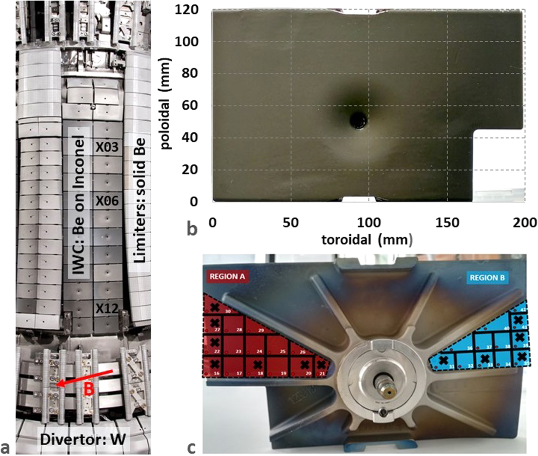
The study was conducted on four IWC tiles: the initial not exposed; one exposed to two campaigns (ILW1–2, Tile 106) and two facing the plasma during ILW1–3 (Tiles 403 and 412). Images in figures 1(a)–(c) show the inner wall structure and the appearance of both sides of the IWC tiles. The tile numbers carry on the information about the location of respective plates: the first digit denotes the octant (section in the JET vessel), while the next digits denote the tile poloidal position counting from top to the bottom of the main chamber. Tiles 106 and 403 are located close to the mid-plane, i.e. in the region of the strongest plasma contact with the inner wall guard limiters (IWGL), while for Tile 412 contact is significantly weaker [4]. Table 1 contains data on the operation time in ILW campaigns and the limiter plasma times at respective IWGL blocks located in the neighborhood of the studied IWC tiles. The integrated data are based on infrared camera images. There are no Langmuir probes in the IWC structure, while those between the limiter tiles were not operational for most of the time.

Figure 1. (a) Inner wall of JET with marked poloidal positions of IWC tiles where X is the octant number. The arrow shows the toroidal field (B) direction; (b) front side of Tile 412, exposed to ILW 1–3; (c) Back side of Tile 412 with the cutting plan and x-marked locations of the analyzed samples.
Download figure:
Standard image High-resolution imageTable 1. Operation time in ILW campaigns and limiter plasma times at respective IWGL tiles.
| Parameter | Tile 106 (ILW1–2) | Tile 403 (ILW1–3) | Tile 412 (ILW1–3) |
|---|---|---|---|
| Total operation time (h) (limiter+divertor) | 40.19 | 62.52 | 62.52 |
| Total Limiter plasma (h) | 14.81 | 19.67 | 19.67 |
| Neighboring IWGL tile number | 9 | 12–13 | 1–2 |
| Plasma time at IWGL (h) | 1.32 | 3.88 a | 0.05 a |
a Mean plasma time on respective pairs of IGWL tiles estimated from data in [4]. Values obtained as a half of the sum for two limiter tiles adjacent to a respective IWC tile.
The size (up to 120×192 mm) and weight (around 1.8 kg) of the Be-coated and tritium-contaminated tiles make the ex situ examination difficult. Only a limited number of analyses could be done for the whole tiles. Therefore, special procedures had to be developed to section ILW bulk metal tiles (Be, W, Inconel) by sawing, while observing all safety measures in handling contaminated materials, with a simultaneous temperature control (below 60 °C) to prevent fuel release. The cutting plan with a map of samples, figure 1(c), proves that detailed study was done on specimens from different toroidal positions. Region A is located next to the protruding limiter and, therefore, it is partly shadowed from the plasma, while Region B is adjacent to the next column of the IWC tiles, i.e. close to the center of the cladding.
Full (i.e. not cut) Tiles 106, 403 and 412 were first examined at the Technical University of Lisbon by means of backscattered ions and Nuclear Reaction Analysis (NRA). Backscattered primary ions give information about the sample composition by measuring their energy after elastic collision with the sample and NRA by measuring the nuclear reaction products of known reactions. For those measurements 2.3 MeV H+ and 3He+ beams were used, respectively, with detectors at 135° and 150° to the incoming beam direction. Measurements were made in toroidal and poloidal directions to determine possible variations in the D content and Be layer thickness. The data were analyzed with IBA DataFurnace NDF v9.6a [13].
Subsequently, the not exposed and two exposed plates (Tiles 106 and 412) were cut at the Institute of Atomic Physics, Bucharest, Romania. These samples were mainly 1×1 cm squares, but a few triangular plates were also produced; an example of the cutting map is shown in figure 1(c). Three cut samples of the unexposed plate, nine of Tile 106 and twelve of Tile 412 were available for analysis at the Tandem Accelerator Laboratory of the Uppsala University by means of NRA and time-of-flight heavy ion elastic recoil detection analysis (ToF-HIERDA). In ToF-HIERDA, surface atoms are released in forward direction by elastic collisions with the heavy energetic ion beam. The flight time and energy of the recoils are measured. This allows the determination of quantitative depth profiles (up to several hundreds of nm) of respective species [14].
NRA was performed with a 4.5 MeV 3He2+ beam. The most relevant reaction are D(3He,p)4He, 9Be(3He,α)8Be and 9Be(3He ,pi)11B with a detector situated at 170° with respect to the incoming ion beam. The results were analyzed with SIMNRA [15]. A complete depth profile for the full depth of the layer cannot be achieved for all elements and consequently the stopping factors needed for NRA have an uncertainty of 10%–20%. An additional error can be the limited availability of cross section data at higher energies. Available cross section data commonly have an error of 1%–2%, sometimes up to 10% [16, 17].
ToF-HIERDA was performed with an iodine (127In+, n = 8 or 10) beam at energy of either 36 MeV or 44 MeV. A combined time-of-flight detector system with a segmented gas ionization chamber was used [14] to determine the content and depth profiles of impurity species in the initial and plasma-exposed Be layers. The spectra were analyzed with the Potku software [18]. ToF-HIERDA is the only technique capable of detection and quantitative depth profiling with particularly high mass resolution for low-Z isotopes in the atomic mass range 1–20. However, surface roughness is a big source of uncertainties, while Be coatings are rough as can be seen in [8] and in section 3.3. In total the uncertainty for ToF-HIERDA ranges up to 30% for depth scale and integration over areal densities when all possible error sources of the experiment are summed up [14].
The changes in surface morphology of the Be layers were determined with scanning electron microscopy (SEM) using Zeiss LEO1530 equipped a Be-sensitive Oxford AZtec energy dispersive X-ray spectrometer (EDX); AZtec software, version 5.0 SP1.
3. Results and discussion
3.1. Total Deuterium content and Beryllium layer thickness
Table 2 presents the Be and D contents measured on a number of samples sectioned from the unexposed and two plasma-exposed tiles. Figures 2(a) and (b) show the toroidal profiles of Be and D, respectively, measured on the whole (not cut) exposed tiles. The Be layer thickness is given for an assumed material density of 1.85 g/ cm 3. However, with the increasing content of co-deposited elements the material density increases and the actual layer thickness after exposure could be different than listed in table 2 and figure 2(a). We emphasize that data from the tile central area, i.e. the funnel-shaped dip (toroidal position 82–118 mm) near the bolting hole, will not be discussed in the following. Any attempt of interpretation may be strongly misleading because of possible non-uniformity of the original coating in that region and analytical difficulties related to the change of beam-target geometry when measurements are done on inclined surfaces.
Table 2. Summarized NRA results for the unexposed and exposed tiles measured with a 4.5 MeV 3He2+ beam. The Be layer thickness is given for an assumed material density of 
| Tile | Region | Be [ ] ] | Be [ ] ] | D [ ] ] |
|---|---|---|---|---|
| Unexposed | average | 110–115 | 9.0 | — |
| 106 | A | 94–96 | 7.6–7.8 | 210–335 |
| B | 98–120 | 7.9–9.7 | 120–150 | |
| average | 102 | 8.4 | 199 | |
| 412 | A | 125–130 | 10.1–10.5 | 505–605 |
| B | 136–149 | 11.0–12.0 | 303–452 | |
| average | 134 | 10.8 | 481 |

Figure 2. Toroidal profiles of (a) beryllium layer thickness and (b) deuterium retention on the IWC tiles, measured with a 2.3 MeV 3He+ and H+ beam. The Be layer thickness is given for an assumed material density of 
Download figure:
Standard image High-resolution imageThe analyses done for three samples located a few cm apart on the not exposed tile have revealed high uniformity of the initial Be layer thickness (9.0 μm). The Be thickness on the two exposed plates (data in table 2) is different: around 8.5 μm and 11.0 μm on samples from Tiles 106 and 412, respectively. On a given tile, the thickness varies approximately within ±1.3 μm (10%–16%). The same range of quantitative variations on those two plates are seen on the entire toroidal scans, figure 2(a), while much more pronounced differences are on Tile 403 from 7 μm near the center of the IWC column to 12 μm in the limiter shadow. It is difficult to state whether the increased Be content in the limiter shadow on 403 is related to the deposition by material eroded from another area of the IWC coating or from the adjacent or even from more distant overheated limiters, i.e. upper dump plates (UPD). The first two options are equally probable, while the latter hypothesis is least plausible, because the strongest erosion of UPD occurred at the end of ILW-2 [19]. Therefore, one would have expected a similar or even stronger effect on Tile 106 retrieved after ILW-2.
In summary, all observed variations in the Be layer thickness clearly indicate local material erosion and deposition. The results also provide crucial information that in neither case the coating thickness has dropped below 7 μm, i.e. below the value specified as the minimum initial thickness. However, the exact erosion-deposition balance of Be cannot be determined because the layer thickness on respective tiles was not measured before their installation in JET. At that time, there were technical limitations for the pre-characterization of those large and heavy tiles. The research and development (R&D) process performed on several witness samples (e.g. 2×12 cm Inconel stripes) located next to the coated tiles had shown high uniformity of the initial Be layers. This fact has been confirmed recently when analyzing samples cut from the initial tile. Secondly, the decisions on the retrieval of IWC plates became viable once spare tiles could have been manufactured. For that reason, it is not intended to judge whether the results for actual IWC components are in agreement with the data for wall inserts. These were Inconel 600 buttons (10 mm in diameter) having one half coated with nominally 40 nm thick W film obtained by physical vapor deposition and the other half with 2.5–3.0 μm thick Be layer obtained by TVA. The erosion from these pre-characterized Be marker coatings had been reported at the level of 0.7–0.9 μm (the sum for three campaigns) with erosion rates dependent on the insert location [11]. Taking into account the variations in the Be thickness (±1.3 μm) on the exposed IWC, it would be difficult to draw conclusions about erosion at the level below 1 μm. However, It should be added that the production methods of Be layers on IWC [8] and those on wall inserts [12] were not alike thus resulting in significant structural differences.
Data in table 2 and figure 2(b) provide insight into the amount and toroidal distribution of deuterium on the tiles. The most important is that the retention on most of the studied areas does not exceed 1×10¹⁸ D cm−2. This is highly consistent with D contents measured on deposition areas of IWGL [4]. Such retention level is considered as low, especially when compared to the inventory in JET with carbon wall (JET-C) where over two orders of magnitude greater values were measured [20]. Besides that similarity, some other features are perceived. The overall deposition patterns on Tiles 106 and 412 are rather uniform despite some toroidal variations. The absolute D contents are different: 0.1–0.4×1018 cm−2 and 0.3–1.1×1018 cm−2 on 106 and 412, respectively. It is predominantly attributed to the ILW-2 finish with around 300 discharges fueled with H2 thus leading to in situ H-D isotope exchange. Two other aspects, the differences in the total exposure time and the plasma contact time with IWGL blocks adjacent to respective IWC, may be consequently considered less important (data in table 1).
Another point is in the comparison of the D retention data for the whole (not cut), figure 2, and cut tiles, table 2. While the Be thickness results for Tile 106 and 412 agree fairly well in both cases, the deuterium data are different by a factor of around two. The average amount of D on the not cut Tile 106 is 0.32×1018 cm−2, which is 50% higher compared to the data in table 2 for the cut samples. In the case of Tile 412 the D content is nearly twice greater on the not cut plate. No comparison is available for Tile 403 with the greatest D content because there were no second round measurements. The most probable reason for the diverging D content may be either the release of D from the layer or the isotope D-H exchange during the long time (around 2 years) separating the measurements. While the temporal decrease of D content in C-based tokamak co-deposits was studied, up to 30% in 4–5 years [21], nothing is known yet about the long-term behavior of fuel in Be-rich co-deposits or coatings from JET-ILW.
The greatest retention is on Tile 403, where the average D amount is 1.97×1018 cm−2 and the highest values in the limiter-shadowed region (approximately on 30% of the tile area) reach up to 5.82×1018 cm−2, i.e. at the same level as D inventory in the upper part of the inner divertor [5]. When compared to the adjacent IWGL tile, the highest D retention recorded in the deposition zone of the limiter was 1.4×1018 cm−2 [4], hence significantly below the amounts measured in the limiter-shadowed area of Tile 403.
Taking into account available data and the ILW operation history, a tentative attempt is made to extrapolate to the D retention in the entire Be-coated area after ILW1–3. Results for Tile 106 are excluded because of the H operation at the end of ILW-2 campaign. In the first approximation data from Regions B (not shadowed areas) on Tiles 403 and 412 are taken into account. With the average D content of 1.0×10¹⁸ atoms cm−2 the D retention limit is assessed at the level of 5.3×10²² D atoms equal to 176 mg of deuterium in the IWC beryllium coating. This value is very close to the sum of D atoms on IWGL and OPL (4.4×10²²), as extrapolated after ILW1–3 [4] and, it is five times smaller than that determined for the divertor: 25×1022 D atoms [10]. The retention of 176 mg D in the Be coating is considered as a lower limit, because there are areas with several times greater fuel content (5.8×1018 cm−2) than the mean value. For comparison, the maximum D contents in in JET-ILW, up to 12×1018 cm−2, have been detected in the inner divertor on the High Field Gap Closure Tile (Tile 0) and the apron of Tile 1.
3.2. Surface composition: hydrogen isotopes and impurities
The 3He backscattered data gathered during measurements of the total D and Be contents have indicated the presence of impurity species: C, O, Ni, W. With ToF-HIERDA the composition of the surface region was determined up to the depth of 1 μm. Particular emphasis was on low-Z species such as hydrogen isotopes, C, N, O. This also included the search for 15N and 18O used in JET as tracers. Data for Ni (Inconel) and W are presented, while the content of aluminum (Al) is not shown, because that element was most probably transferred to the coating by operation of the remotely handled equipment used during shutdowns. The average amounts of hydrogen isotopes and impurity atoms in Regions A and B on each tile are collected in table 3. The atomic concentrations are shown for two depths, 1500 and 9000×1015 atoms cm−2, to discriminate between the surface/near-surface layer and the bulk of the coating. Detailed depth profiles of several species identified in Region A are displayed in figure 3. Impurities with very small concentrations (<0.1 at.%) are left out of the plot for clarity.
Table 3. Collected ToF-HIERDA results for hydrogen isotopes and plasma impurity species on the initial and exposed tiles. Results are given for 1500 and 9000 at. cm−2, respectively.
Atomic concentrations [ ] ] | |||||||||||
|---|---|---|---|---|---|---|---|---|---|---|---|
| Tile | Region | Depth | Be | O | 2D | 1H | C | N | Ni | W | |
[ at.cm−2] at.cm−2] | [nm] | ||||||||||
| unexposed | — | 1500 | 135 | 1473 | 66 | — | 11 | 16 | — | 13 | — |
| 9000 | 785 | 8669 | 245 | — | 46 | 68 | 2 | 30 | — | ||
| 106 | A | 1500 | 175 | 1092 | 325 | 10 | 79 | 40 | 27 | 11 | 1.1 |
| 9000 | 945 | 7414 | 1120 | 68 | 177 | 156 | 81 | 50 | 3.0 | ||
| B | 1500 | 165 | 1199 | 249 | — | 82 | 24 | 25 | 7 | 1.0 | |
| 9000 | 905 | 7753 | 913 | 44 | 160 | 110 | 63 | 37 | 2.6 | ||
| 412 | A | 1500 | 185 | 1019 | 410 | 38 | 14 | 36 | 27 | 39 | 2.3 |
| 9000 | 1025 | 6725 | 1835 | 119 | 50 | 123 | 61 | 116 | 6.0 | ||
| B | 1500 | 165 | 1230 | 285 | 24 | 7 | 14 | 14 | 10 | 0.8 | |
| 9000 | 915 | 7800 | 1044 | 88 | 24 | 52 | 32 | 31 | 1.7 | ||

Figure 3. Depth profiles in atomic % to a depth of 9000×1015 atoms cm−2 plotted logarithmically. Depth profiles of the unexposed, Tile 106 Region A and Tile 412 Region A samples.
Download figure:
Standard image High-resolution imageAs expected, oxygen is the major alien species, but its content—especially in the surface region—has increased by nearly one order of magnitude after plasma exposure. It informs about: (i) the low oxygen contamination of the initial coating (5 atomic % at the very surface down to 1.5–2 at.% in the bulk) and (ii) efficient gettering of O plasma impurities. In general, the distribution of impurities, both depth and lateral, is not uniform. The results in table 3 prove greater impurity contents in Regions A than in B on the two exposed tiles. The impurity accumulation in Region A on Tile 106 is up to 7 at.% greater than on Region B, while for Tile 412 the difference amounts to nearly 13 at.%. With the information that Region A is adjacent to the protruding limiters, the increased impurity deposition may be explained by the fact that the IWGL tiles partly shadow Region A from plasma impact; the magnetic field direction is marked in figure 1(a). This leads to a lower erosion of the IWC surfaces and, simultaneously, to a higher net impurity deposition.
Data in table 3 and depth profiles in figure 3 show that the impurity content in the surface and near surface layer (1500×1015 atoms) is relatively higher than if the entire analyzed depth of 9000×1015 atoms is considered. The amount of impurities clearly decreases with depth. This applies to all detected impurities on the initial and exposed tiles. The long-term diffusion of impurities into the porous coating cannot be excluded, but it should be considered that ToF-HIERDA provides results only for the very surface layer, less than 1 μm. The atomic content of impurity species constitute around 28 at.% (106) and 29 at.% (412) of the surface layer composition. Averaged contents of H, D, Be, C, N, O and Inconel for the depth of 1500×1015 at.cm−2 plotted logarithmically for vividness are in figure 4. In bar charts for the exposed tiles, the orange-hatched part corresponds to the impurity content in the initial sample. The total height of respective bars is the total content of the element in the surface. No distinction is done for Be, as it is the main element.

Figure 4. Average composition in atomic % to a depth of 1500×1015 atoms cm−2 for the unexposed and exposed Tiles 106 and 412. The figures are plotted logarithmically. For the second and third figure, the orange-hatched part of the bar is the impurity content of the initial sample. The total height, blue and orange colored bar, is the total content of the element in the tile. For beryllium no subtraction is done, as it is the main element.
Download figure:
Standard image High-resolution imageThe results prove high purity of the initial Be coatings in which the C content barely exceeds 1at.%. On the exposed tiles, the amount of respective plasma impurities (other than oxygen) stays below 2 at.%. Small amounts of W were detected (≤0.14 at.%). The exposed layers retain nitrogen. It is a general feature of all ILW plasma-facing surfaces with co-deposits; once again, a long-term N retention in the torus is demonstrated. The presence of the 15N tracer puffed from the divertor at the end of ILW-3 has also been identified on Tile 412, but the amount is at the detection limit of 5×1014 cm−2.
At last, results for hydrogen and deuterium are discussed. The initial H content was 0.8 at.% and the increase could have been expected due to the D-H isotope exchange in the co-deposited layer when the tiles after ILW campaigns are stored for years in ambient atmosphere. Such expectations are not supported by either result because: (a) the amount of H detected on Tile 412 is equal to that on the initial tile surfaces; (b) relatively high H content on Tile 106 derives from the ILW-2 finish with around 300 discharges with H2 fueling and - as discussed earlier - the exchange occurred already during the plasma impact. As a result, the surface layer of Tile 106 contains only 1×10¹⁶ D cm−2 in the limiter-shadowed Region A, while in Region B no species could be identified with the D detection limit at 5×10¹⁴ atoms cm−2. In summary, the retention results obtained by NRA and ToF-HIERDA are qualitatively fully coherent showing significantly less D on Tile 106 than on 412. The D amounts and depth profiles determined by ToF-HIERDA clearly indicate the presence of fuel at a greater depth than accessible by that method. For obvious reasons, the total retention data are those measured by NRA and discussed in section 3.1.
3.3. Surface micro-structure and composition
High-resolution SEM images in figures 5(a)–(c) show respectively the initial appearance of the Be coating on Inconel and then after high-heat flux testing at 1.8 MW m−2 and 2.55 MW m−2 during the R&D process [8]. The initial platelets structure is maintained nearly intact under the 1.8 MW m−2 load, but the structural changes start occurring under the exposure at the load of 2.55 MW m−2.

Figure 5. SEM images of Be coatings: (a) initial; (b) tested up to  (c) tested up to
  Reproduced courtesy of IAEA. Figure from [8]. Copyright (2007) IAEA.
Download figure:
Standard image High-resolution imageSurface topography of the initial and exposed Tiles 106 and 412 is shown in figures 6(a)–(c). The clear platelets visible of the unexposed surface, similar to that in figures 5(a)–(b), became blurred after exposure to ILW1–2 and then characteristic features of single Be flakes nearly disappeared in the course of further exposure to plasma. One may assume the changes occurred by co-deposition of different species, oxygen gettering and long-term impact of charge exchange neutrals. Surface melting by excessive heat loads may also be considered, though there is no clear record on disruptions hitting the lower part of the limiter column. Two features may be perceived on the exposed surfaces: (i) the appearance of granular structures; (ii) rounded rims of the flakes (white in secondary electron images) indicating the decrease of electrical conductivity and, by this, suggesting the change of chemical composition, i.e. formation of a semi-conductive or insulating phase. The granular structures, 10 nm to 40 nm in diameter, occupy the whole sample surface, as illustrated by high magnification images in figure 7. These structures cover samples from Tile 106 and Tile 412, whereas the unexposed samples are mostly clean.

Figure 6. Surface features of the: (a) unexposed tile; (b) Tile 106 exposed to ILW1–2 and (c) Tile 412 facing the plasma during ILW1–3.
Download figure:
Standard image High-resolution image
Figure 7. High-resolution SEM images of granular structures on Tile 106.
Download figure:
Standard image High-resolution imageBesides the bright-looking rims and granular structures also some winding tube-like objects were observed. They appear in figure 7(a), while a clear evidence is presented in figure 8 (a)–(b) which show both a detaching rim and an isolated tube. EDX spectra recoded on the coating and on the tube are compared in figure 8(c) where K-alpha lines of Be and O are marked. The Be:O concentration ratios calculated with the AZtec software amount to 9.1 and 5.3 for Spectrum 1 and Spectrum 2, respectively. It proves the increased oxygen content in the tube in comparison to the coating surface. It also indicates the formation of Be-O compound, though the exact stoichiometry of the whole tube-like structure cannot be determined from the EDX data. In summary, SEM and EDX document the erosion of Be layers caused by the formation and spalling-off of oxide structures on the edges of the layers.

Figure 8. Tube-like structure and EDX spectra on a sample from Tile 412; (a) a tube-like structure detaching from the tile surface; (b) a single tube with marked areas of EDX analysis; (c) comparison of EDX spectra recorded at the two positions marked in frame (b).
Download figure:
Standard image High-resolution image
4. Concluding remarks
The first-ever examination of the Be-coated IWC tiles have brought information on fuel retention and on the Be coating modification by plasma impact. The main objective, strongly motivated by the planned D-T campaigns [9, 10], was to determine the fuel content and its share in the entire inventory in JET. With the averaged data of 1.0×10¹⁸ D cm−2, the total D retention amounts to 5.3×10²² D atoms (176 mg) in the entire IWC beryllium coating for ILW 1–3. This value is equal to the sum of D atoms on IWGL and OPL, as assessed after ILW1–3 [4] and it is five times smaller than determined for the divertor: 25×1022 D atoms [10]. The retention in IWC would correspond to 130 mg T in the case of equimolar D-T operation. Those numbers are considered as a lower retention limit, because there are areas with several times greater fuel content (5.8×1018 cm−2) than the mean value. However, it is not possible to state on what fraction of the IWC area the D content reaches that high value, i.e. whether it is local or repeated in ten toroidal positions. It has also been shown that the operation with H2 fueling efficiently reduces the amount of heavier hydrogen isotopes in the surface layer up to several hundreds of nm. In conclusion, one tentatively states that the IWC coating is not a major place of fuel accumulation in JET-ILW. However, its contribution to the entire fuel inventory and balance (42×1022 D atoms [10]) would be on the level of approximately 13% and, therefore, cannot be neglected.
The Be layer thickness on the exposed tiles is not uniform, but in neither place it is less than 7 μm thick. There are also no signs of complete erosion. This proves good long-term adherence to the Inconel substrate. No material mixing with the substrate components has been identified. Nickel, the main constituent of Inconel, is detected only as a co-deposited species in the surface layer of the Be coating. Its appearance is mainly related to the co-deposition of Ni originally eroded from the JET vacuum vessel (not protected parts of the Inconel wall) and grills of ICRF antennas. The microscopy and ion beam data presented above strongly indicate that the IWC itself is not a major source of Ni plasma impurities.
Microscopy has allowed for the observation of progressive changes in the surface structure of the layers. One pathway of the coating erosion occurs via the formation of oxygen-rich (probably BeO) tube-like structures on the edges of Be flakes. Eventually the material from the edges spalls-off in the form of small debris approximately 2–3 μm long and 0.3–0.4 μm in diameter. It happens most probably due to thermo-mechanical incompatibility between Be and those oxygen-rich forms. This type of beryllium erosion has not been reported earlier. It may be tentatively stated that a side result of this work is probably the first-ever documentation on how the Be surface in a tokamak is modified and partly eroded by oxygen gettering. At this point, however, it is difficult to say whether the same mechanism would apply either to solid Be wall tiles or to Be-rich co-deposits on PFC and what would be the impact on the stability of co-deposited layers. This topic certainly is worth attention in future studies.
Acknowledgments
This work was carried out within the framework of the EUROfusion consortium and has received funding from the Euratom research and training programme 2014–2018 and 2019–2020 under Grant Agreement No. 633053. The views and opinions expressed herein do not necessarily reflect those of the European Commission. The work has been supported by the Swedish Research Council (VR), Grant 2015–04844. Financial support of the Tandem Accelerator Infrastructure by VR-RFI (contract #2017–00646_9) as well as the Swedish Foundation for Strategic Research (SSF) under contract RIF14–0053 is gratefully acknowledged.
Data availability statement
The data that support the findings of this study are available upon reasonable request from the authors.