Abstract
In this paper, the Haar wavelet discretization method (HWDM) is proposed for the calculation of natural frequency of the laminated composite conical-cylindrical coupled shells. The displacement components of the system are set by the first order shear deformation shell theory (FSDST), and all the displacement functions of conical and cylindrical shells including boundary conditions are obtained by the Haar wavelet and its integrals. The Hamilton's principle is applied to the constitution equation and the artificial spring technique is introduced to generalize the boundary and continuity conditions of the coupled structure. The convergence and accuracy of the proposed method are validated by comparing with the results obtained from the previous works and finite element analysis, and the proposed method shows high accuracy, reliability and good convergence in both individual structure and coupled structure. Using the proposed method, in the laminated composite conical–cylindrical coupled shell with any boundary condition, new numerical results on the natural frequency are obtained along with the parameter studies, and these results can provide the referential data for the following research in this field.
Export citation and abstract BibTeX RIS
1. Introduction
The laminated composite rotating shell is widely used in many engineering fields such as aerospace, marine and building engineering due to the excellent dynamic characteristics and special self-laminated structural properties. Since the 50 s of last century, many researches on the vibration analysis of shell structures have been conducted widely, and with the invention of composite materials, the rotating shells composed of composite materials have been extensively studied.
By applying the classical shell theory (CST) [1–5], first-order shear deformation shell theory (FSDST) [6–9], higher-order shear deformation shell theory (HSDST) [10–14] and so on, the simple types of rotating shells such as cylindrical, conical and spherical shells were widely studied.
However, the conical-cylindrical coupled shell structure is widely used in the real engineering such as aerospace, marine and chemical industry and building engineering and these constructions are affected by vibration during the operation. Therefore, when these structures are used in the engineering field such as aerospace and marine industry, the construction can be destroyed. On the other hand, when they are used as containers of high-speed rotating machines such as separator, it can cause the destruction and vibration noise even during the normal operation. Therefore, it is very important to understand the vibration characteristics of conical-cylindrical shells.
For the recent 10 years, the researches on the coupled shell structures which have been of interest in the real engineering applications have been extensively conducted, and the new analytical methods and research results were published in many previous references.
Kalnins [15] and Rose et al [16] investigated the rotating symmetric shell using the classic bending theory. Hu and Raney [17] suggested the multi-segmental numerical integration technique to obtain the analytical results of cylindrical-conical coupled shell and proved the accuracy of the proposed method through the experiments. Irie et al [18] used the transfer matrix method to study the vibration behavior of cylindrical-conical coupled shell. Benjeddou [19] proposed the local-global B-spline finite element method and applied it to the modal analysis of the coupled rotating shell structure. Caresta and Kessissoglou [20] used the classical approach to study the vibration characteristics of the coupled cylindrical-conical shell made up of isotropic materials. In their study, the wave solution was adopted for solving the cylindrical shell equation, and the conical shell equation was solved using the power series solution. Then, these two solutions are coupled under the continuity condition at the junction. EI Damatty et al [21] conducted the numerical analysis on the dynamic behavior of the coupled cylindrical-conical shell using three-dimensional finite element method. Qu et al [22–26] proposed a modified variational approach and analyzed the free and forced vibrations of the ring-stiffened conical—cylindrical coupled shell, cylindrical-conical-spherical coupled shell and spherical-cylindrical-spherical coupled shell. Using the modified Fourier–Ritz method, Ma et al [27, 28] studied the free and forced vibrations of coupled conical—cylindrical shell made up of isotropic materials with general boundary conditions. Based on the Rayleigh–Ritz method and classical thin shell theory, Lee et al [29, 30] analyzed the free and forced vibrations of coupled spherical—cylindrical shell with classical boundary conditions such as clamped, simply-supported and free boundaries and proved the accuracy of results experimentally.
H Bagheri et al [31] studied the free vibration characteristics of middle-supported conical shell with isotropic homogeneous material using the generalised differential quadrature (GDQ) method. In addition, using the same method, the free vibration analysis of not only the conical-cylindrical-conical coupled shell[32] and conical-conical coupled shell [33] with isotropic homogeneous material but also the joined cylindrical–hemispherical shells [34] with the functionally graded material are conducted.
Su et al [35] proposed the Fourier Spectrum Element Method (FSEM) to study the vibration analysis of conical—cylindrical-spherical coupled shell with general boundary conditions and Cheng et al [36] analyzed the vibration characteristics of conical—cylindrical coupled shell by applying the variation method. Wang et al [37, 38] suggested the Jacobi-Ritz method for the first time, analyzed the characteristics of free vibrations of the isotropic and laminated composite coupled doubly-curved revolution shell structures and proposed new numerical results. The research on the vibration analysis of various kinds of combinational shells can be found in the following references [25, 39, 40]. In addition, a lots of researchers proposed the discrete singular convolution method [5, 6, 41], a general domain decomposition method [7, 25, 42], meshless method [43–46], spline method [8, 47] and boundary element method [48] for the vibration analysis of the rotating shell.
From the considerations of the previous works, most of the coupled structures considered until now are made of isotropic materials and few publications on the laminated composite materials were reported. Also, a variety of analytical and calculation methods for the calculation of natural frequency of the coupled shell structure are considered as neglectful, and it is still necessary and very important to develop simple and efficient numerical method for vibration analysis of this kind of combinational structure. Wavelet method has a good prospect in the mathematical field and has been developing rapidly. In recent years, many new and effective numerical methods based on the wavelet method have been developed as a powerful tool for mathematical analysis and engineering calculation [49–55].
Especially, the Haar wavelet method has drawn considerable attention as mathematical simplicity and the solution methods of integral and differential equations based on the Haar wavelet were considered in many papers [56–65]. Since the solution procedure is simple and direct, the Haar wavelet has been proven to be an effective tool for solving various problems, such as differential and integral equations [60, 62], Poisson equations and biharmonic equations [63], eigenvalues of regular Sturm–Liouville problems [64] and high order differential equations [65]and damage evaluation of plates [66]. Xie et al [67–69] applied the HWDM to the free vibration analysis of the isotropic cylindrical shell, laminated composite conical and cylindrical shell and obtained the accurate solution.
Nowadays, with the development of science and manufacturing technology, not only the laminated composite materials but also other composite materials including founctionally graded material(FGM), founctionally graded porous material(FGPM), founctionally graded carbon nanotube reinforced composite(FG-CNTRC) and Graphene reinforced composites(GRC) are widely applied. The content on the vibration analysis of FG beam, FG plate and FG shells using the Haar wavelet can be found in the references [70–74]. Through the analysis of these references [70–74], it can be seen that the Haar wavelet method is applied effectively not only for the structure of laminated composite material but also for the vibration characteristics research of FGM structure and other composite material structures. The research on the analysis of micro or nano structures made up with various types of composite materials can be found in the references [75, 76]. M Kirs et al [77] conducted the vibration analysis of nanobeams using the Haar wavelet method, and this research showed that the Haar wavelet method can be applied to the vibration analysis of nano scaled structures.
However, it appears that the Haar wavelet method has not been used for the analysis of free vibration of coupled shell structure. Therefore, the main purpose of this research is to introduce the Haar wavelet discretization method to the calculation of natural frequency of laminated composite conical-cylindrical coupled shell with elastic boundary condition. As mentioned in reference [7], in the higher-order shear deformation theory, comparing with first-order shear deformation theory, the calculation requirement is high, have some boundary items difficult to apply and complex forms of formula should be introduced. Therefore, in this research, the FSDT is introduced as a theoretical model for the analysis of free vibration of laminated composite conical-cylindrical coupled shell. All displacements and its differentiations in the motion equation are expressed by the Haar wavelet and its differentiation along the axis direction and by the Fourier series along the circumferential direction. The integral constant is determined by the boundary condition. Many numerical examples for the validity of the accuracy and versatility of the proposed methods are performed by the analysis of parameters.
2. Theoretical formulations
2.1. Geometric relationship
The laminated structure was shown in many previous works; therefore, there is no need of further explanation here. The geometric and coordinate systems of laminated composite conical-cylindrical coupled shell are described in figure 1.

Figure 1. Co-ordinate systems of the laminated composite conical–cylindrical coupled shell.
Download figure:
Standard image High-resolution imageThe conical shell is composed of the (xc
, θc
, rc
) coordinate system. Here, xc
is the coordinate along the generator of the cone starting at its small edge, θc
is the circumferential coordinate and rc
is the coordinate perpendicular to middle of the conical shell. The displacements of the conical shell with respect to this coordinate system are expressed by uc
, vc
and wc
in the xc
, θc
and rc
directions respectively. φ is the semi-vertex angle of the cone, R1 and R2 are the radii of the cone at its small and large edges respectively, Lc
is the cone length along its generator and h.c.
is the uniform thickness of the conical shell. The radius of the cone at any point along its length is defined as  The cylindrical coordinate system (xl
, θl
, rl
) is used for the cylindrical shell, where xl
, θl
and rl
represent the axial, circumferential and radial directions respectively. The ul
, vl
and wl
represent the deformations of the cylindrical shell in the xl
, θl
, and rl
directions respectively. In both the conical and cylindrical shells, thickness is supposed to be negligible comparing to length or radii of curvature of the shell and the normal to the middle surface is assumed to be always straight and vertical to the middle surface. Here, the subscripts c and l represent the conical and cylindrical shells respectively. The both ends of coupled structure are supported with artificial boundary springs at along the five displacement directions, and the boundary condition can be generalized according to the stiffness of boundary springs. In the similar way, the continuity condition can be generalized by setting the artificial connective spring at the connected part of the conical and cylindrical shells.
The cylindrical coordinate system (xl
, θl
, rl
) is used for the cylindrical shell, where xl
, θl
and rl
represent the axial, circumferential and radial directions respectively. The ul
, vl
and wl
represent the deformations of the cylindrical shell in the xl
, θl
, and rl
directions respectively. In both the conical and cylindrical shells, thickness is supposed to be negligible comparing to length or radii of curvature of the shell and the normal to the middle surface is assumed to be always straight and vertical to the middle surface. Here, the subscripts c and l represent the conical and cylindrical shells respectively. The both ends of coupled structure are supported with artificial boundary springs at along the five displacement directions, and the boundary condition can be generalized according to the stiffness of boundary springs. In the similar way, the continuity condition can be generalized by setting the artificial connective spring at the connected part of the conical and cylindrical shells.
2.2. Governing equations
According to the FSDT, the displacements at any point of the shell can be expressed by the displacement at the middle surface and the rotating component [37].

where subscript ζ = (c, l), represent the conical and cylindrical shells respectively, u, v and w indicate the displacement components in α, β and z directions, and φα and φβ are the rotations of transverse normal along the β and α axis.
The deformation at any point of shell can be defined by the strains and curvature changes at the middle surface.

where  indicate the normal and shear strains in the middle surface, kα
, kβ
, kαβ
are the curvature and twist strains, and
indicate the normal and shear strains in the middle surface, kα
, kβ
, kαβ
are the curvature and twist strains, and  are transverse shear strains[37].
The strains and curvature changes at the middle surface can be expressed as follows.
The coordinates, characteristics of the Lamé parameters and radii of curvatures are as follows;

According to the generalized Hooke's law, at the kth layer of laminated shells, corresponding stress-strain relationship can be expressed as follows;

where σα
and σβ
are normal stresses, ταβ
, ταz
and τβz
are shear stresses.  is the stiffness coefficients of laminated layers and obtained from the following equation.
where,  is the fiber direction angle and indicates the angle between the principle and radius directions of the kth layer.
  is the reduced elasticity coefficient at the kth layer and expressed as follows [37].

where G11, G13 and G23 indicate the shear moduli. E11 and E22 represent the effective Young's moduli of laminated composite shells in the principle material coordinates. μ12 and μ21 are Poisson's ratios. If the stresses are integrated with respect to shear, the force and moment results are obtained as follows.
Also, the stress-strain relationship is written in the matrix form as follows.
where, κ is the modified shear coefficient and set as 5/6 in this paper. Aij , Bij and Dij are stretching, stretching -bending and bending coefficients respectively and expressed as follows.

where, N indicates the total number of laminated layers, and the strain energy occurred by the vibration of laminated composite rotating shell is expressed as follows.
The corresponding kinetic energy function is given as follows.
In equation (12), I0, I1, I2 are the inertia item and defined as follows.
The potential energy stored in the boundary springs can be written as
where, kub , kvb , kwb , kφb and kθb are stiffness of the boundary springs at two ends of the coupled structure. The strain energy stored in the connective spring at the combined part of conical and cylindrical shells are expressed as follows.
where, kuc , kvc , kwc , kφc and kθc are stiffness of the connective springs at the combined plane of the coupled structure.
In this article, it is assumed that there exists no energy by the external force as the main purpose is to calculate the natural frequency of combinational structure.
The total Lagrangian functional (L) of the laminated composite conical-cylindrical coupled shell is written as follows.

Applying the Hamilton's principle, the constitution equation of the shell is obtained as follows.


The constitution equations of individual rotating shells are expressed in matrix form as follows.

where, the detailed expression formula of coefficients Lij , and Gij can be found in appendix A.
The boundary condition equations at two ends of the conical-cylindrical coupled shell are obtained as follows:
Also, the continuity condition equations at the combined part of conical-cylindrical coupled shell are expressed as follows.
According to the refernece [68], the displacement and rotation components in the circumferential direction can be extended into the Fourier series by applying the separation of variables.

where, ω is angular frequency and non-negative integer n is number of waves of the corresponding mode. U(α), V(α), W(α), Φ(α)and Θ(α) are unknown variable function to determine.
Substituting equations (22) into (19) and performing some algebraic operations, the construction equation can be written in following form.


where, the detailed expression formula of coefficients  can be found in appendix B.
In the similar way, the same forms of equation can be obtained with respect to boundary and continuity conditions.
For boundary conditions;
Left boundary:
Right boundary:
For continuity conditions
Conical shell:
Cylindrical shell:
2.3. Implementation of the HWDM
Haar wavelet consisting of a group of square waves has size of +1and −1 in some intervals and has zeros in elsewhere, and it is known one of the simplest compactly supported orthogonal wavelet among the wavelet families. The details of Haar wavelet series and their integrals can be found in the following references [67–69, 72–74].
Haar wavelet series are used to discretize the derivatives in entire governing equations including boundary conditions. The Haar wavelet series is defined in the interval [0, 1], therefore, to apply the HWDM, the linear transformation statute is used for the coordinate conversion from length interval [0, L] of the rectangular plate to the interval [0, 1] of the Haar wavelet series, that is,

In the HWDM, the highest order derivatives of the displacements are expressed using the Haar wavelet series and the lower order derivatives can be obtained by integrating Haar wavelet series. The highest order derivative of the displacements in the governing equations of motion and boundary condition expressions is second order, which can be obtained by means of the Haar wavelet series as follows;

where ai , bi , ci and di are unknown coefficients of the Haar wavelets. The first order derivatives of displacements are calculated by integrating equation (27) and the the displacement functions can be obtained by integrating the above result again. The first order derivatives of displacements and displacement functions are written as follows.
Equations (27) and (28) can be expressed in the discretized matrix form as follows:
where H and P 1 , P 2 are the Haar wavelet and its integrals defined as


and notations are defined as follows.
where, f , g , h , k and l indicate the integral constants, which can be obtained by applying the boundary condition. The highest order of the displacements of boundary condition equations is first order, and the first order derivatives and displacements in equation (28) are calculated when ξ = 0 and ξ = 1. The discretization of the boundary condition equation can be manipulated in the same way as that of the displacement, and it can be written in the matrix form as follows.


where
Left boundary:

Right boundary:

With respect to the continuity condition, the equations can be expressed in the similar way as the boundary condition.
Therefore, the entire systems of the laminated composite conical-cylindrical coupled shell including boundary condition are discretized using the HWDM and the entire motion equations can be expressed in the matrix form as follows.


where A d and A b represent the Haar wavelet coefficients and the integral constants, respectively, and subscripts d and b indicate the discrete equilibrium equations of motion, the boundary conditions and connecting conditions. The general discrete motion equations (Eq. (23)) are represented by Kdd , Kdb and Mdd , Mdb . In addition, the discrete boundary and connecting condition equations (Eq. (24, 25)) are represented by Kbb and Kbd . Their concrete expressions are shown in appendix C.
Since the maximal level of resolution J of Haar wavelet is set as 8, maximal dimension of Haar wavelet is 2J+1 = 512. Therefore, the matrix degrees of Kdd , Kdb , Kbb and Kbd are 2560 × 2560, 2560 × 20, 20 × 2560 and 20 × 20 respectively, that is, in equation (38), the degree of stiffness matrix is 2580 × 2580.
A b at both sides of equation (38) can be eliminated by performing some algebraic manipulations, and the standard characteristic equation is expressed as follows.

Through the further simplification of the above equation, the following matrix expressions can be obtained.

where, ![${\bf{K}}=\left[{{\bf{K}}}_{dd}-{{\bf{K}}}_{db}{{\bf{K}}}_{bd}^{-1}{{\bf{K}}}_{bb}\right]$](https://content.cld.iop.org/journals/1402-4896/96/3/035223/revision3/psabd9f7ieqn8.gif) and
and ![${\bf{M}}=\left[{{\bf{M}}}_{dd}-{{\bf{M}}}_{db}{{\bf{M}}}_{bd}^{-1}{{\bf{M}}}_{bb}\right]$](https://content.cld.iop.org/journals/1402-4896/96/3/035223/revision3/psabd9f7ieqn9.gif) are stiffness and mass matrixes of the structure, respectively and their matrix dimension are 2560 × 2560.
are stiffness and mass matrixes of the structure, respectively and their matrix dimension are 2560 × 2560.
3. Numerical results and discussions
In this section, using the proposed method, the calculation results of natural frequency of the laminated composite conical-cyclrindrical coupled shell under the various boundary conditions including classical boundary conditions are presented and the several paramaters affecting the change of natural frequency are studied. Unless otherwise stated,, in the calculation of numerical examples, the natural frequency of conical—cylindrical coupled shell is expressed with the non-dimensional frequency parameter  and the parameters of the laminated material are set as follows.
Also, the small radius (Rc ) of conical shell is 0.5 m and the large radius (Rl ) is 1 m same as cylindrical radius.
3.1. Convergence study
In the numerical calculation, the number of terms of series must be truncated at an appropriate finite number by considering the computational cost of the numerical solution. Therefore, convergence studies are needed to establish the number of terms that should be used to obtain accurate results. The convergence criterion of the present method for a three-layered, cross-ply [0°/90°/0°] laminated composite conical-cylindrical coupled shell with respect to different the maximal level of resolution J is examined in table 1.
Table 1. Convergence of frequency parameters for laminated composite conical-cylindrical coupled shell with C–C boundary condition.
| J | |||||||||
|---|---|---|---|---|---|---|---|---|---|
| Ω | 2 | 3 | 4 | 5 | 6 | 7 | 8 | 9 | 10 |
| 1 | 0.545 | 0.532 | 0.528 | 0.527 | 0.527 | 0.526 | 0.526 | 0.526 | 0.526 |
| 2 | 0.961 | 0.941 | 0.935 | 0.934 | 0.933 | 0.933 | 0.933 | 0.933 | 0.933 |
| 3 | 1.207 | 1.134 | 1.116 | 1.111 | 1.11 | 1.11 | 1.11 | 1.11 | 1.11 |
| 4 | 1.799 | 1.626 | 1.571 | 1.556 | 1.552 | 1.551 | 1.551 | 1.551 | 1.551 |
| 5 | 2.238 | 2.019 | 1.961 | 1.945 | 1.941 | 1.94 | 1.94 | 1.94 | 1.94 |
| 6 | 2.691 | 2.385 | 2.249 | 2.214 | 2.205 | 2.203 | 2.202 | 2.202 | 2.202 |
| 7 | 2.842 | 2.651 | 2.624 | 2.608 | 2.603 | 2.601 | 2.601 | 2.601 | 2.601 |
| 8 | 3.637 | 2.961 | 2.767 | 2.721 | 2.71 | 2.708 | 2.707 | 2.707 | 2.707 |
| 9 | 4.375 | 3.493 | 3.214 | 3.142 | 3.123 | 3.119 | 3.117 | 3.117 | 3.117 |
| 10 | 4.881 | 4.04 | 3.674 | 3.57 | 3.544 | 3.537 | 3.535 | 3.535 | 3.535 |
As can be seen from table 1, as J increases, the frequency paramater of the coupled structure reaches a certain value. It is obvious that as J increases, the accracy of solution increases, but the calculation time and cost also increases, and if J exceeds a certain value, the error becomes very small. Therefore, in this paper, the maximal level of resolution J of Haar wavelet is set as 8 to calculate the natural frequency of laminated composite conical—cylindrical coupled structure.
In the theoretical formula, the boundary and continuity conditions of coupled shell structure are simulated by the artificial spring technique composed of three linear springs and two rotating springs. As a result, the boundary and continuity conditions are changed according to the stiffness of springs. Therefore, it is necessary to conduct the convergence study on the stiffness of elastic springs to determine the boundary and continuity conditions. In order to observe the variation characteristics of frequency according to the stiffness of individual springs, the stiffness of the spring considered increases from 103 to 1015 and the rest four elastic springs are set as 0. Figure 2 shows the frequency variation characteristics of the laminated composite conical-cylindrical coupled shell with the increase of stiffness of the boundary elastic springs. The geometric and material parameters are same as above. As can be seen in figure 2, the frequencies are almost unchanged with the increase of stiffness of the elastic spring up to a certain value (105). However, out of this value, the frequency starts to increase rapidly and keeps level again after the stiffness reaches 1012. In order to simplify the presentation, the clamped, free, simply-supported boundary conditions are represented as C, F and S, respectively. Also, three kinds of elastic boundary conditions are selected as EI , EII and EIII. Table 2 shows the stiffness of elastic springs corresponding to individual boundary conditions.
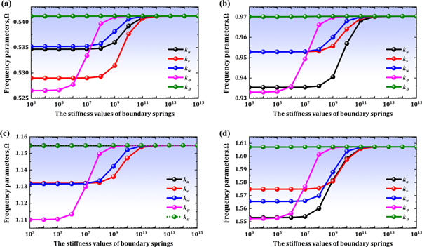
Figure 2. Convergence characteristics of frequency parameters of the laminated composite conical-cylindrical coupled shell with the increase of stiffness of the boundary springs. (a)-mode1; (b)-mode2; (c)-mode3; (d)-mode4.
Download figure:
Standard image High-resolution imageTable 2. The corresponding values of the spring stiffness for general boundary conditions.
| Corresponding spring stiffness values | ||||||
|---|---|---|---|---|---|---|
| BC | Essential conditions | ku | kv | kw | kφ | kθ |
| F | Nα = Nαβ = Qα = Mα = Mαβ = 0 | 0 | 0 | 0 | 0 | 0 |
| C | U = V = W = Φα = Φβ = 0 | 1014 | 1014 | 1014 | 1014 | 1014 |
| S | U = V = W = Mα = Mαβ = 0 | 1014 | 1014 | 1014 | 0 | 1014 |
| EI | U ≠ 0, V ≠ 0, W ≠ 0, Φα = Φβ = 0 | 108 | 108 | 108 | 1014 | 1014 |
| EII | U = V = W = 0, Φα ≠ 0, Φβ ≠ 0 | 1014 | 1014 | 1014 | 108 | 108 |
| EIII | U ≠ 0, V ≠ 0, W ≠ 0, Φα ≠ 0, Φβ ≠ 0 | 108 | 108 | 108 | 108 | 108 |
3.2. Numerical verifications
In the previous section, the characteristic parameters are determined through the convergence study for the calculation of natural frequency of laminated composite conical-cyclindrical coupled shell. Based on these results, in this section, the accuracy of the proposed method is examined by compairng with the results of prevous works and that obtaind by the fininte element method. Table 3 shows the comparison results of the frequency paramaters obtained by the proposed method with that of the prevous works in the isotropic conical-cyclindrical coupled shell. As can be seen in the table, the calculation results of isotropic conical-cylindrical coupled shell obtained by the proposed method agree well with that of previous works, which indicate that the proposed method is suitable for the analysis of free vibration analysis of the coupled structure.
Table 3. Comparison of some frequency parameters Ω for the isotropic conical-cylindrical coupled shells.
| n = 0 | n = 1 | n = 2 | |||||||
| Ω | [27] | Present | Error,% | [27] | Present | Error,% | [27] | Present | Error,% |
| 1 | 0.503792 | 0.503707 | 2E-04 | 0.292873 | 0.292864 | 3E-05 | 0.099915 | 0.099981 | 7E-04 |
| 2 | 0.609854 | 0.60985 | 6E-06 | 0.63581 | 0.635836 | 4E-05 | 0.502641 | 0.502609 | 6E-05 |
| 3 | 0.93089 | 0.930965 | 8E-05 | 0.811231 | 0.811439 | 3E-04 | 0.691144 | 0.69131 | 2E-04 |
| 4 | 0.953124 | 0.956474 | 0.004 | 0.930879 | 0.931567 | 7E-04 | 0.858632 | 0.85911 | 6E-04 |
| 5 | 0.969493 | 0.971757 | 0.002 | 0.948502 | 0.952356 | 0.004 | 0.906351 | 0.916054 | 0.011 |
| 6 | 1.009102 | 1.012376 | 0.003 | 0.991452 | 0.992376 | 9E-04 | 0.960521 | 0.960877 | 4E-04 |
| n = 3 | n = 4 | n = 5 | |||||||
| [27] | Present | Error,% | [27] | Present | Error,% | [27] | Present | Error,% | |
| 1 | 0.087584 | 0.087508 | 9E-04 | 0.144599 | 0.144439 | 0.001 | 0.199464 | 0.199375 | 4E-04 |
| 2 | 0.391539 | 0.391456 | 2E-04 | 0.330337 | 0.330175 | 5E-04 | 0.295989 | 0.295926 | 2E-04 |
| 3 | 0.514379 | 0.51441 | 6E-05 | 0.395622 | 0.395413 | 5E-04 | 0.370866 | 0.370203 | 0.002 |
| 4 | 0.750903 | 0.753383 | 0.003 | 0.644582 | 0.6465 | 0.003 | 0.57849 | 0.579258 | 0.001 |
| 5 | 0.79208 | 0.796624 | 0.006 | 0.691144 | 0.692734 | 0.002 | 0.612703 | 0.61313 | 7E-04 |
| 6 | 0.919605 | 0.919797 | 2E-04 | 0.871938 | 0.871922 | 2E-05 | 0.816743 | 0.817532 | 1E-03 |
Then, the accuray of the proposed method for the free vibration analysis of the laminated composite conical-cylindrical coupled shell is validated. However, due to the lack of the references on the laminated composite conical-cylindrical coupled shell, the accurary of the proposed method is validated by the comparison with the results from the finite element method. The software ABAQUS is used in the finite element analysis. For the finite element analysis, the element type is set as SR4 and number of element is set as 8432. The geometirc parameters are same as Tbale 1, but only the thickness(h) is set as 0.15m differently.
Table 4 shows the comparison of the first ten basic natural frequencies obtained by the proposed method with those from the finite element analysis in the laminated composite conical-cylindrical coupled shell with several boundary conditions. As can be seen in table 4, the results in two methods agrees well each other, which shows that the proposed method is very applicable not only for the isotropic material but aslo for the free vibration analysis of the laminated composite conical-cylindrical coupled shell.
Table 4. Comparison of first ten fundamental frequencies for the laminated composite conical-cylindrical coupled shells.
| C–C | F–C | C–S | S–S | |||||
|---|---|---|---|---|---|---|---|---|
| Frequency | Present | FEM | Present | FEM | Present | FEM | Present | FEM |
| 1 | 215.225 | 215.15 | 91.8724 | 91.61 | 212.849 | 212.76 | 209.865 | 209.82 |
| 2 | 235.329 | 234.83 | 201.747 | 201.89 | 230.997 | 231.29 | 230.477 | 230.91 |
| 3 | 267.985 | 268.64 | 231.078 | 231.1 | 267.985 | 268.61 | 267.985 | 268.61 |
| 4 | 374.28 | 374.43 | 233.066 | 232.7 | 374.253 | 374.4 | 370.858 | 372.88 |
| 5 | 385.291 | 384.27 | 270.649 | 270.36 | 377.048 | 377.47 | 373.039 | 376.8 |
| 6 | 425.621 | 425.87 | 340.288 | 339.73 | 422.082 | 422.29 | 417.987 | 418.25 |
| 7 | 448.064 | 448.7 | 448.052 | 448.69 | 445.524 | 446.89 | 445.523 | 446.89 |
| 8 | 512.501 | 512.09 | 455.522 | 455.8 | 500.31 | 501.41 | 491.226 | 492.32 |
| 9 | 512.993 | 512.58 | 471.932 | 470.88 | 511.376 | 511.46 | 509.438 | 509.53 |
| 10 | 543.853 | 543.34 | 543.716 | 543.22 | 532.243 | 533.67 | 532.18 | 533.63 |
3.3. Numerical examples
Based on the validity of convergence and accuracy of the proposed method, in this section, through the analysis on the several parameters influencing the natural frequency of the laminated composite conical-cylindrical coupled shell, new frequency results are proposed.
Table 5 shows the variation of frequency parameters of the laminated composite conical-cylindrical coupled shell with different thickness under several classical boundary conditions. The calculation is performed under the conditions that the fiber direction angles of the laminate material are [30°/60°/30°], the semi-vertex angle φ = 30°, Rc = 0.5 m, Rl = 1 m, Lc = 1 m, Ll = 2 m and circumferential wave numbers n = 2. Table 5 clearly shows that as the thickness of coupled structure increases, the frequency parameters also increase no matter what the boundary condition is. Also, it can be seen that if the boundary condition is changed (for example, C–F boundary and F–C boundary), the frequency is also changed.
Table 5. Frequency parameters Ω of the laminated composite conical-cylindrical coupled shells with different classic boundary conditions.
| Boundary conditions | |||||||||
|---|---|---|---|---|---|---|---|---|---|
| h | Ω | C–C | C–F | S–S | C–S | S–F | S–C | F–C | F–F |
| 0.05 | 1 | 0.789 | 0.09 | 0.77 | 0.775 | 0.089 | 0.783 | 0.262 | 0.074 |
| 2 | 1.441 | 0.912 | 1.403 | 1.427 | 0.903 | 1.416 | 0.883 | 0.231 | |
| 3 | 1.701 | 1.529 | 1.67 | 1.682 | 1.502 | 1.692 | 1.62 | 1.052 | |
| 4 | 2.021 | 1.756 | 1.964 | 1.965 | 1.751 | 2.02 | 2.013 | 1.723 | |
| 0.1 | 1 | 0.849 | 0.156 | 0.819 | 0.825 | 0.154 | 0.843 | 0.42 | 0.142 |
| 2 | 1.6 | 0.994 | 1.538 | 1.57 | 0.984 | 1.563 | 0.963 | 0.414 | |
| 3 | 1.94 | 1.692 | 1.874 | 1.898 | 1.651 | 1.92 | 1.827 | 1.146 | |
| 4 | 2.465 | 2.024 | 2.382 | 2.391 | 2.011 | 2.455 | 2.312 | 1.958 | |
| 0.15 | 1 | 0.902 | 0.22 | 0.866 | 0.872 | 0.218 | 0.896 | 0.54 | 0.205 |
| 2 | 1.709 | 1.062 | 1.647 | 1.675 | 1.053 | 1.678 | 1.052 | 0.553 | |
| 3 | 2.156 | 1.822 | 2.086 | 2.108 | 1.787 | 2.136 | 1.996 | 1.247 | |
| 4 | 2.779 | 2.28 | 2.71 | 2.722 | 2.265 | 2.767 | 2.523 | 2.164 | |
| 0.2 | 1 | 0.948 | 0.279 | 0.912 | 0.917 | 0.278 | 0.943 | 0.629 | 0.262 |
| 2 | 1.792 | 1.123 | 1.739 | 1.76 | 1.115 | 1.77 | 1.139 | 0.66 | |
| 3 | 2.319 | 1.929 | 2.262 | 2.278 | 1.904 | 2.304 | 2.123 | 1.345 | |
| 4 | 2.983 | 2.478 | 2.939 | 2.947 | 2.467 | 2.974 | 2.673 | 2.326 | |
To help readers to understand the mode shape of coupled structure, figure 3 shows the first four types of modes under the C–C and F–C boundary conditions.
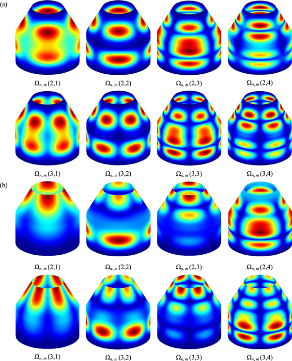
Figure 3. Mode shapes of the laminated composite conical-cylindrical coupled shells, (a): C–C, (b): F–C.
Download figure:
Standard image High-resolution imageTo consider the effect of elastic boundary conditions on the natural frequency of the conical-cylindrical coupled shell, table 6 shows the frequency parameters under the several classical-elastic and elastic-elastic boundary conditions.
Table 6. Frequency parameters Ω of the laminated composite conical-cylindrical coupled shells with different classic-elastic boundary conditions.
| Boundary conditions | ||||||||
|---|---|---|---|---|---|---|---|---|
| n | Ω | E1-C | E2-C | E1-S | E2-S | E1-E1 | E2-E2 | E3-E3 |
| 0 | 1 | 0.749 | 1.031 | 0.734 | 1.004 | 0.223 | 0.986 | 0.223 |
| 2 | 1.219 | 1.408 | 1.219 | 1.382 | 0.248 | 1.357 | 0.237 | |
| 3 | 1.252 | 1.608 | 1.227 | 1.596 | 1.042 | 1.524 | 1.042 | |
| 4 | 1.548 | 1.634 | 1.508 | 1.608 | 1.337 | 1.608 | 1.336 | |
| 1 | 1 | 0.442 | 1.085 | 0.431 | 1.065 | 0.206 | 1.051 | 0.206 |
| 2 | 1.271 | 1.577 | 1.255 | 1.564 | 0.333 | 1.535 | 0.332 | |
| 3 | 1.588 | 1.649 | 1.58 | 1.635 | 1.249 | 1.639 | 1.247 | |
| 4 | 1.663 | 1.877 | 1.643 | 1.819 | 1.541 | 1.708 | 1.54 | |
| 2 | 1 | 0.619 | 0.774 | 0.609 | 0.752 | 0.388 | 0.731 | 0.376 |
| 2 | 1.002 | 1.548 | 0.983 | 1.523 | 0.682 | 1.499 | 0.658 | |
| 3 | 1.792 | 1.909 | 1.753 | 1.885 | 1.107 | 1.852 | 1.092 | |
| 4 | 2.176 | 2.206 | 2.132 | 2.154 | 1.948 | 2.012 | 1.936 | |
| 3 | 1 | 0.763 | 0.768 | 0.746 | 0.751 | 0.627 | 0.725 | 0.612 |
| 2 | 1.301 | 1.397 | 1.289 | 1.378 | 1.039 | 1.342 | 1.01 | |
| 3 | 1.782 | 1.889 | 1.746 | 1.855 | 1.391 | 1.786 | 1.356 | |
| 4 | 2.445 | 2.536 | 2.399 | 2.479 | 1.993 | 2.298 | 1.966 | |
The laminated material is composed of four layers and the calculation is performed when fiber direction angles are [45°/−45°/45°/−45°], thickness(h) of conical and cylindrical shells are both 0.1 m and n = 0 ∼ 3. Other geometrics of coupled shell are same as table 5. Table 6 shows that the frequency is obviously different according to the change of boundary condition. Also, according to the boundary conditions, the basic frequency appears at different n values.
Next, the frequency parameters of the conical-cylindrical coupled shell according to the number of layers and forms of the laminated materials under the several classical boundary conditions and elastic boundary conditions are shown in table 7. The calculation is performed when the length (Ll ) of conical shell is 1 m, thickness of conical and cylindrical are both 0.1 m and n = 2. Table 7 shows that as the number of layer increase, the natural frequency of the laminated composite conical-cylindrical coupled shell also increases. Also, the frequency is changed in the different laminated structures even if the number of layers is same.
Table 7. Frequency parameters Ω of the cross-ply laminated composite conical-cylindrical coupled shells.
| Boundary conditions | |||||||||
|---|---|---|---|---|---|---|---|---|---|
| layer | Ω | C–C | C–F | S–S | C–S | F–C | E1-E1 | E2-E2 | E3-E3 |
| 0°/90° | 1 | 0.943 | 0.167 | 0.795 | 0.867 | 0.388 | 0.435 | 0.888 | 0.43 |
| 2 | 1.201 | 1.018 | 1.081 | 1.146 | 1.093 | 0.601 | 1.132 | 0.592 | |
| 3 | 2.176 | 1.482 | 2.127 | 2.133 | 1.634 | 1.417 | 1.985 | 1.411 | |
| 4 | 2.631 | 1.772 | 2.373 | 2.495 | 1.953 | 1.517 | 2.314 | 1.512 | |
| 0°/90°/0° | 1 | 1.146 | 0.16 | 1.013 | 1.061 | 0.35 | 0.43 | 1.02 | 0.425 |
| 2 | 1.499 | 1.168 | 1.306 | 1.401 | 1.264 | 0.621 | 1.253 | 0.608 | |
| 3 | 2.662 | 1.765 | 2.498 | 2.565 | 1.909 | 1.49 | 2.109 | 1.48 | |
| 4 | 3.404 | 2.111 | 3.252 | 3.326 | 2.414 | 1.707 | 2.634 | 1.681 | |
| 90°/0°/90° | 1 | 0.911 | 0.286 | 0.864 | 0.881 | 0.619 | 0.504 | 0.888 | 0.501 |
| 2 | 1.185 | 1.034 | 1.117 | 1.149 | 1.089 | 0.742 | 1.148 | 0.737 | |
| 3 | 2.012 | 1.469 | 1.901 | 1.934 | 1.684 | 1.396 | 1.912 | 1.394 | |
| 4 | 2.356 | 1.701 | 2.216 | 2.293 | 1.864 | 1.529 | 2.204 | 1.526 | |
| 0°/90°/90°/0° | 1 | 1.086 | 0.177 | 0.961 | 1.009 | 0.4 | 0.444 | 0.984 | 0.439 |
| 2 | 1.484 | 1.158 | 1.298 | 1.388 | 1.254 | 0.641 | 1.277 | 0.629 | |
| 3 | 2.602 | 1.76 | 2.438 | 2.506 | 1.898 | 1.5 | 2.146 | 1.49 | |
| 4 | 3.348 | 2.03 | 3.2 | 3.273 | 2.357 | 1.703 | 2.69 | 1.68 | |
| 90°/0°/0°/90° | 1 | 0.993 | 0.277 | 0.923 | 0.945 | 0.607 | 0.5 | 0.954 | 0.496 |
| 2 | 1.237 | 1.084 | 1.142 | 1.191 | 1.136 | 0.733 | 1.178 | 0.728 | |
| 3 | 2.166 | 1.519 | 2.022 | 2.065 | 1.759 | 1.421 | 1.974 | 1.417 | |
| 4 | 2.579 | 1.785 | 2.396 | 2.496 | 1.963 | 1.562 | 2.294 | 1.558 | |
Tables 8–10 shows the frequency parameters of conical-cylindrical coupled shell with different laminated structures under the classical boundary, classical-elastic boundary and elastic boundary conditions, providing researchers the reference and benchmark data on the laminated composite conical-cylindrical coupled shell. The material and geometric parameters used in this research is set as table 5. The thickness of combinational shell is set as 0.1 m in both conical and cylindrical shells.
Table 8. Fundamental frequency parameters Ω of the laminated composite conical-cylindrical coupled shells with different layer structures under classical boundary conditions.
| Boundary conditions | ||||||||||
|---|---|---|---|---|---|---|---|---|---|---|
| Layer | Ω | C–C | C–F | S–S | C–S | F–C | S–C | S–F | F–S | F–F |
| 0°/30°/60°/0° | 1 | 0.7007 | 0.1188 | 0.6509 | 0.6521 | 0.3235 | 0.6992 | 0.1159 | 0.3203 | 0.0106 |
| 2 | 0.7632 | 0.1911 | 0.7186 | 0.7188 | 0.4581 | 0.7629 | 0.1825 | 0.4526 | 0.0238 | |
| 3 | 0.7703 | 0.2676 | 0.729 | 0.7338 | 0.6554 | 0.7649 | 0.2674 | 0.6256 | 0.1058 | |
| 4 | 0.9357 | 0.4583 | 0.9136 | 0.9166 | 0.7622 | 0.928 | 0.4583 | 0.7182 | 0.2671 | |
| 5 | 0.9501 | 0.4855 | 0.9165 | 0.921 | 0.7827 | 0.9501 | 0.4855 | 0.7608 | 0.2931 | |
| 15°/30°/45°/60° | 1 | 0.6775 | 0.1518 | 0.6721 | 0.6727 | 0.3819 | 0.6769 | 0.1517 | 0.3819 | 0.0147 |
| 2 | 0.7798 | 0.1927 | 0.7699 | 0.774 | 0.4683 | 0.7755 | 0.1923 | 0.4682 | 0.1428 | |
| 3 | 0.8208 | 0.3604 | 0.818 | 0.8181 | 0.6581 | 0.8207 | 0.3604 | 0.6543 | 0.3595 | |
| 4 | 1.0581 | 0.5762 | 1.0478 | 1.0543 | 0.8193 | 1.0514 | 0.5762 | 0.8167 | 0.3687 | |
| 5 | 1.1427 | 0.6537 | 1.141 | 1.141 | 0.8867 | 1.1427 | 0.6537 | 0.8774 | 0.6535 | |
| 30°/45°/30°/60° | 1 | 0.7524 | 0.177 | 0.7438 | 0.7444 | 0.4368 | 0.7518 | 0.1765 | 0.4358 | 0.0167 |
| 2 | 0.8225 | 0.1922 | 0.8092 | 0.8131 | 0.4555 | 0.8184 | 0.1894 | 0.4536 | 0.0386 | |
| 3 | 0.9589 | 0.4245 | 0.9546 | 0.9546 | 0.724 | 0.9589 | 0.4245 | 0.7176 | 0.165 | |
| 4 | 1.1073 | 0.612 | 1.0956 | 1.101 | 0.9538 | 1.1017 | 0.612 | 0.9418 | 0.4228 | |
| 5 | 1.3506 | 0.6599 | 1.3484 | 1.3484 | 0.9558 | 1.3506 | 0.6582 | 0.9516 | 0.4261 | |
Table 9. Fundamental frequency parameters Ω of the laminated composite conical-cylindrical coupled shells with different layer structures under classic-elastic boundary conditions.
| Boundary conditions | ||||||||||
|---|---|---|---|---|---|---|---|---|---|---|
| Layer | Ω | E1-C | E2-C | E3-C | E1-S | E2-S | C-E1 | C-E2 | F-E1 | F-E2 |
| 0°/30°/60°/0° | 1 | 0.5006 | 0.7002 | 0.5005 | 0.4949 | 0.6517 | 0.3356 | 0.6851 | 0.0832 | 0.3225 |
| 2 | 0.527 | 0.7631 | 0.5165 | 0.5198 | 0.7187 | 0.3588 | 0.7488 | 0.1836 | 0.4562 | |
| 3 | 0.6919 | 0.7683 | 0.6907 | 0.6461 | 0.732 | 0.4763 | 0.7585 | 0.2067 | 0.6469 | |
| 4 | 0.7628 | 0.9328 | 0.7627 | 0.7186 | 0.9165 | 0.5157 | 0.9309 | 0.2712 | 0.7479 | |
| 5 | 0.8401 | 0.9501 | 0.8396 | 0.8401 | 0.9182 | 0.6446 | 0.939 | 0.3079 | 0.7747 | |
| 15°/30°/45°/60° | 1 | 0.5181 | 0.6773 | 0.518 | 0.5181 | 0.6725 | 0.3434 | 0.6762 | 0.0704 | 0.3819 |
| 2 | 0.5695 | 0.7786 | 0.5504 | 0.569 | 0.7729 | 0.3787 | 0.7784 | 0.183 | 0.4682 | |
| 3 | 0.671 | 0.8207 | 0.6696 | 0.6665 | 0.8181 | 0.5168 | 0.8198 | 0.2191 | 0.6571 | |
| 4 | 0.8201 | 1.0561 | 0.8199 | 0.8174 | 1.0524 | 0.6281 | 1.057 | 0.3068 | 0.8183 | |
| 5 | 0.9349 | 1.1427 | 0.9276 | 0.9253 | 1.141 | 0.7517 | 1.1419 | 0.3147 | 0.8845 | |
| 30°/45°/30°/60° | 1 | 0.5096 | 0.7521 | 0.5095 | 0.5077 | 0.7441 | 0.3467 | 0.75 | 0.08 | 0.4365 |
| 2 | 0.6054 | 0.8211 | 0.5845 | 0.603 | 0.8118 | 0.3958 | 0.8202 | 0.1826 | 0.4551 | |
| 3 | 0.7385 | 0.9588 | 0.7363 | 0.7312 | 0.9545 | 0.5717 | 0.9573 | 0.2226 | 0.7221 | |
| 4 | 0.9567 | 1.1058 | 0.9565 | 0.9525 | 1.0996 | 0.6626 | 1.1059 | 0.3076 | 0.9508 | |
| 5 | 1.0117 | 1.3506 | 1.0017 | 1.0004 | 1.3484 | 0.6939 | 1.3496 | 0.3395 | 0.9542 | |
Table 10. Fundamental frequency parameters Ω of the laminated composite conical-cylindrical coupled shells with different layer structures under elastic boundary conditions.
| Boundary conditions | |||||||
|---|---|---|---|---|---|---|---|
| Layer | Ω | E1-E1 | E2-E2 | E3-E3 | E1-E2 | E1-E3 | E2-E3 |
| 0°/30°/60°/0° | 1 | 0.2082 | 0.6846 | 0.2072 | 0.4987 | 0.2072 | 0.3333 |
| 2 | 0.224 | 0.7487 | 0.2209 | 0.5248 | 0.2218 | 0.3534 | |
| 3 | 0.225 | 0.7567 | 0.2249 | 0.6774 | 0.225 | 0.4658 | |
| 4 | 0.3363 | 0.9281 | 0.3352 | 0.7485 | 0.3362 | 0.5144 | |
| 5 | 0.3457 | 0.9389 | 0.3403 | 0.8401 | 0.3413 | 0.6339 | |
| 15°/30°/45°/60° | 1 | 0.2071 | 0.676 | 0.2064 | 0.5181 | 0.2066 | 0.3427 |
| 2 | 0.2248 | 0.7773 | 0.2247 | 0.5694 | 0.2247 | 0.3685 | |
| 3 | 0.2387 | 0.8197 | 0.2313 | 0.6698 | 0.2335 | 0.5042 | |
| 4 | 0.3313 | 1.055 | 0.3306 | 0.8191 | 0.331 | 0.6248 | |
| 5 | 0.365 | 1.1419 | 0.3539 | 0.9326 | 0.3559 | 0.7443 | |
| 30°/45°/30°/60° | 1 | 0.2078 | 0.7497 | 0.2072 | 0.5092 | 0.2074 | 0.3458 |
| 2 | 0.2243 | 0.8188 | 0.2242 | 0.6048 | 0.2242 | 0.3841 | |
| 3 | 0.2432 | 0.9572 | 0.2339 | 0.7363 | 0.2366 | 0.5582 | |
| 4 | 0.3337 | 1.1044 | 0.3331 | 0.9552 | 0.3336 | 0.6595 | |
| 5 | 0.377 | 1.3495 | 0.3645 | 1.0089 | 0.3668 | 0.6935 | |
Tables 8–10 shows that the frequency parameters are changed according to the laminated structures under the same boundary condition, while they are varied according to the different boundary conditions under the same laminated structure.
Next, the characteristics of frequency variation of the laminated composite coupled shell are considered when the fiber direction angle is changed. The material and geometric parameters are same as table 7 and all the individual shells are laminated with three layers. The investigation is conducted when the fiber direction angles are [0°/α°/0°]. As can be clearly seen in figure 4, when the fiber direction angle increases, the frequency increases first, and then decreases again from a certain value to 90°. Also, in case of 90°, the frequency is changed symmetrically.
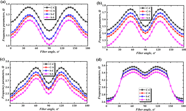
Figure 4. Variation characteristics of frequency of the laminated composite conical-cylindrical coupled shell with the increase of fiber direction angle, (a)-mode1, (b)-mode2, (c)-mode3, (d)-mode4.
Download figure:
Standard image High-resolution imageNext, the variation characteristics of frequency of the laminated composite conical-cylindrical coupled shell are considered according to the increases of the elastic modulus ratios when the fiber direction angles are [0°/90°/0°]. As can be seen in figure 5, same as individual shells [52], as the elastic modulus ratio increases, the frequency of conical-cylindrical coupled structure also increases.

Figure 5. Variation of frequency values of cross-ply [0/90/0] the laminated composite conical-cylindrical coupled shells with different ratio elastic modulus ratios, (a): C–C, (b): S–S, (c): C-F.
Download figure:
Standard image High-resolution imageLastly, the variation characteristic of frequency is considered according to the change of geometric parameters of individual shells. First, under the several classical boundary conditions, the variation characteristics of frequency of the coupled structure are studied increasing the length of conical shell when the geometric parameters of conical shell are constant. The material and geometric parameters used are same as above. Figure 6 shows the variation characteristics of frequency of the coupled structure according to the increase of length of the conical shell. As can be seen in figure 6, when other geometric parameters are constant, the frequency of coupled structure decreases as the length of conical shell increase. Especially, it can be known that when the length increases, the frequency decreases rapidly at the first time and then slowly again beyond a certain limitation.
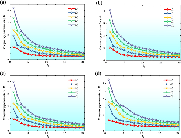
Figure 6. Variation of frequency parameters of the coupled structure with the increase of length of the conical shell (a); C–C, (b); C–S, (c); S–S, (d); F–C.
Download figure:
Standard image High-resolution imageNext, when the semi-vertex angle of conical shell increases, the variation characteristics of frequency of the coupled structure are investigated under the several elastic boundary conditions. As can be seen in figure 7, as the semi-vertex angle of conical shell increases, the frequency of coupled structure also increases.

Figure 7. Variation of frequency parameters of the coupled structure with the increase of semi-vertex angle of the conical shell, (a)-mode1, (b)-mode2, (c)-mode3, (e)-mode4.
Download figure:
Standard image High-resolution image
4. Conclusion
This paper provides an effective solution method based on the Haar wavelet for the analysis of free vibration characteristics of the laminated composite conical-cylindrical coupled shell. The first order shear deformation theory is applied to formulate the theoretical model of coupled structure. The displacement and rotation components of combinational structure are expressed by the Haar wavelet series along the axis direction and by the Fourier series along the circumferential direction. The integral constant is determined by the boundary condition. The boundary and continuity conditions are generalized by applying the artificial elastic boundary technique. The efficiency and accuracy of the proposed method is validated in the free vibration analysis of the coupled structures with various geometric and material parameters. Several new results on the laminated composite conical-cylindrical coupled shell are obtained through the analysis of parameters, and these numerical results can be used as benchmark materials in this field. The advantage of the proposed method consists in its simplicity, fast convergence and excellent accuracy.
Acknowledgments
The authors would like to thank the anonymous reviewers for carefully reading the paper and their very valuable comments. The authors also gratefully acknowledge the supports from Pyongyang University of Mechanical Engineering of DPRK. In addition, the authors would like to take the opportunity to express my hearted gratitude to all those who made contributions to the completion of my article.
Data availability statement
All data that support the findings of this study are included within the article (and any supplementary files).
Disclosure statement
No potential conflict of interest was reported by the authors.
Appendix A
Appendix B
Conical shell
Cylindrical shell


Appendix C