


Abstract
The quest to realize new kinds of data storage devices has motivated recent studies in the field of magnetoelectric heterostructures. One of the most commonly investigated systems is Fe3O4/[Pb(Mg Nb
Nb O3]0.7–[PbTiO3]0.3 (PMN-PT), however, the interplay between different coupling mechanisms is not yet well understood. To disentangle the role of strain and polarisation influence in Fe3O4/PMN-PT, we report on magnetoelectric coupling measurements for different orientations of the applied magnetic field and for two different substrate cuts, PMN-PT(001) and PMN-PT(011). For Fe3O4/PMN-PT(011), having the sample aligned such that the magnetic field is parallel to the [01
 ] easy axis leads to a remanent increase of the magnetisation for each electric field cycle. On the other hand, for the magnetic field along the [100] hard axis, the magnetisation follows a butterfly-like loop characteristic of strain coupling imparted by the substrate. For Fe3O4/PMN-PT(001), the magnetoelectric effect is a superposition of the observed behaviour of both in-plane directions in Fe3O4/PMN-PT(011). The magnetisation shows an initial remanent increase followed by a butterfly like loop. Polarised neutron reflectometry measurements on Fe3O4/PMN-PT(011) shows no difference between the behaviour at the interface and the bulk of the film and no decline of the interaction further away from the shared interface. Our results demonstrate the role of strain and polarisation on the magnetisation of the Fe3O4 layer and provide a clear step towards the design of future magnetoelectric systems.
Export citation and abstract BibTeX RIS

Original content from this work may be used under the terms of the Creative Commons Attribution 4.0 license. Any further distribution of this work must maintain attribution to the author(s) and the title of the work, journal citation and DOI.
1. Introduction
In the field of information technology, the control of magnetism to store and read information is one of the central topics. To manipulate the magnetic state for a new generation of devices, a multitude of different approaches are pursued, such as spintronics in the form of magnetic access memory [1] or racetrack memories [2, 3]. Another avenue is the use of multiferroic devices which combine ferro–/ferrimagnetism with ferroelectricity and allow for the direct control of the magnetisation by voltage [4, 5]. However, this effect is limited to low temperatures and exceedingly rare single-phase multiferroics. A possible solution to this is multiferroic heterostructures, which consist of individual ferromagnetic and ferroelectric layers that are coupled by a shared interface. Using complex oxides to build these heterostructures offers an extensive avenue to access a variety of exotic properties that could be tuned by an electric field [6], because of their strong couplings between lattice, charge, spin, and orbital degrees of freedom [7–9]. Oxide thin films often exhibit a much larger screening length compared to metallic systems [10], guaranteeing a strong electric field effect for the manipulation of magnetic properties. Among the oxide systems, Fe3O4 (magnetite) has been extensively investigated as a promising spintronic material for several decades. It possesses a high Curie temperature (850 K) and extremely high (∼100%) spin polarisation. It is ferrimagnetic in nature and shows a characteristic structural phase (Verwey-) transition at 120 K (cubic inverse spinel to monoclinic) [11–13].
In this paper, we study artificial heterostructures of Fe3O4 thin films on [Pb(Mg Nb
Nb O3]0.7–[PbTiO3]0.3 (PMN-PT), with the orientations PMN-PT(001) and PMN-PT(011). As the polarisation direction in PMN-PT is in the
  111
111 direction, the substrate cuts used here differ greatly in their strain and polarisation properties (figure 1). For PMN-PT(001), the in-plane directions [100] and [010], are equivalent and the polarisation has always an out-of-plane and in-plane component. If an electric field is applied along [001], the strain follows a butterfly loop with initial tensile strain regime as the polarisation tilts out-of-plane. Upon reaching the coercive field, the strain decreases and becomes more and more compressive until the maximum field. As the field is ramped down, the strain reverts back to zero [14]. The polarisation is hysteretic [15] and the lateral piezoelectric coefficient is d13 = d
 pC/N.
pC/N.

Figure 1. Sketch of structure, polarisation directions and strain for PMN-PT(001) and PMN-PT(011). The structure is shown in (b) and (c), where the cut directions is shown by a blue plane. The polarisation directions are shown by the green (in-plane and out-of-plane components) and blue (only in-plane) arrows. The strain loops are shown in (a) and (d) along with the polarisation directions at different electric fields.
Download figure:
Standard image High-resolution imageFor PMN-PT(011), the two in-plane directions, [100] and [01 ], are not equivalent and have different responses to the electric field, with piezoelectric coefficients d
 pC/N (along [100] direction) and d32 = 1400 pC/N (along [01
 ] direction) [16, 17]. Along [100], the strain follows a butterfly loop similar to the case discussed above for PMN-PT(001). In the [01
 ] direction however, a large compressive remanent strain is present even for zero electric field. As the electric field is increased, a large strain jump towards the tensile regime occurs at the coercive field, as the polarisation vectors with an out-of-plane component antiparallel to the applied field switch to an in-plane direction. For a further increase of the electric field, the strain reverts back to the compressive regime as all polarisation vectors switch out-of-plane along the electric field.
In Fe3O4/PMN-PT(011) multiferroic structures, the Verwey transition can be tuned with electric field and even different non-volatile resistance states are exhibited [18–20]. While Fe3O4/PMN-PT(001) remains much less studied, in comparison with Fe3O4/PMN-PT(011) an assignment of the effects to the different crystal orientations was possible and sheds new light onto the magnetoelectric coupling behaviour of Fe3O4 thin films.
Here, we will show that Fe3O4/PMN-PT(001) and Fe3O4/PMN-PT(011) artificial multiferroic heterostructures exhibit magnetoelectric coupling effects that are dependent on the crystalline orientation of the sample in magnetic field and substrate cut, and discuss the origin of the coupling between ferroelectric substrate and ferrimagnetic film, using a combination of magnetometry and polarised neutron reflectometry investigations.
2. Experimental
Fe3O4 thin films were grown by pulsed laser deposition (PLD) on  mm3 PMN-PT substrates (Crystal GmbH) with (001) and (011) surface orientation. A Fe2O3 target (Kurt J. Lesker company) was ablated using a 50 W KrF laser operated at a wavelength of 248 nm, a pulse length of 25 ns, laser fluence of 1.5 J cm−2, and a frequency of 5 Hz. The PLD chamber has a base pressure of 1×10⁻⁷ mbar ( = 1×10⁻⁵ Pa). During deposition the chamber was filled with 2×10⁻⁶ mbar oxygen and the substrate was kept at 500 ∘C.
The crystalline quality and thickness of the magnetite films were determined using a Bruker D8 Discover diffractometer with a Cu K-α source (λ = 1.5406 Å) to perform x-ray diffraction (XRD) and reflectometry (XRR) measurements. The stoichiometric presence of the single-phase magnetite was verified using hard x-ray photoemission spectroscopy (HAXPES) measured at the P22 Beamline at DESY (Hamburg) [21].
High-resolution transmission electron microscopy (HRTEM) was performed on thin cross-section samples with the projection direction along the [100] and [01 ] directions of the PMN-PT(011) substrate. The cross-sections were extracted by focused ion beam (FIB) milling using a standard procedure with an FEI Helios NanoLab 460F1 FIB-SEM [22]. High-resolution micrographs were acquired with an image-
 -corrected FEI Titan 80–300 transmission electron microscope operated at an accelerating voltage of 300 kV [23]. The aberrations of the imaging system were corrected to small values in order to avoid delocalisation of the signal by the electron optics. A Gatan Ultrascan 1000P CCD detector with a 20482 array of 14 µm large pixels was used to record the electron micrographs. The image magnification was calibrated by analysing the apparent spacings recorded with a silicon sample.
For study of the magnetic properties a Quantum design magnetic property measurement system MPMS SQUID system was used along with a high voltage power supply to study the magnetoelectric coupling effect, based on a design of Borisov et al [24]. To gain deeper insight on the magnetisation modulation along depth of the magnetite film as well as the interface, polarised neutron reflectometry (PNR) measurements were performed at the polarised beam reflectometer instrument at the NCNR (NIST Center for Neutron Research, NIST, Gaithersburg). Polarisation analysis was used to measure all four channels (two spin-flip and two non spin-flip) and deduce the direction of the magnetisation in the film.
3. Results
3.1. Structural characterisation
XRR measurements were performed on Fe3O4/PMN-PT(001) and Fe3O4/PMN-PT(011) to determine the interfacial quality between the deposited thin films and substrate as well as the film thickness (see supplemental figure S1). Using the GenX software [25] to fit the XRR curves reveals a Fe3O4 thickness of 359 Å for Fe3O4/PMN-PT(001) and 441
 Å for Fe3O4/PMN-PT(011) (see supplementary table S1). To fit the measurements, a thin top layer of reduced density had to be assumed. The films are quite smooth, with a roughness below 10 Å for both substrate orientations, whereas the substrate–film interface for Fe3O4/PMN-PT(011) is relatively rough with 18 Å.
XRD measurements reveal only Fe3O4 and substrate peaks, indicating the absence of excess phases and the high crystalline quality of the samples (see supplemental figure S2). From the peaks it is clear that film and substrate are oriented in parallel, i.e. the Fe3O4[001] PMN-PT[001] and Fe3O4[011]
 PMN-PT[011]. The XRD peaks of the films do not exhibit Laue oscillations as the single crystalline volume is rather small.
To confirm the Fe3O4 stoichiometry, hard x-ray photoelectron spectroscopy was performed using 6 keV photon energy to probe the Fe 2p core levels (figure 2). It is observed that the Fe 2p and 2p
 peaks situated at around 711 eV and 724 eV exhibit a main peak and a shoulder on the lower binding energy side (∼709.2 eV). These features are indicative of the existence of both Fe2+ and Fe3+ cations. The characteristic satellite peaks at 715.5 eV and 719 eV, which are typically attributed to to Fe2+ and Fe3+ respectively in either FeO or Fe2O3, merge for Fe3O4. The Fe 2p multiplet structure confirms the formation of stoichiometric Fe3O4. A more detailed HAXPES investigation of a similar Fe3O4 film grown using the same PLD system was performed in [26–29].

Figure 2. HAXPES study of Fe3O4/PMN-PT(011). The Fe 2p core levels are probed with photons of energy 6000 eV. The figure shows the Fe 2p1/2 and 2p3/2 peaks as well as reference spectra from literature (Fe2O3 and Fe3O4 from [30] and FeO from [31]).
Download figure:
Standard image High-resolution imageHRTEM images were taken to study the crystalline structure and epitaxy of Fe3O4/PMN-PT(011). HRTEM images recorded at high magnification as displayed in figure 3(a) show that the Fe3O4 layer is crystalline and essentially grown epitaxially on the substrate. Modulations of the lattice fringes are apparent, indicating the presence of lattice defects at high density. These defects compensate a relative difference of about 5% between the lattice constants along the interface of substrate and layer material. The Fourier analysis on the projected area of the Fe3O4 layer in figure 3(b) also indicates no significant variation of crystal orientation along the interface.

Figure 3. (a) HRTEM image of Fe3O4/PMNT-PT(011) showing low-frequency contrast modulation in the layer. These modulations indicate the presence of defects at high density compensating a difference in lattice constant between substrate and layer material. (b) Amplitudes of the image Fourier spectra taken from (a). The top half shows the spectrum of the projected Fe3O4 layer. This is compared to the spectrum of the substrate shown in the bottom half. Two Bragg peaks indices of Fe3O4 are given for orientation and the spacings of the reciprocal lattices along the direction of the interface are noted.
Download figure:
Standard image High-resolution image3.2. Magnetic measurements
For Fe3O4/PMN-PT(001) and Fe3O4/PMN-PT(011) the Verwey transition of Fe3O4 is clearly visible in zero-field-cooled field-warming (ZFC) and field-cooled warming magnetisation measurements (figures 4(a) and (b). From the derivative of the magnetisation, the Verwey transition temperature is determined to be  = 106 K for Fe3O4/PMN-PT(001) and
  = 126 K for Fe3O4/PMN-PT(011).
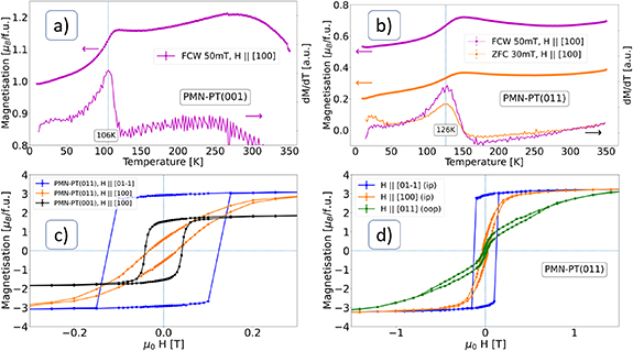
Figure 4. Magnetisation measurements with magnetic field along [100] for (a) Fe3O4/PMN-PT(001) and (b) Fe3O4/PMN-PT(011). The Verwey transition is clearly visible, especially in the derivative plot. The samples were either cooled in zero applied magnetic field (ZFC) or applied field (FCW) and measured with applied field during warming up. (c) Magnetic hysteresis loops at 300 K of Fe3O4/PMN-PT(001) and Fe3O4/PMN-PT(011) with the magnetic field applied in-plane. (d) Magnetic hysteresis loops at 300 K of Fe3O4/PMN-PT(011) with the magnetic field applied in-plane (ip) and out-of-plane (oop).
Download figure:
Standard image High-resolution imageHysteresis measurements reveal an in-plane anisotropy for Fe3O4 film on PMN-PT(011) and a magnetic easy axis along the [01 ] substrate direction (figures 4(c) and (d)). This observation agrees well with the findings for Fe3O4 bulk single crystals [32]. Interestingly, the saturation magnetisation of 3.2 µB
for Fe3O4/PMN-PT(011) and 1.9 µB
for Fe3O4/PMN-PT(001) is much lower than the reported value of 4.0 µB
. The reason may be that parts of the sample are not crystalline as defects may cause a reduced saturation magnetisation [33]. As the HRTEM images discussed earlier reveal a high defect density, this can explain the reduced saturation magnetisation.
] substrate direction (figures 4(c) and (d)). This observation agrees well with the findings for Fe3O4 bulk single crystals [32]. Interestingly, the saturation magnetisation of 3.2 µB
for Fe3O4/PMN-PT(011) and 1.9 µB
for Fe3O4/PMN-PT(001) is much lower than the reported value of 4.0 µB
. The reason may be that parts of the sample are not crystalline as defects may cause a reduced saturation magnetisation [33]. As the HRTEM images discussed earlier reveal a high defect density, this can explain the reduced saturation magnetisation.
Taken together, the characterisation measurements discussed so far confirm that the Fe3O4 thin films are crystalline, reveal a clear Verwey transition and expected anisotropy. Fe3O4/PMN-PT(001) shows a lower structural quality than Fe3O4/PMN-PT(011).
3.3. Magnetoelectric measurements
To prove similar magnetoelectric behaviour of our samples to Fe3O4/PMN-PT(011) in literature [19], we performed magnetic hysteresis and ZFC measurements with constant applied electric field of 4 kV cm−1, which is the maximum value in our measurement setup. We found that the coercive field reduced and the Verwey temperature shifted to lower values (see supplemental figures S3 and S4), in agreement with the literature [19].
Here, we investigate the effect of sweeping the electric field on the magnetisation of our sample, while in a constant in-plane magnetic field of 50 mT at 300 K. The field was chosen such that it almost saturates the magnetisation along the easy axis (magnetisation of 3.20 µB at saturation and 2.97 µB at 50 mT after saturation). For all measurements presented here, the electric field loops start at 0 kV cm−1. The electric field is then increased by 0.02 kV (cm·s)−1 up to +4 kV cm−1, decreased to −4 kV cm−1 and finally increased again back to 0 kV cm−1, completing the loop.
3.3.1. Fe3O4/PMN-PT(011)
Magnetoelectric measurements on Fe3O4/PMN-PT(011) were performed in [100] and [01 ] direction. To ensure the results are independent of the magnetic history, each sample was broken into several pieces and the measurements for different in-plane orientations were performed using different sample pieces.
Interestingly, the magnetoelectric behaviour of Fe3O4/PMN-PT(011) is strongly dependent on the orientation of the applied magnetic field. Figures 5(a) and (b) show the magnetoelectric behaviour for the magnetic field along [01 ]. Sweeping the electric field between the maximum values increases the magnetisation monotonically. First the magnetisation of the Fe3O4 layer increases linearly with low slope up to about 1.7 kV cm−1 with increasing electric field. Then a large jump of the magnetisation is observed, followed again by a slight linear increase up to the maximum applied electric field of 4 kV cm−1. As the electric field is ramped to negative values, the magnetisation increases linearly again and shows a jump around −1.5 kV cm−1. This behaviour continues for subsequent electric field cycles between ±4 kV cm−1. However, the total increase in magnetisation reduces for subsequent loops and is always higher as the electric field is swept from negative to positive values than for the opposite (figure 5(b)). The jump occurs at roughly the coercive field of electrical polarisation and maximum tensile strain of the PMN-PT substrate [34]. Since the magnetisation increase per cycle is steadily reducing and already close to zero for the last cycle measured here, we expect the magnetisation to reach a saturation value for further cycling. Indeed, the magnetisation at zero electric field follows a reciprocal function, which reveals that the magnetisation approaches 1.08 µB
(see supplemental, figure S5).
]. Sweeping the electric field between the maximum values increases the magnetisation monotonically. First the magnetisation of the Fe3O4 layer increases linearly with low slope up to about 1.7 kV cm−1 with increasing electric field. Then a large jump of the magnetisation is observed, followed again by a slight linear increase up to the maximum applied electric field of 4 kV cm−1. As the electric field is ramped to negative values, the magnetisation increases linearly again and shows a jump around −1.5 kV cm−1. This behaviour continues for subsequent electric field cycles between ±4 kV cm−1. However, the total increase in magnetisation reduces for subsequent loops and is always higher as the electric field is swept from negative to positive values than for the opposite (figure 5(b)). The jump occurs at roughly the coercive field of electrical polarisation and maximum tensile strain of the PMN-PT substrate [34]. Since the magnetisation increase per cycle is steadily reducing and already close to zero for the last cycle measured here, we expect the magnetisation to reach a saturation value for further cycling. Indeed, the magnetisation at zero electric field follows a reciprocal function, which reveals that the magnetisation approaches 1.08 µB
(see supplemental, figure S5).

Figure 5. Magnetoelectric measurement for sample Fe3O4/PMN-PT(011) showing multiple loops for +50 mT applied along both in-plane directions at 300 K. (a) Magnetic field along [01 ]. (b) shows the relative change in magnetisation in the linear regime (blue dashed lines in (a) with a linear fit. The half-integer loop numbers denote a change of the electric field from positive to negative, while integer numbers relate to a sweep from negative to positive. The blue lines are a linear fit to guide the eye. (c) Magnetic field along [100], with (d) showing a clear and steady butterfly behaviour, several loops after (c). The error bars represent ± 1 standard deviation.
Download figure:
Standard image High-resolution imageIf the magnetic field is applied along [100], the magnetoelectric behaviour of the sample is different (see figures 5(c) and (d)). For the initial electric field ramp to +4 kV cm−1, the increase of the magnetisation is linear. Only at the beginning of the cycling a small initial jump of the magnetisation after applying the electric field for the first time is observed. As the electric field is decreased, the magnetisation decreases until about −1.5 kV cm−1. Then it increases again until the minimum electric field value of −4 kV cm−1 is reached. Increasing the electric field from −4 kV cm−1 to +4 kV cm−1 leads to similar behaviour, first a decrease in magnetisation and then a jump at around 1.7 kV cm−1. Overall, the magnetisation shows a remanent increase for one full electric field cycle, however for subsequent cycles, this increase diminishes. After few additional electric field loops, the remanent magnetisation reproduces its values and follows a butterfly like curve, which resembles the strain imparted by PMN-PT (figure 5(d)). However, the butterfly loop is not symmetric as one would expect based on the strain (see figure 1) and the crossover point (point at which the loop intersects itself) is offset towards negative electric field. The magnetoelectric behaviour has been reproduced on several Fe3O4/PMN-PT(011) samples. The asymmetry and crossover points are strongly sample dependent with some samples showing a nearly symmetric butterfly loop and a crossover point at 0 kV cm−1 while others are very asymmetric with a crossover point at −1 kV cm−1. The lowest magnetisation is reached at the electrical coercive field, i.e. at the highest tensile strain, while the magnetisation increases for compressive strain.
The SQUID measurements clearly reveal magnetoelectric coupling in the sample. However, as the integrated magnetisation of the sample is probed, the separation of interface effects and bulk behaviour is not possible. Therefore, investigation of magnetisation with depth resolution may provide with more detailed information on the switching mechanism and helps to localize the different effects. If the coupling is mainly concentrated in the interface region, a large change of magnetisation will be observed in this region and only little change in the rest of the film. PNR is the method of choice for such a question, since it provides information about the magnitude and orientation of the magnetisation in depth resolution.
The geometry of the experiment is shown in figure 6. The sample is oriented such that the magnetic field and neutron polarisation is along [01 ]. The neutron propagation direction is along [100]. The electric field is applied in out-of-plane [011] direction by four Ag paint contacts and thin Pt wires on the top. On the bottom of the sample an Au layer of about 30 nm was deposited for grounding the bottom of the substrate. The magnetic and electric fields are thus applied in the same directions as in the SQUID measurements in figure 5(a).

Figure 6. Sketch of the sample geometry for polarised neutron reflectometry. In the experiment the electric field was applied using four contacts on the top (only one shown here).
Download figure:
Standard image High-resolution imageThe PNR curves were recorded with full polarisation analysis to capture the full vector information of the magnetisation in depth resolution [35]. The neutron beam is polarised prior to scattering from the sample in either up (u) or down (d) direction, i.e. parallel or anti-parallel to the magnetic field. After scattering, the analyser filters out neutrons of either up or down direction. Thus, four channels can be observed: up-up (uu) and down-down (dd); these are the so-called non-spin flip channels; and up-down (ud) and down-up (du), the so-called spin flip channels. The non-spin flip channels are sensitive to an alignment of the magnetisation parallel/antiparallel to the neutron polarisation and magnetic field and thus probe the component of the magnetisation parallel to the magnetic field. The spin flip channels, ud and du, are sensitive to the in-plane component of the magnetisation perpendicular to magnetic field. Out-of-plane magnetic moments cannot be detected by PNR, but, as the sample exhibits strong in-plane anisotropy and the magnetic field is applied in-plane, the out-of-plane magnetisation component is expected to be negligible.
In figure 7 the PNR measurement for 0 kV cm−1 is shown. The splitting between the uu and dd channels confirms that the sample is magnetic. As a spin flip signal is present, we conclude that part of the magnetisation is not parallel to the magnetic field.
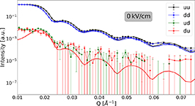
Figure 7. PNR measurements with fit of Fe3O4/PMN-PT(011) at 0 kV cm−1. Error bars represent ± 1 standard deviation.
Download figure:
Standard image High-resolution imageFor comparison of the neutron reflectometry measurements with the SQUID results shown earlier, a similar electric field measurement as in figure 5(a) was performed and reflectometry curves were recorded at the electric fields: 0 kV cm−1, +2 kV cm−1, +4 kV cm−1, −4 kV cm−1, and +4 kV cm−1. The corresponding PNR curves are given in the supplemental, figure S6. Additionally, during the electric field ramping, single point intensity measurements were taken at Q = 0.02 Å−1 without analyser in both polarisation directions, u and d, and used to calculate the spin asymmetry  . The Q-value was chosen such that the intensity is high and the splitting between up and down channels is pronounced. As the asymmetry is related to the magnetisation of the sample it can be compared to the SQUID measurements (figure 8). The similar behaviour is evident and thus confirms that the sample behaviour is reproducible.

Figure 8. Comparison of the magnetoelectric coupling measurement of Fe3O4/PMN-PT(011) with PNR spin asymmetry at Q = 0.02 Å−1. Error bars represent ± 1 standard deviation.
Download figure:
Standard image High-resolution imageFrom the fit of the PNR experiment, a nuclear scattering length density (SLD) profile can be extracted (similar to XRR), as well as a magnetic scattering length density (mSLD) profile, which reveals the depth resolved magnetisation.
The programs Reductus and Refl1D were used for data reduction and analysis of the reflectometry curves [36, 37]. The model consists of the substrate, the Fe3O4 layer, and a top layer. The top layer was introduced based on XRR measurements, which showed a thin top layer of reduced SLD. To maintain a coherent model, all five data sets recorded at different electric fields were fit together, keeping the SLD of the substrate and the Fe3O4 layer the same. The Fe3O4 thickness in measurements 1 and 2 was allowed to be fit, to take into account initial structural changes upon the first application of voltage while the thickness for measurements 3–5 was kept fixed to the thickness of measurement 2. The magnetic SLD, magnetisation angle of the Fe3O4 layer and top layer parameters were allowed to vary independently. The fit parameters are listed in the supplemental.
From the fit of the measurements, an SLD profile was extracted (figure 9). For the measurement at 0 kV cm−1, the magnetic SLD of the top layer is significantly higher than that of the Fe3O4 layer. With the application of voltage, the mSLD of the top layer nearly remains constant, while the Fe3O4 layer mSLD increases for each subsequent measurement. In the last measurement, at +4 kV cm−1, the mSLD of the total film is constant. One might speculate that including a thin layer between substrate and Fe3O4 might result in an improvement of the fit, as it would account for a possible relaxation of the static or electric field induced strain or other interface effects. As this does not improve the fit, we may conclude the interface between substrate and film possesses the same magnetic properties as the Fe3O4 layer and the strain is transferred to the whole layer.

Figure 9. Scattering length density profiles (full lines represent nuclear SLD and dashed lines magnetic SLD) from the fit of the PNR measurements.
Download figure:
Standard image High-resolution imageAs fully polarised PNR is sensitive to the orientation of the magnetisation, the fit also reveals a change in magnetisation angle relative to the magnetic field (supplemental figure S7). Initially, the magnetisation within the Fe3O4 layer is canted away from the magnetic field in [01 ] direction by about 32∘, which is not surprising, as the applied magnetic field of 50 mT is not enough to saturate the sample. With increasing electric field, the angle of the Fe3O4 magnetisation to the magnetic field decreases, i.e. the magnetisation rotates towards the applied magnetic field.
One might notice that the total change in magnetic SLD of 41% between the first and last measurement is significantly higher than the magnetisation change of 8% for the corresponding SQUID measurement. This could be due to the preceding exposure of the sample to voltage and magnetic field during the PNR measurement, relative to the SQUID measurements taken later in time, or maybe due to a slightly different magnetic field environment.
3.3.2. Fe3O4/PMN-PT(001)
For comparison, another sample was prepared on PMN-PT(001). PMN-PT(001) has two equivalent in-plane directions and the strain follows a butterfly loop similar to PMN-PT(011) in [100] direction. The magnetoelectric response of Fe3O4/PMN-PT(001) is therefore expected to be a superposition of the response for both directions of the Fe3O4/PMN-PT(011), with a remanent increase, a butterfly loop, and asymmetry. This is because the two orthogonal in-plane directions in PMN-PT(001) are equivalent and show the same strain behaviour, as opposed to the case of PMN-PT(011), where they are drastically different.
Figure 10(b) shows the change in magnetisation of Fe3O4/PMN-PT(001) while ramping the electric field between ±4 kV cm−1 in a static magnetic field of 50 mT applied along [100] direction at 300 K. The initial electric field loop is very similar to the case of Fe3O4/PMN-PT(011) for the magnetic field along [01 ]. Initially, a linear increase of the magnetisation is observed, followed by a jump at around 1.3 kV cm−1 and a linear increase until +4 kV cm−1. Upon decreasing the electric field, the magnetisation increases linearly up to about −1.6 kV cm−1, where another jump occurs. The total change for the first complete loop in +50 mT is about 0.2 µB
/f.u. This increase can be repeated with quickly diminishing amplitude for subsequent loops. For all loops after the second, the magnetisation crosses itself and shows a butterfly like curve (figure 10(a)). There is still a small remanent change, although the change per loop is less than 0.01 µB
/f.u. The butterfly shape of the later loops resembles the butterfly loop of the strain, with the tensile strain regime exhibiting lower magnetisation and the compressive strain regime exhibiting higher magnetisation. As the magnetoelectric behaviour of Fe3O4/PMN-PT(001) follows first a remanent increase of magnetisation followed by an asymmetric butterfly shape, we can conclude that this is a combination of both directions of Fe3O4/PMN-PT(011), confirming our initial expectation. We expect that for further electric field cycles, the remanent magnetisation increase per cycle diminishes and for the magnetisation to follow a steady butterfly loop akin to figure 5(d).
]. Initially, a linear increase of the magnetisation is observed, followed by a jump at around 1.3 kV cm−1 and a linear increase until +4 kV cm−1. Upon decreasing the electric field, the magnetisation increases linearly up to about −1.6 kV cm−1, where another jump occurs. The total change for the first complete loop in +50 mT is about 0.2 µB
/f.u. This increase can be repeated with quickly diminishing amplitude for subsequent loops. For all loops after the second, the magnetisation crosses itself and shows a butterfly like curve (figure 10(a)). There is still a small remanent change, although the change per loop is less than 0.01 µB
/f.u. The butterfly shape of the later loops resembles the butterfly loop of the strain, with the tensile strain regime exhibiting lower magnetisation and the compressive strain regime exhibiting higher magnetisation. As the magnetoelectric behaviour of Fe3O4/PMN-PT(001) follows first a remanent increase of magnetisation followed by an asymmetric butterfly shape, we can conclude that this is a combination of both directions of Fe3O4/PMN-PT(011), confirming our initial expectation. We expect that for further electric field cycles, the remanent magnetisation increase per cycle diminishes and for the magnetisation to follow a steady butterfly loop akin to figure 5(d).
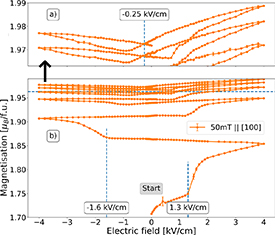
Figure 10. Magnetoelectric measurement of Fe3O4/PMN-PT(001) showing multiple loops for +50 mT at 300 K. The top image shows a magnification of the upper part from the dashed line onwards. The electric field is applied along [001] and the magnetic field along [100].
Download figure:
Standard image High-resolution image4. Discussion
From the measurements discussed above, we can determine the coupling mechanisms responsible for the change of magnetisation with the electric field. First, it is evident that the effects experienced by magnetite on PMN-PT(001) are a superposition of the effects found for the two different in-plane directions of magnetite on PMN-PT(011). Second, as the strain experienced by PMN-PT(011) is only dependent on the electric field direction, which is the same for both orientations of the sample in the magnetic field, the behaviour for the two in-plane directions are controlled by the magnetic anisotropy along the respective axis. Third, there may be two different effects responsible for the magnetoelectric coupling behaviour in Fe3O4/PMN-PT(011) i. e. strain mediated magnetostriction and polarisation coupling.
To examine the magnetoelectric coupling, we will first discuss the origin of strain and polarisation coupling, starting with strain. The magnetostriction constants of magnetite are  and
and  [38]. For a negative magnetostriction constant the magnetisation decreases for applied positive (tensile) strain and increases for applied negative (compressive) strain. Hence, the strain in PMN-PT(001) and PMN-PT(011) for small electric fields in the [100] direction is tensile and reaches its maximum value at the electric coercive field, EC
(see figure 1 for an overview of the strain behaviour). For higher electric fields the strain decreases and becomes compressive up to the maximum applied field. The strain is independent of the sign of the applied electric field. Hence, the strain of PMN-PT along [100] direction is forming a so-called butterfly loop. If the magnetisation of magnetite in Fe3O4/PMN-PT(001) and Fe3O4/PMN-PT(011) with the magnetic field along [100] were only dependent on strain, it should exhibit an inverted butterfly loop as magnetostriction constant is negative.
[38]. For a negative magnetostriction constant the magnetisation decreases for applied positive (tensile) strain and increases for applied negative (compressive) strain. Hence, the strain in PMN-PT(001) and PMN-PT(011) for small electric fields in the [100] direction is tensile and reaches its maximum value at the electric coercive field, EC
(see figure 1 for an overview of the strain behaviour). For higher electric fields the strain decreases and becomes compressive up to the maximum applied field. The strain is independent of the sign of the applied electric field. Hence, the strain of PMN-PT along [100] direction is forming a so-called butterfly loop. If the magnetisation of magnetite in Fe3O4/PMN-PT(001) and Fe3O4/PMN-PT(011) with the magnetic field along [100] were only dependent on strain, it should exhibit an inverted butterfly loop as magnetostriction constant is negative.
For PMN-PT(011), the strain along the other in-plane direction, [01 ], is in a strongly compressive state without applied field. At the coercive electric field the strongly compressive strain sharply relaxes, however a smaller compressive strain still remains. As the electric field is only slightly increased, the strain jumps back towards the strongly compressive regime almost instantly. Given the positive magnetostriction constant along [01
 ], the jump towards the positive strain will increase the magnetisation in magnetite.
The second effect present in the system is polarisation coupling (sometimes also called charge coupling). As an electric field is applied, the polarisation caused by the field leads to a charge imbalance at the top and bottom interface of the substrate (see figure 11). For negative voltage applied at the top of sample, the polarisation in the substrate will cause a positive charge to accumulate at the film-substrate interface and a negative charge to accumulate at the bottom surface of the substrate. The positive charge at the film-substrate interface induces an electron accumulation in the magnetite layer to compensate. As the Fe-3d orbitals are (more than) half filled, an electron accumulation will result in the reduction of the magnetisation, as the spin of the accumulated electrons has to be anti-parallel to those of the already present electrons, thereby reducing the overall magnetisation. Conversely, a positive voltage will lead to a depletion of electrons in magnetite and cause the magnetisation to increase. For other systems, such as the commonly investigated La Sr
Sr MnO3 (LSMO), the effect of charge accumulation and depletion is opposite to the one discussed here, as the Mn-3d orbital is less than half filled for LSMO [39]. The polarisation coupling is dependent on the polarisation of PMN-PT with applied electric field and thus anti-symmetric regarding the sign of the electric field, in contrast to the strain coupling discussed above.

Figure 11. Polarisation and related charge accumulation or depletion.
Download figure:
Standard image High-resolution image
To find out which coupling mechanisms are relevant for each direction of magnetic field and substrate orientation, we will first review the Fe3O4/PMN-PT(011) sample with the magnetic field applied along [01 ]. Here, the magnetoelectric coupling shows a fully remanent increase (figure 5), with a significant jump of the magnetisation around the electrical coercive field of PMN-PT. If the strain is responsible for the magnetoelectric coupling, tensile strain (or rather a significant reduction of the large compressive strain) will increase the magnetisation of Fe3O4, as the magnetostriction constant along [011] is positive (see above). This fits exactly to the observed behaviour. At the strain jump the magnetisation drastically increases in the SQUID measurements. As the magnetisation alignment along the easy axis is initially suppressed by compressive strain, the strain jump towards the tensile regime also favours a reorientation in the direction of the easy axis, which is confirmed by the PNR measurements.
The measurements shown here are mostly bulk sensitive methods, which cannot resolve the microscopic changes on magnetisation. For further study, it would be very interesting to use a method that can image the individual magnetic domains, e.g. MOKE microscopy, to follow their change with voltage. One would expect that the switching of ferroelectric domains in the PMN-PT drives domain wall motion in magnetite, which, combined with the external magnetic field, leads to growth of domains with magnetisation along the easy axis.
Along with strain, polarisation of PMN-PT and associated charge accumulation and depletion in Fe3O4 also has an influence here. As shown in figure 5(b), there is an asymmetry in the remanent increase related to the direction of the electric field change, with a stronger increase as the electric field is ramped from negative to positive.
Also of interest would be to study the effects of a long series of electric field cycles on the magnetoelectric response. If the substrate starts to show fatigue, the charge and strain response would change, affecting the magnetisation of Fe3O4 [40]. Here, however, as the number of cycles was low, we do not expect fatigue to play a major role in the magnetoelectric coupling.
For Fe3O4/PMN-PT(011) with the magnetic field applied along [100], the behaviour is quite different. Following the discussion above about the butterfly shape of the strain along [100] and negative magnetostrictionalong [100], the magnetoelectric coupling should show a behaviour similar to the strain imparted by PMN-PT but inverted. As shown in figure 5(d), the strain along [100] is indeed responsible for the overall shape of the magnetoelectric coupling, however additional contributions are present. First, the butterfly loop is asymmetric, with higher magnetisation for positive electric field. As strain is intrinsically not sensitive to the sign of the electric field, this has to be an effect of the polarisation coupling. Second, there is a much stronger decrease of the magnetisation at the electrical coercive field compared to PMN-PT(001), which is likely related to the large strain jump along [01 ], indicating a cross-coupling of the two in-plane strain directions.
For the Fe3O4/PMN-PT(001), the magnetoelectric coupling is obviously a superposition of the magnetoelectric behaviour of both crystal orientations discussed above for Fe3O4/PMN-PT(011). Initially, a remanent increase of the magnetisation occurs, as the magnetisation aligns with the magnetic field. The reason is the same as the remanent change of magnetisation in Fe3O4/PMN-PT(011), a realignment towards the easy axis. Then, after a few electric field cycles, the magnetisation follows a butterfly loop similar to the one discussed above for [100] direction, as the strain describes a butterfly loop. Also, polarisation coupling is present, as the butterfly loop is asymmetric [41].
5. Conclusion
We have investigated the magnetoelectric coupling in Fe3O4/PMN-PT(001) and Fe3O4/PMN-PT(011) heterostructures for a static, non-saturating magnetic field and discussed strain and polarisation contributions for different crystallographic directions of the sample. A reorientation of the magnetisation towards the easy axis ([01 ] for Fe3O4/PMN-PT(011) and [100] for Fe3O4/PMN-PT(001)) causes a remanent increase in magnetisation as the electric field is cycled between ±4 kV cm−1. Along [100] for both substrate cuts, the magnetisation follows a butterfly shape, similar to the strain exerted by the substrate. An additional polarisation coupling causes an asymmetry in the butterfly loop and shifts the crossover point towards negative field. In Fe3O4/PMN-PT(011), the orientation of the sample in the magnetic field significantly affects the magnetoelectric coupling, since the two in-plane directions possess a different anisotropy. In Fe3O4/PMN-PT(001), the separate effects are superimposed, as the directions are equivalent.
Acknowledgment
The authors acknowledge the support of the National Institute of Standards and Technology, U.S. Department of Commerce, in providing the neutron research facilities used in this work.
Certain commercial trade names are identified in this paper to foster understanding. Such identification does not imply recommendation or endorsement by the National Institute of Standards and Technology, nor does it imply that the materials or equipment identified are necessarily the best available for the purpose.
Data availability statement
The data that support the findings of this study are available upon reasonable request from the authors.
Supplementary data (4.6 MB PDF)