


Abstract
Topology is a crucial ingredient for understanding the physical properties of superconductors. Magnetic field crowds to adopt the form of topologically-protected quantum flux lines which can lose this property when moving at high velocities. These extreme conditions can be realized when superconductors undergo a thermomagnetic instability for which the sample topology come also into play. In this work, utilizing the magneto-optical imaging technique, we experimentally study magnetic flux avalanches in superconducting films with multiply-connected geometries, including single and double rings. We observe a domino effect in which avalanches triggered at the outer ring, stimulate avalanches at the inner ring thus impairing the expected magnetic shielding resulting from the outer ring and gap. We implement numerical simulations in order to gain more insight into the underlying physical mechanism and demonstrate that such event is not caused by the heat conduction, but mainly attributed to the local current distribution variation near the preceding flux avalanche in the outer ring, which in turn has a ripple effect on the local magnetic field profile in the gap. Furthermore, we find that the domino effect of thermomagnetic instabilities can be switched on/off by the environmental temperature and the gap width between the concentric rings. These findings provide new insights on the thermomagnetic instability in superconducting devices with complex topological structures, such as the superconductor–insulator–superconductor multilayer structures of superconducting radio-frequency cavities.
Export citation and abstract BibTeX RIS

Original content from this work may be used under the terms of the Creative Commons Attribution 4.0 licence. Any further distribution of this work must maintain attribution to the author(s) and the title of the work, journal citation and DOI.
1. Introduction
A unique hallmark of superconductivity is the capacity to carry electric current without dissipation. This quantum state is however, very sensitive to temperature, magnetic field, and even mechanical strain [1–4]. In particular, thin superconducting films exposed to a ramping magnetic field, may undergo thermomagnetic instabilities in the form of finger-like or tree-like flux avalanches. These catastrophic events can be directly observed via magneto-optical imaging (MOI) technique, as demonstrated in several superconducting materials, such as Nb [5, 6], MgB2 [1, 7], YBCO [8–10], Nb3Sn [11], Pb [12], NbN [13], Mo3Ge [14], as well as a-MoSi thin film [15]. The effect of controllable space modulations of the superconducting state in this event can be accomplished mainly by inserting artificial arrays of holes, cracks, and additional conducting layers in the superconducting systems [16–21].
Besides the thermodynamic parameters, the geometry and topology of the structure play a major role on the superconducting response. For instance, ring-shaped superconductors are widely found as key components in devices (e.g., permanent magnets, superconducting quantum interferences device, and magnetic bearings) [22–24]. In addition, they present significantly different magnetic behavior compared to the simply connected counterparts, including the static flux penetration and the development of dynamic thermomagnetic instabilities [25–27]. Unlike avalanches observed in simply connected structures, multiply connected MgB2 films (e.g., superconducting rings) have shown the presence of a crossing dendrite after several tree-like avalanches nucleate on the outer edge without reaching the inner rim [25]. This formation of a flux channel which has been coined magnetic perforation, significantly changes the local magnetic field at the edges and the shielding current in the ring. Recent experimental results in Nb demonstrated that such dendrites are triggered when the difference between the applied field and the average field inside the central hole ΔHth reaches a certain threshold level, an event that reproduces quasiperiodically with increasing applied field [27].
A ring-shaped superconductor exposed to a time-varying magnetic field is reminiscent of the cross-section of superconducting radio-frequency (SRF) cavities. In recent years, a superconductor–insulator–superconductor (SIS) structure has been proposed to be used in SRF cavities to arrest thermomagnetic avalanches triggered by local penetration of vortices at defects [28]. Kubo [29] discussed the magnetic field limit and the optimum layer thickness of such SIS multilayer structure for application in superconducting accelerating cavities. Wang et al [30] use TDGL theory to numerically investigate the effect of nanoscale defects, surface roughness, and cracks on the vortex penetration and superheating field in Nb3Sn–I–Nb multilayer structures. It is worth noting that both the critical state and thermomagnetic instability in the double ring structure are not simple superpositions of flux behavior in these layers, but novel features result from the interaction of these films, similarly to the physics described in [31]. Nevertheless, the macroscopic thermomagnetic instability in such superconducting rings with multiply-connected topological structure, especially the puzzling physical mechanism caused by the interaction between rings, remains largely unexplored.
The present work aims at investigating thermomagnetic instabilities in superconducting rings, with particular attention on the interactions between concentric rings. First, we experimentally study the flux avalanche morphologies in concentric superconducting rings exposed to an increasing applied field by magneto-optical (MO) technique, and observe a domino effect of flux avalanches in double rings. In order to gain more insight into the underlying physical mechanism, we implement numerical simulations to investigate the triggering conditions of thermomagnetic instabilities, the magnetic flux avalanches morphology, and the flux injected into the hole in superconducting films with multiply-connected geometries, including single and double rings. In addition, we also study how the flux avalanches in the outer ring affect the shielding current in this ring as well as the local magnetic field at the edge of the inner ring, and demonstrate that the domino effect of thermomagnetic instability in such system can be tuned by adjusting the gap width between the double rings. The paper is organized as follows: the experimental settings and the numerical method used to analyze the flux dynamics in superconducting rings are presented in section 2. In section 3, we present the MOI experimental results of flux avalanches in concentric rings. In addition, we discuss the simulated thermomagnetic instabilities and unveil the mechanism for the domino effect of flux avalanches. Finally, a summary of the most salient results is presented in section 4.
2. Experimental and numerical methods
2.1. Sample preparation and MOI technology
The MgB2 thin films were prepared by hybrid physical-chemical vapor deposition (HPCVD) developed by Xi et al [32]. Details of the HPCVD system used in this work can be found in references [33, 34]. Briefly, Mg ingots ( purity) were placed around a 5 × 5 × 0.3 mm MgO (111) substrate on a molybdenum susceptor, and heated up to 660 °C in 4 kPa ultrahigh pure hydrogen (
 purity). The deposition started as 5% B2H6 balanced with hydrogen were slowly flowed into the vacuum chamber at a rate of 3 sccm. 50 nm-thick MgB2 thin film were deposited on substrate after 4 min. The superconducting ring pattern schematically shown in figure 1(a) (with Ri1 = Ro1/2 = Ri2/3 = Ro2/4 = 0.5 mm) were obtained by photolithographic process by dry-etching with argon ion milling.

Figure 1. Schematic of the investigated samples. (a) Two concentric superconducting rings of inner radii Ri1 and Ri2 and outer radii Ro1 and Ro2 on a substrate exposed to a gradually increasing perpendicular magnetic field Ha. (b) A single superconducting ring of inner radius Ri and outer radius Ro. The red line shows the numerically calculated field profile of the z-component magnetic field Bz along the radius.
Download figure:
Standard image High-resolution imageThe MO technique is employed to observe the flux penetration in the concentric rings, where a Bi-doped yttrium iron garnet with in-plane magnetic domains placed on top of the superconducting specimen is used as an indicator film based on Faraday effect [35]. The sample was first zero-field-cooled to 4.3 K, and then an increasing magnetic field was applied perpendicular to the sample.
2.2. Numerical method
For a very thin superconducting film, exposed to an applied magnetic field perpendicular to the film plane, the electrodynamics follows Maxwell's equations:

with B = μ0 H and ∇ ⋅ J = 0, where J δ(z) is the current density with J the sheet current and δ(z) the delta distribution. The heat flow in the film is governed by the equation

where T is the local temperature in the superconductor, T0 is the base temperature which is kept at a constant value, d is the sample thickness and
J
⋅
E
represents the Joule heating. The thermal conductivity and the specific heat of the superconductor are κ and c, and h is the coefficient of heat transfer between the superconducting film and the substrate. The temperature dependencies of the thermal parameters are assumed as  ,
,  and
and  [36].
[36].
The relationship between current and electric field is described by the commonly used phenomenological model [37]

with a resistivity law

where ρ0 and ρn are a constant resistivity and the normal state resistivity, respectively. Jc is the critical sheet current density, and n is the so-called creep exponent. The E–J relationship is highly nonlinear and corresponds to Bean model when n → ∞. Here, the temperature dependence of Jc and n are taken as

where Jc0 and n0 are constants.
To solve the electromagnetic behavior, the sheet current is expressed through the local magnetization, g(x, y), as [38]

We can obtain the time derivative of g by the Biot–Savart law using the fast Fourier transform method as reported in reference [36]

where  is the two-dimensional spatial Fourier transform and k = |
k
|. This equation can be used to describe the dynamics of multiply-connected samples.
is the two-dimensional spatial Fourier transform and k = |
k
|. This equation can be used to describe the dynamics of multiply-connected samples.
For a thin superconducting film as the one shown in figure 1, the xy plane is divided into three parts: the superconductor, the area in the hole and the area outside the ring. Inside the superconductor,  can be obtained by combining Faraday's law with the constitutive equations (3) and (4) of the superconductor, given by

For the area outside the superconducting ring,  can be obtained by an iterative procedure that guarantees g = 0 outside the sample. For the area inside the hole, there are generally three different implementations to obtain
  that satisfies the boundary conditions of the hole (g is kept constant in the hole). (i) g in the hole area is set to the lowest value of the inner edge of the ring [39, 40]. This method is simple and flexible to implement. However, unphysical net flux will be introduced into the hole in this way. (ii) The hole is considered as part of the superconducting sample, but its critical current is strongly reduced (or the resistance is increased) [41, 42]. This method is physically feasible, but the calculation efficiency is penalized due to the reduction of the time step. (iii) A modified iterative procedure is used to find
  in the holes as reported by Vestgården et al [43, 44]. This approach does not require additional assumptions, but is more demanding from computational point of view. In what follows, we use the second method to model the holes. By testing different values of ρ, we find that ρ = ρn is large enough to make g = constant and J = 0 in the holes.
Numerical simulations are performed over a square of half-width L = 1.3Ro discretized on a 256 × 256 equidistant grid. The material parameters used in this calculation are typical for MgB2 films, with Tc = 39 K, Jc0 = 50 kA m−1, ρ0 = ρn = 7 μΩ cm [36]. We use n0 = 19 and limit n(T) to n(T) ⩽ 59 at low temperature. A weak quenched disorder is introduced by randomly decreasing Jc0 by 10% at 5% of the grid points. The thermal parameters are κ0 = 0.17 kW K−1 m−1, c0 = 35 kJ K−1 m− 3 and h0 = 220 kW K−1 m− 2. As we will be pointed out below, the numerically imposed ramp rate of the applied magnetic field is substantially larger than the ramp rate applied experimentally.
3. Results and discussions
3.1. Magneto-optical investigation
Figures 2(a)–(d) show MOI of concentric rings at different applied fields. The external field is ramped up in steps of 0.1 Oe, which is generated by a copper coil with resistance R = 22.1 Ω and inductance L = 26 mH. Since the corresponding time constant is τ = L/R ≈ 1 ms, a rate of about 100 Oe s−1 = 0.01 T s−1 is obtained. The brightness in these images represents the magnitude of the local magnetic flux density. In order to distinguish flux avalanches from the regular penetration, we display the differential images in figures 2(e)–(h), obtained by subtracting the corresponding previous images recorded at slightly lower magnetic fields from the upper panels, using the ImageJ software with the Image Calculator tool, as introduced in [25, 45–47]. The brightness here indicates an increase of the local magnetic flux with increasing applied field. At μ0 Ha = 0.31 mT, several flux avalanches are triggered exclusively in the outer ring, including magnetic perforation accompanied by sudden flux increase in the outer hole between the two rings [panels (a) and (e)].

Figure 2. MO images of a 50 nm-thick ring-shaped MgB2 film at T0 = 4.3 K (a)–(d), and the differential maps (e)–(h) obtained by subtracting consecutive recorded images, thus highlighting the avalanches occurring in the corresponding upper panels. Bright (dark) color indicates high (low) local magnetic fields. In panels (a) and (e) a magnetic perforation takes place at the outer ring. In panels (b) and (f) a magnetic perforation occurs in the inner ring, with a nucleation spot in the vicinity of the avalanche shown in (e). Simultaneous avalanches in the inner and outer ring are seen in panels (c) and (g), as well as short range dendritic avalanches [panels (d) and (h)].
Download figure:
Standard image High-resolution imageWhen the applied field reaches μ0 Ha = 0.49 mT, the first crossing dendrite appears in the inner ring as shown in panels (b) and (f). The increase in the flux field inside the central hole and the decrease of flux at the outer edge of the inner superconducting ring prove that a large amount of magnetic flux in the outer hole is injected into the central hole through this channel (i.e. magnetic perforation of the inner ring). With further increasing the applied field (e.g., μ0 Ha = 1.57 mT and μ0 Ha = 2.5 mT), several flux instabilities appear in the inner ring, including short-range flux avalanches and crossing dendrites [see panels (c), (d) and (g) and (h)]. Note that at μ0 Ha = 1.57 mT flux avalanches are triggered simultaneously in both inner and outer superconducting rings as demonstrated in figure 2(g).
Remarkably, the smooth Bean-like magnetic profile has not yet fully penetrated the outer ring, when the first crossing dendrite in the superconducting inner ring is triggered in the vicinity of a flux avalanche in the outer ring, as shown in figure 2(b). This non-local correlation between avalanches in the outer and inner ring is suggestive of a domino effect.
3.2. Numerical simulations of superconducting rings
Since the thermomagnetic breakdown of the inner ring seems to depend on the flux instability behaviors in the adjacent outer ring as suggested by MO images, it is instructive to start first by investigating numerically the flux avalanches and the magnetic perforation in a single ring. To the best of our knowledge, this analysis has not been done so far. As shown in figure 1(b), the inner radius, outer radius and thickness of the superconducting ring are Ri = 1.1 mm, Ro = 2.2 mm and d = 0.5 μm, respectively. Note that there is a small negative field at the inner edge of the ring resulting from the circulating supercurrent, which has also been reported and explained by Pannetier et al [48]. We will then extend the numerical simulations of the flux behavior for two concentric rings, and demonstrate the domino effect of thermomagnetic instabilities in which the flux avalanches in the inner ring can be triggered by the thermomagnetic instability at the outer ring. In this way we will be able to clarify the mechanism and triggering condition of thermomagnetic instability of the inner ring.
It is well known that the morphology of flux avalanches is strongly influenced by the temperature [1, 47]. Figures 3(a)–(d) show the magnetic flux distribution in the ring exposed to an increasing applied field with  T s−1 at four different temperatures, where panels (a)–(c) correspond to the first magnetic perforation. At low working temperature (T0 = 7 K), the first flux channel connecting the inner and outer edge of the ring appears at roughly μ0
Hmp = 6.5 mT. As shown in figure 3(a), frequent finger-like flux avalanches in the ring appear before the formation of the flux channel, which is consistent with previous experimental reports [25]. In this case, the threshold field μ0
Hth for the onset of the thermomagnetic instabilities is smaller than the threshold perforation field μ0
Hmp for the appearance of the first crossing dendrite. With increasing temperature, the number of flux avalanches before the first magnetic perforation is found to decrease (not shown). At somewhat higher temperatures (e.g., T0 = 11 K, 15 K), the magnetic perforation coincides with the onset of avalanche regime, which is consistent with the experimental results in reference [27]. Therefore, whether μ0
Hmp is larger than μ0
Hth or equal to can be controlled by varying the temperature. Furthermore, for the highest temperature of 20 K, the flux front almost reaches the inner edge of the ring without any thermomagnetic instability as seen in figure 3(d).
T s−1 at four different temperatures, where panels (a)–(c) correspond to the first magnetic perforation. At low working temperature (T0 = 7 K), the first flux channel connecting the inner and outer edge of the ring appears at roughly μ0
Hmp = 6.5 mT. As shown in figure 3(a), frequent finger-like flux avalanches in the ring appear before the formation of the flux channel, which is consistent with previous experimental reports [25]. In this case, the threshold field μ0
Hth for the onset of the thermomagnetic instabilities is smaller than the threshold perforation field μ0
Hmp for the appearance of the first crossing dendrite. With increasing temperature, the number of flux avalanches before the first magnetic perforation is found to decrease (not shown). At somewhat higher temperatures (e.g., T0 = 11 K, 15 K), the magnetic perforation coincides with the onset of avalanche regime, which is consistent with the experimental results in reference [27]. Therefore, whether μ0
Hmp is larger than μ0
Hth or equal to can be controlled by varying the temperature. Furthermore, for the highest temperature of 20 K, the flux front almost reaches the inner edge of the ring without any thermomagnetic instability as seen in figure 3(d).

Figure 3. Simulated distributions of Bz
in a single superconducting ring exposed to an increasing applied magnetic field with ramp rate  T s−1 at (a) T0 = 7 K and μ0
Hmp = 6.5 mT; (b) T0 = 11 K and μ0
Hmp = 9.4 mT; (c) T0 = 15 K and μ0
Hmp = 15.3 mT; (d) T0 = 20 K and μ0
Ha = 12 mT. Panel (e) shows the average magnetic field Bz
in the central hole of the ring as a function of the applied field. The color bars indicate the local magnetic field component Bz
in mT.
T s−1 at (a) T0 = 7 K and μ0
Hmp = 6.5 mT; (b) T0 = 11 K and μ0
Hmp = 9.4 mT; (c) T0 = 15 K and μ0
Hmp = 15.3 mT; (d) T0 = 20 K and μ0
Ha = 12 mT. Panel (e) shows the average magnetic field Bz
in the central hole of the ring as a function of the applied field. The color bars indicate the local magnetic field component Bz
in mT.
Download figure:
Standard image High-resolution imageWith the occurrence of the magnetic perforation event, a large amount of flux is injected into the central hole through the flux channel. Figure 3(e) shows the corresponding evolution of average magnetic field in the central hole during the ramping up of the applied field. The dashed line in this figure indicates the applied magnetic field μ0 Ha. At high temperature (T0 = 20 K), there is no flux avalanches and hence no magnetic perforation event triggered. However, after the applied field reaches about 11 mT, the average magnetic field in the central hole increases linearly with the applied field due to the saturation of the current in the superconducting ring. As the working temperature decrease to a moderate value (e.g. T0 = 11 K and 15 K), the average field in the central hole exhibits abrupt jumps up to the value of the applied field μ0 Ha corresponding to the formation of the flux channel, in agreement with the experimental results shown in reference [27]. Moreover, this quasiperiodic perforation event increases with the decrease of working temperature. Interestingly, the average field in the hole no longer jumps to the value of the applied field at low temperature (e.g., T0 = 7 K) but instead it remains below μ0 Ha. This effect is ascribed to the shrinking of the heated flux channel with decreasing temperature, resulting in less flux being injected into the central hole of the superconducting ring.
In addition to the temperature, the ramping rate of applied field also plays an important role in the occurrence and morphology of the thermomagnetic instabilities [9, 19, 49–52]. In order to clarify the effect of the ramping rate on the flux avalanches and magnetic perforation, in figure 4 we show the magnetic field distribution in the rings (a)–(d) and average magnetic field in the central holes (e) exposed to increasing applied fields with ramping rates ranging from 25 T s−1 to 200 T s−1. For the lowest ramp rate  T s−1, the ring remains stable in a state similar to that observed at high temperature as shown in figure 3(d). Remarkably, for the ramp rate of 50 T s−1, a flux channel is formed after the first flux avalanche is triggered. Via this channel the central hole is filled with flux which manifests itself as a sudden increase of average field in the hole, and simultaneously nucleates several secondary avalanches from the inner edge of the ring. The behavior of flux avalanches in the ring for
  T s−1 is similar to that for
  T s−1, but with a lower perforation field and narrower flux channel. With further increasing the ramp rate, there are frequent and small flux avalanches triggered in the ring, but no flux is captured in the central hole until the first crossing dendrite is formed. In fact, avalanches continue to occur between the jumps of Bz
shown in figure 4(e).
T s−1, but with a lower perforation field and narrower flux channel. With further increasing the ramp rate, there are frequent and small flux avalanches triggered in the ring, but no flux is captured in the central hole until the first crossing dendrite is formed. In fact, avalanches continue to occur between the jumps of Bz
shown in figure 4(e).
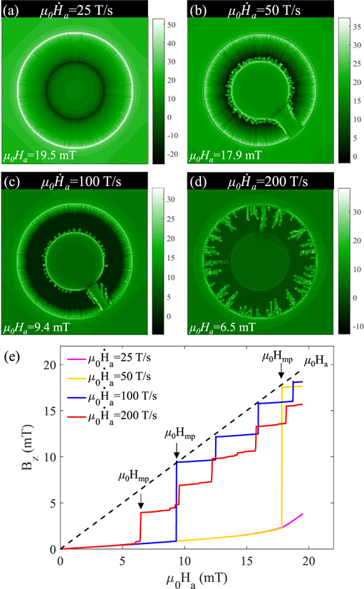
Figure 4. Simulated distributions of Bz
in a single superconducting ring at T0 = 11 K for (a)  T s−1 and μ0
Ha = 19.5 mT; (b)
T s−1 and μ0
Ha = 19.5 mT; (b)  T s−1 and μ0
Hmp = 17.5 T s−1; (c)
T s−1 and μ0
Hmp = 17.5 T s−1; (c)  T s−1 and μ0
Hmp = 9.4 mT; (d)
T s−1 and μ0
Hmp = 9.4 mT; (d)  T s−1 and μ0
Hmp = 6.5 mT. Panel (e) shows the average magnetic field Bz
in the central hole of the ring as a function of the applied field.
T s−1 and μ0
Hmp = 6.5 mT. Panel (e) shows the average magnetic field Bz
in the central hole of the ring as a function of the applied field.
Download figure:
Standard image High-resolution imageAs reported in reference [27], the threshold field μ0
Hth in a ring-shaped superconductor is independent of the rim width. However, μ0
Hth should be dependent on the sample size. Indeed, as shown in figure 5, the threshold field μ0
Hth for rings with the same rim width (the symbols connected by solid lines) and that for rings with a fix Ri (the square symbols connected by a blue dotted line) both decrease with the radius of the ring at different temperatures. For the smallest Ri (Ri = 0.275 mm), there is no flux avalanche triggered in the ring at T0 = 11 K. This can be explained by the fact that the local field at the border of the ring is increased by a large geometric factor  [53–55], leading to a similar increase in the rate of local magnetic field change at the border. This argument leads as to conclude that μ0
Hth should decrease with increasing Ro, as observed in figure 5. This is also consistent with the observations reported in reference [56]. Based on the same reasoning concerning the demagnetization factor, no dependence of μ0
Hth on w (w = Ro − Ri) is to be expected, as indeed shown in figure 5, with symbols connected by a black dotted line.
[53–55], leading to a similar increase in the rate of local magnetic field change at the border. This argument leads as to conclude that μ0
Hth should decrease with increasing Ro, as observed in figure 5. This is also consistent with the observations reported in reference [56]. Based on the same reasoning concerning the demagnetization factor, no dependence of μ0
Hth on w (w = Ro − Ri) is to be expected, as indeed shown in figure 5, with symbols connected by a black dotted line.

Figure 5. The threshold field μ0 Hth for the onset of flux avalanches in superconducting rings of different sizes as a function of the inner radius Ri. The width w = Ro − Ri.
Download figure:
Standard image High-resolution imageIn addition, we also investigate the electrodynamic behavior of a single ring for decreasing applied field by applying a magnetic field of 10.0 mT after cooling down to 11 K, and subsequently reducing the field to −19.6 mT. For μ0 Ha = 10.0 mT, which is larger than μ0 Hth, there is a crossing dendrite in the ring, resulting in a jump of average field Bz in the central hole (see figures 6(a) and (e)). Figure 6(b) presents the flux penetration in the superconducting ring after the applied field is decreased from its maximum value to 0 mT. Bright and dark colors indicate positive high and negative local magnetic field, respectively. The field at the outer edge drops and negative flux (i.e., flux of opposite polarity to the applied field) appears, whereas the field at the inner edge increases. With further decreasing the applied field to −0.3 mT, a clear avalanche of negative flux is triggered retracing along the same path than the initial avalanche, which is consistent with the experimental results reported before [25, 57]. The negative flux outside the ring is injected into the central hole through the dark flux channel, corresponding to the abrupt drop of Bz in figure 6(e). After the first anti-flux perforation event, new events become frequent and several dark multi-branched dendrites appear in the superconducting ring, with more negative flux entering into the central hole and multiple jumps of average magnetic field in the central hole.

Figure 6. Flux penetration on a superconducting ring exposed to a decreasing applied field (a)–(d), and the average magnetic field Bz in the central hole as a function of the applied field (e).
Download figure:
Standard image High-resolution imageWe have shown that magnetic flux can reach the central hole of the single superconducting ring via a flux channel, confirming that the flux jump in the outer hole of concentric rings observed by MOI in figure 2 is caused by the magnetic perforation of the outer ring. Subsequently, a thermomagnetic instability in the inner superconducting ring shown in figure 2 occurs, as in the well-known 'domino effect'. Thus, we will further discuss whether the flux avalanches can continue occurring in the inner superconducting ring.
Figure 7 shows the magnetic field distribution of concentric superconducting rings (with Ri1 = Ro2/4, Ro1 = Ro2/2, Ri2 = 3Ro2/4, Ro2 = 2.2 mm) at different applied fields for T0 = 9 K and  T s−1. The simulated results reproduce the thermomagnetic instability process of the concentric rings observed by MO images presented in figure 2. For the lower applied field, several flux avalanches are triggered in the outer ring, while the inner ring is on a Bean's critical state. As the applied field increases, some flux channels are formed in the outer ring, injecting a large amount of flux into the outer hole as shown in panel (b). This process causes a stepwise increase in the magnetic field in the outer hole as demonstrated in the single ring case. When the field reaches μ0
Ha = 7.5 mT, a thermomagnetic instability of the inner ring is triggered by the increase of the magnetic field in the outer hole. With further increasing applied field to 9.7 mT, the first magnetic perforation event appears in the inner ring accompanied by a jump of the magnetic field in the central hole, while magnetic flux has not fully penetrated the outer ring yet.
T s−1. The simulated results reproduce the thermomagnetic instability process of the concentric rings observed by MO images presented in figure 2. For the lower applied field, several flux avalanches are triggered in the outer ring, while the inner ring is on a Bean's critical state. As the applied field increases, some flux channels are formed in the outer ring, injecting a large amount of flux into the outer hole as shown in panel (b). This process causes a stepwise increase in the magnetic field in the outer hole as demonstrated in the single ring case. When the field reaches μ0
Ha = 7.5 mT, a thermomagnetic instability of the inner ring is triggered by the increase of the magnetic field in the outer hole. With further increasing applied field to 9.7 mT, the first magnetic perforation event appears in the inner ring accompanied by a jump of the magnetic field in the central hole, while magnetic flux has not fully penetrated the outer ring yet.

Figure 7. Simulated distribution of Bz in two concentric superconducting rings cooled to 9 K at different applied fields.
Download figure:
Standard image High-resolution imageIt is important to note that the threshold field of avalanches and the magnetic field captured in the hole strongly depend on temperature as shown in figure 3. We present in figure 8 the influence of T0 on the investigated superconducting concentric rings (Ri1 = Ro2/4, Ro1 = Ro2/2, Ri2 = 3Ro2/4, Ro2 = 2.2 mm) for a ramp rate  T s−1. Panels on the left column show the field landscape just after the first channel in the inner superconducting ring has formed, and panels on the right column correspond to the average fields injected in each hole. For T0 = 7 K (figures 8(a) and (b)), before the first magnetic perforation of the inner ring, there are frequent dendritic avalanches triggered in the concentric rings and several thermal channels formed in the outer ring, which is also confirmed by the quasiperiodic jumps of the average field in the outer hole. With increasing temperature, the number of avalanches before the first magnetic perforation of the inner ring decreases and the jump of average field in the outer hole becomes larger. For the highest temperature T0 = 11 K, the average magnetic field in the outer hole jumps to the value of the applied field μ0
Ha due to the appearance of a crossing dendrite in the outer ring. Interestingly, the threshold field for the onset of magnetic perforation in the inner ring μ0
Hmp-inner does not increase monotonically with temperature, and the crossing dendrite in the inner ring is located near the flux channel of the outer ring, which is marked by the black ellipse. During this rapid process, the average magnetic field in the outer hole first jumps to a certain finite value and then is found to drop slightly. However, this decrease is much smaller than the increase of the average magnetic field in the central hole. These results suggest that the thermomagnetic instability at the inner ring can be triggered by the magnetic perforation in the outer ring, and therefore the mechanism of flux avalanches in this case is more complex.
T s−1. Panels on the left column show the field landscape just after the first channel in the inner superconducting ring has formed, and panels on the right column correspond to the average fields injected in each hole. For T0 = 7 K (figures 8(a) and (b)), before the first magnetic perforation of the inner ring, there are frequent dendritic avalanches triggered in the concentric rings and several thermal channels formed in the outer ring, which is also confirmed by the quasiperiodic jumps of the average field in the outer hole. With increasing temperature, the number of avalanches before the first magnetic perforation of the inner ring decreases and the jump of average field in the outer hole becomes larger. For the highest temperature T0 = 11 K, the average magnetic field in the outer hole jumps to the value of the applied field μ0
Ha due to the appearance of a crossing dendrite in the outer ring. Interestingly, the threshold field for the onset of magnetic perforation in the inner ring μ0
Hmp-inner does not increase monotonically with temperature, and the crossing dendrite in the inner ring is located near the flux channel of the outer ring, which is marked by the black ellipse. During this rapid process, the average magnetic field in the outer hole first jumps to a certain finite value and then is found to drop slightly. However, this decrease is much smaller than the increase of the average magnetic field in the central hole. These results suggest that the thermomagnetic instability at the inner ring can be triggered by the magnetic perforation in the outer ring, and therefore the mechanism of flux avalanches in this case is more complex.

Figure 8. Simulated distribution of Bz in the two concentric superconducting rings after the formation of the first flux channel in the inner ring at three different working temperatures (left column), and the average magnetic field Bz in the outer hole and the central hole as a function of the applied field (right column). The black ellipses indicate magnetic perforations occurring almost simultaneously within the inner and outer rings (domino effect).
Download figure:
Standard image High-resolution imageFigure 9 shows the magnetic field distribution for concentric superconducting rings (with Ri1 = Ro2/4, Ro1 = Ro2/2, Ri2 = 3Ro2/4, Ro2 = 2.2 mm) (a) and (b), and a single ring (with Ri = Ro/4, Ro = 2.2 mm) (c) and (d), for T0 = 10 K and  T s−1. As shown in panel (a), when the applied field reaches 7.1 mT, a flux channel is formed in the outer superconducting ring, through which the magnetic flux is injected into the outer hole and nucleates at multiple positions on the edge of the inner ring. Interestingly, the flux channel in the concentric superconducting rings terminates at the outer hole, and does not extend to the central hole. With further increasing the applied field to 10 mT, there is still only one flux avalanche triggered in the concentric rings as shown in figure 9(b). However, at the same applied field, several flux avalanches occur in the single ring and form two flux channels (figure 9(d)). Surprisingly, the outer hole of the concentric rings shows a stabilization effect, which is also observed in a circular hole [50, 58, 59]. This result indicates that despite the domino effect, the two-concentric-ring structure can not only reduce the scale and frequency of flux avalanches, but also effectively improves the thermomagnetic stability of the inner superconducting films, avoiding flux injection into the central hole of the system.

Figure 9. Simulated distribution of Bz
in two concentric superconducting rings (a) and (b), and in the single superconducting ring (c) and (d) for T0 = 10 K,  T s−1.
Download figure:
Standard image High-resolution imageIn order to clarify the process and the mechanism of this cascade dynamics behavior, in figure 10 we compare the magnetic field distribution of the investigated superconducting rings in figure 8 with that of the single superconducting ring of the same size as the inner ring, as well as calculate the maximum electric field of each of them (panels on the right column). Figures 10(a) and (d) show the magnetic field landscape of concentric rings at μ0
Hmp-outer = 8.6 mT and of single-layer ring at μ0
Hmp = 18.5 mT for the same  and T0 with that in figure 8(e), respectively. For the superconducting concentric rings in this case, once the flux channel is formed in the outer ring, the thermomagnetic instability of the inner ring is activated, and the nucleation loci of the first avalanches in the inner ring is near the channel [see supplemental material 1 at https://stacks.iop.org/NJP/24/083017/mmedia for flux penetration process]. Note that, the threshold field for the onset of avalanches in the inner ring is approximately equal to that of the outer ring (here Hth-outer = Hmp-outer), which is significantly lower than the threshold field of the single-layer of the same size as the inner ring. This observation confirms that the magnetic perforation in the outer ring of the superconducting concentric rings can trigger the flux avalanches in the inner ring. It is well known that with the formation of a magnetic flux channel in a superconducting ring, the average field of the central hole jumps to a certain value. To study the mechanism of the domino effect, we further compare the magnetic field distribution in the outer hole of the concentric rings (figure 10(b)) just after the formation of the flux channels with that outside the single ring (figure 10(e)) before the avalanches nucleate. Remarkably, for the concentric rings, a large amount of magnetic flux is injected into the outer hole through the flux channel, resulting in a rapid increase of local magnetic field in the vicinity, which is much larger than everywhere else in the hole. In contrast to that, for the single-layer superconducting ring, the magnetic field outside the superconductor is equal along the ring. According to the theoretical model developed in reference [60]
  , where T* = |∂ln jc/∂T|−1, the threshold magnetic field for the onset of avalanches can be lowered by increasing the ramp rate of applied field. As a consequence, the fast rate of magnetic field variation in the hole near the flux channel favors the thermomagnetic instability nearby, triggering the flux avalanches in the inner ring.

Figure 10. (a) Flux distribution in two concentric rings (with Ri1 = Ro2/4, Ro1 = Ro2/2, Ri2 = 3Ro2/4, Ro2 = 2.2 mm) after the first magnetic perforation event for T0 = 11 K,  T s−1, and (b) in the outer hole just before the avalanches are triggered in the inner ring. (c) The maximum electric field at the inner ring Emax-inner during the magnetic perforation event. Panels (d)–(f) show the flux penetration, external magnetic field distribution and the maximum electric field of the single superconducting ring of the same size as the inner ring in upper panels.
Download figure:
Standard image High-resolution imageAccording to the linear analysis and numerical results in references [61, 62], avalanches are triggered once the local background electric field exceeds its critical value Ec, and keeps its maximum during the break-down event. This property is illustrated in figure 10(c) where the maximum electric field in the inner ring of concentric rings Emax-inner is shown and compared with that for the single-layer ring Emax (figure 10(f)). The main differences are that the maximum electric field for the inner ring of the concentric rings Emax-inner is lower before it abruptly jumps by almost ten orders of magnitude, and that the thermomagnetic instability of the inner ring lasts longer, which is due to the continuous penetration of the flux through the heated channel of the outer ring. For a single superconducting ring, with the nucleation and growth of avalanches, a large amount of heat is absorbed quickly and dissipated to stabilize the superconductor. However, for the superconducting concentric rings, it takes a longer time for the magnetic flux to flow into the central hole through the flux channel in the outer ring. During this period, the magnetic field distribution in the outer hole is not uniform and the ramp rate is not constant, which triggers the continuous flux avalanches of the inner ring at different points. These results are consistent with our suggestion that the domino effect forms the triggering mechanism of the avalanches in superconducting concentric rings.
Let us now investigate the influence of the gap separating the concentric rings on the flux avalanches by keeping the inner ring width constant and changing its radius. Figure 11 shows the magnetic field distribution and the maximum electric field of the superconducting concentric rings (with Ri1 = 3Ro2/8, Ro1 = 5Ro2/8, Ri2 = 3Ro2/4, Ro2 = 2.2 mm) and those of the single-layer ring of the same size as the inner ring. For the superconducting concentric rings, we can find that the threshold field of the inner ring μ0 Hth-inner determined by the magnetic perforation event of the outer ring slightly increases when the gap is reduced by comparing figures 10(a) and 11(a). On the contrary, the threshold field of the single-layer superconducting ring μ0 Hth decreases from 18.7 mT to 14.7 mT by increasing its outer and inner radius by 0.275 mm. These results seem to indicate that increasing the inner ring radius can increase the stability of the superconducting concentric rings. From panels (c) and (f), one can also see that the break-down event of the inner ring lasts longer than that of the single-layer ring. It is worth emphasizing that for the superconducting concentric rings with a larger inner ring, once a heated channel is formed in the outer ring, the magnetic perforation event in the inner ring is first triggered near the channel (i.e. μ0 Hmp-inner = μ0 Hth-inner) (see supplemental material 2 for magnetic perforation process in the concentric rings). The physical mechanism leading to this domino effect can be understood as follows: as the normal region (avalanche) propagates into the outer ring, supercurrents get compressed toward the inner rim of the outer ring thus generating a local higher magnetic field at the inner rim of the outer ring which in turn triggers the avalanche in the inner ring. As shown in figures 10(b) and 11(b), the local magnetic field at the border of the inner ring near the channel in the outer ring is indeed significantly larger than other region far away. Moreover, the domino effect is stronger when the gap between inner and outer rings is smaller.
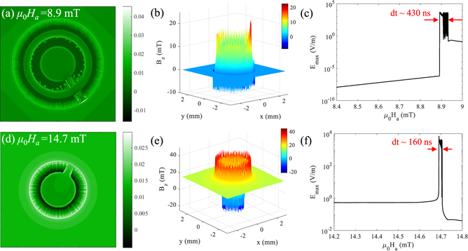
Figure 11. (a) Flux distribution in the concentric rings (with Ri1 = 3Ro2/8, Ro1 = 5Ro2/8, Ri2 = 3Ro2/4, Ro2 = 2.2 mm) after the first magnetic perforation event for T0 = 11 K,  T s−1, and (b) in the outer hole just before the avalanches are triggered in the inner ring. (c) The maximum electric field of the inner ring Emax-inner during this event. Panels (d)–(f) show the flux penetration, external magnetic field distribution and the maximum electric field of the single superconducting ring of the same size as the inner ring in upper panels.
Download figure:
Standard image High-resolution imageThe discussion above suggests that the threshold magnetic fields of the inner ring μ0 Hth-inner and for the magnetic perforation μ0 Hmp-inner depend on the inner/outer radius of the inner ring (i.e. the gap of concentric rings). To further study the triggering condition of the break down event, we present in figure 12 the threshold field for the thermomagnetic instability μ0 Hth-inner as a function of Ro1/Ro2 with Ro2 = 2.2 mm, and we also build up phase diagrams delineating the boundaries of regimes of smooth penetration, flux avalanches (μ0 Hth-inner < μ0 Hmp-inner), and magnetic perforation (μ0 Hth-inner = μ0 Hmp-inner) firstly triggered in the inner ring. The threshold field of the inner ring increases with the outer radius Ro1. Note that in this case, the flux channel is formed in the outer ring after the first thermomagnetic instability event occurs. The inner ring remains stable until the flux is injected into the outer hole through this channel, corresponding to the lower regime in figure 12. The left orange dots correspond to smaller Ro1 for which flux avalanches are triggered in the inner ring without the formation of flux channel connecting the outer hole and the central hole of the superconducting concentric rings. When the outer radius of the inner ring increases to a certain value (Ro1 ⩾ 13Ro2/24), a crossing dendrite is formed in the inner ring after the magnetic perforation event in the outer ring (i.e., μ0 Hmp-inner = μ0 Hth-inner = μ0 Hmp-outer = μ0 Hth-outer), and the flux is injected into the central hole of the superconductor, which is due to the decrease of gap between the rings. This is in accordance with the previous prediction based on figure 11 and the above explanation concerning the domino effect.

Figure 12. The threshold field for the onset of the avalanches in the inner ring μ0
Hth-inner as a function of Ro1/Ro2 with Ro2 = 2.2 mm for T0 = 11 K,  T s−1.
Download figure:
Standard image High-resolution image
4. Conclusions
In summary, we investigate thermomagnetic instabilities in superconducting films with multiply-connected topological structures. MO measurements of MgB2 rings show that flux avalanches can be triggered in the inner ring by a thermomagnetic instability of the adjacent outer ring before the smooth Bean-like magnetic front fully penetrates the outer ring. This domino effect of flux avalanches in multiply-connected topological structures is confirmed and explained by numerical simulations using the thermomagnetic model introduced in reference [36]. We firstly obtain the relationship between the threshold field for the avalanches μ0
Hth and the threshold perforation field μ0
Hmp of a single superconducting ring, by changing the temperature T0 and the ramp rate of the applied field  . For low temperatures or fast ramp rates, μ0
Hth is lower than μ0
Hmp, while for a high T0 or low
. For low temperatures or fast ramp rates, μ0
Hth is lower than μ0
Hmp, while for a high T0 or low  , the flux channel is formed simultaneously with the first avalanche (μ0
Hth = μ0
Hmp). It is worth noting that in addition to the frequency, size, and morphology of the flux avalanches, the average magnetic field injected into the central hole can also be controlled by changing T0 and
, the flux channel is formed simultaneously with the first avalanche (μ0
Hth = μ0
Hmp). It is worth noting that in addition to the frequency, size, and morphology of the flux avalanches, the average magnetic field injected into the central hole can also be controlled by changing T0 and  .
.
For the bi-layer systems consisting of double rings, it is the local current distribution decline near the preceding flux channel in the outer ring that produces a ripple effect on the local magnetic field profile in the gap and at the edge of the inner ring, which ultimately leads to the domino effect of flux avalanches in the concentric rings. Namely, the domino effect of the thermomagnetic instability in such superconducting films with topological structures is not generated by the simple superpositions of flux behavior in the two rings, but depends on the competition between the divergence of the local field at the edge of the inner ring and the shielding by the neighboring ring. Surprisingly, by comparing the magnetic flux behavior of the single superconducting ring with that of the two concentric superconducting rings, it can be found that the multilayer structure can effectively improve the thermomagnetic stability of the internal superconducting films despite the domino effect of flux avalanches in two superconducting rings. By varying the gap between the two concentric superconducting rings, we obtain the threshold field for the onset of the flux avalanches in the inner ring μ0
Hth-inner as a function of Ro1/Ro2 for T0 = 11 K and  T s−1. In this case, μ0
Hth-inner = μ0
Hmp-outer = μ0
Hth-outer. By decreasing the spacing between the concentric rings, the domino effect is reinforced. We obtain the boundaries corresponding to the regimes of smooth penetration, the first flux avalanche triggered in the inner ring without formation of new flux channels (μ0
Hth-inner < μ0
Hmp-inner), and the magnetic perforation event once the thermomagnetic instability is triggered in the inner ring (μ0
Hth-inner = μ0
Hmp-inner), and demonstrate that the domino effect of thermomagnetic instability can be tuned by temperature and the gap width between rings. This study provides a theoretical basis for the design of multilayer superconducting structures, and may also bear some implications to the analysis of electric breakdown in multilayered dielectric heterostructures. The tunable domino effect of thermomagnetic instabilities in such multiply-connected structures helps to understand the physical protection mechanism of complex superconducting heterostructures and the interplay between the neighboring superconducting films forming a topological structure (e.g., SIS cylindrical structure). It could be interesting to further explore the domino effect of thermomagnetic instability in several concentric rings (more than two rings), superconducting/magnetic metamaterials [63] or in multi-layer stacks of superconducting films, as experimentally addressed in reference [31].
T s−1. In this case, μ0
Hth-inner = μ0
Hmp-outer = μ0
Hth-outer. By decreasing the spacing between the concentric rings, the domino effect is reinforced. We obtain the boundaries corresponding to the regimes of smooth penetration, the first flux avalanche triggered in the inner ring without formation of new flux channels (μ0
Hth-inner < μ0
Hmp-inner), and the magnetic perforation event once the thermomagnetic instability is triggered in the inner ring (μ0
Hth-inner = μ0
Hmp-inner), and demonstrate that the domino effect of thermomagnetic instability can be tuned by temperature and the gap width between rings. This study provides a theoretical basis for the design of multilayer superconducting structures, and may also bear some implications to the analysis of electric breakdown in multilayered dielectric heterostructures. The tunable domino effect of thermomagnetic instabilities in such multiply-connected structures helps to understand the physical protection mechanism of complex superconducting heterostructures and the interplay between the neighboring superconducting films forming a topological structure (e.g., SIS cylindrical structure). It could be interesting to further explore the domino effect of thermomagnetic instability in several concentric rings (more than two rings), superconducting/magnetic metamaterials [63] or in multi-layer stacks of superconducting films, as experimentally addressed in reference [31].
Acknowledgments
CX and LJ acknowledge the support by the National Natural Science Foundation of China (Grants Nos. 11972298 and 12011530143). LJ is supported by the China Scholarship Council. The work of AVS was supported by the Fonds de la Recherche Scientifique—FNRS under the grant PDR T.0204.21. SM acknowledges support from FRS-FNRS (research fellowship ASP).
Data availability statement
All data that support the findings of this study are included within the article (and any supplementary files).