


Abstract
We examine the dynamics of superconducting vortices with twofold anisotropic interaction potentials driven over random pinning, and compare the behavior under drives applied along the hard and the soft anisotropy directions. As the driving force increases, the number of topological defects reaches a maximum near the depinning threshold, and then decreases as the vortices form one-dimensional (1D) chains. This coincides with a transition from a pinned nematic to a moving smectic aligned with the soft anisotropy direction. The system is generally more ordered when the drive is applied along the soft direction of the anisotropy. For driving along the hard direction, there is a critical value of the twofold anisotropy above which the system remains aligned with the soft direction. Hysteretic behavior appears upon cycling the driving force, with 1D vortex chains persisting during the decreasing leg below the threshold for chain formation for increasing drive. More anisotropic systems have a greater amount of structural disorder in the moving state. For lower anisotropy, the system forms a moving smectic-A state, while at higher anisotropy, a moving nematic state appears instead.
Export citation and abstract BibTeX RIS
1. Introduction
A wide range of systems can be described effectively as an assembly of particles interacting with each other and with quenched disorder, leading to the appearance of depinning and multiple sliding phases [1, 2]. Such systems include vortices in type-II superconductors [2, 3], colloidal particles [4–6], active matter [7, 8], magnetic skyrmions [9, 10], pattern forming systems [11, 12], and sliding Wigner crystals [13, 14]. In each case there is a threshold for motion or a depinning transition above which the particles enter a disordered or fluctuating state containing numerous topological defects [2, 15]. One of the most studied systems of this type is vortices in type-II superconductors, which can exhibit dynamical transitions at higher drives into ordered moving phases such as a moving crystal [16], anisotropic crystal [17], or moving smectic [18–21]. These transitions are associated with changes in the structure factor [17–21], the number and orientation of topological defects [18, 20, 21], and the noise characteristics [21–25]. In a two-dimensional (2D) system driven over random disorder, the fluctuations experienced by the particles due to their motion are anisotropic, leading to the formation of a moving smectic state [19]. Beyond superconducting vortices, moving smectics have been studied in other 2D systems driven over quenched disorder including Wigner crystals [14] and frictional systems [26].
In most of the above mentioned systems, the particle–particle interactions are isotropic, and in the absence of quenched disorder an isotropic crystal appears. For example, in the case of type-II superconductors with isotropic repulsion, the vortices form a triangular lattice [3]. There are, however, many examples of particle-like systems that have twofold anisotropic interactions, including colloidal particles in tilted magnetic fields [27, 28], dusty plasmas [29], electron liquid crystal states [30–32], skyrmions [33–35], and superconducting vortices [36–43]. Anisotropic vortex–vortex interactions can arise from anisotropy in the material or nematicity in the substrate, or it can be induced by a tilted field in uniaxial superconductors. Theoretical work on vortex liquid crystal systems with twofold anisotropy showed that these systems can form smectic-A states and exhibit two step melting transitions [39, 41]. Magnetic skyrmions have many similarities to superconducting vortices and typically form a triangular lattice under isotropic conditions [44, 45]. 2D anisotropic skyrmions can produce what are called skyrmion liquid crystals with smectic [35] or more specifically smectic-A ordering [46]. Far less is known about the behavior of driven states of anisotropic crystals in quenched disorder, such as what dynamical ordering transitions appear and what differences arise when the driving is applied along different anisotropy directions.
In this work we study the dynamics of superconducting vortices with a twofold anisotropy potential in the presence of pinning. Here driving forces are applied along the hard and soft directions of the vortex–vortex interaction as the magnitudes of the anisotropy and the pinning density are varied. The results may be applicable to members of the family of iron-based superconductors, where a strong electronic in-plane ansiotropy and elliptical vortices are observed [47]. However, while some studies of the anisotropic dynamics have been reported [48], achieving single domain samples and eliminating vortex pinning to twin boundaries remains a challenge. In addition to superconducting vortices, our results should also be relevant to the wider class of assemblies of particles with twofold anisotropic interactions moving over quenched disorder.
2. Methods
In previous computational modeling of vortices as point particles, the vortices had a pairwise isotropic repulsive potential that is proportional to the zeroth order Bessel function, U(r) = K0(r) [49], causing the vortices to form a triangular ground state in the absence of quenched disorder. Some attempts were made to introduce effects of anisotropy by multiplying the force components of an isotropic interaction potential by different factors along orthogonal directions [41]. Although this approach produced anisotropic diffusion, smectic ordering appeared only for very large differences in the multiplication prefactors, making this an unrealistic representation of anisotropic systems.
Recently, point particle models incorporating twofold, four-fold, and six-fold anisotropic interactions have been considered in the context of triangular to square and other vortex lattice rotational transitions [50, 51]. This work used a vortex–vortex interaction potential with na anisotropy axes,

where r = |ri
− rj
| is the distance between vortices at positions ri
and rj
and the angle between the vortices with respect to the x-axis is θ = tan−1(ry
/rx
) with r = ri
− rj
,  and
and  . Here Av
is the isotropic vortex interaction strength that is used as a normalization parameter, as discussed below. The magnitude of the anisotropic contribution to the vortex interaction is given by Ka. The interaction potential in equation (1) produces a more complex interaction, including non-radial forces, between the particles than simple multiplicative factors, and hence provides a better realization of anisotropic systems.
. Here Av
is the isotropic vortex interaction strength that is used as a normalization parameter, as discussed below. The magnitude of the anisotropic contribution to the vortex interaction is given by Ka. The interaction potential in equation (1) produces a more complex interaction, including non-radial forces, between the particles than simple multiplicative factors, and hence provides a better realization of anisotropic systems.
In this work a twofold anisotropy (na = 2) is studied. Specifically, we examine the dynamics of systems with different anisotropy strengths driven over quenched disorder. Figure 1 illustrates the equipotential lines for the twofold anisotropic vortex potential with K2 = 0, 0.5, 1.0 and 1.5. For K2 = 0, the interaction is isotropic and the vortices form a triangular lattice with no preferred orientation. As the anisotropy increases, the potentials become more elongated, implying that the vortex–vortex interaction forces are strongest along the x-direction and weaker along the y-direction. Increasing or decreasing the value of K2 changes the magnitude of the energy potential experienced by each vortex, which is equivalent to a change in the effective vortex density. This may be quantified by an effective magnetic field that is proportional to the 2D integral of the interaction potential:

Using K2 = 0 and Av = 2.0 as a reference, potential effects arising from a density difference are eliminated by setting Av = 4/(2 + K2) for each individual simulation, such that all have the same value of Beff.

Figure 1. Equipotential lines for the vortex–vortex interaction in equation (1) for different values of the anisotropy parameter K2 = 0.0 (a), 0.5 (b), 1.0 (c) and 1.5 (d). The pinch points along the y-axis lead to the formation of vortex chain states.
Download figure:
Standard image High-resolution imageMolecular dynamics simulations were carried out for a 2D system of size L × L with L = 72λ, where λ is the London penetration depth, with periodic boundary conditions imposed in both the x- and y-directions. For all simulations the number of vortices was Nv = 2280 corresponding to a vortex density ρv = Nv/L2 = 0.4398/λ2. The dynamics of vortex i are governed by the following overdamped equation of motion:

Here η is the damping constant which is set to unity. The vortex–vortex interaction force is Fvv = −∇(U) = (−∂U/∂x, −∂U/∂y). With a twofold anisotropy and ϕa = 0, the force is


Each vortex also experiences forces  from the substrate, which is modeled as Np parabolic pinning traps placed in random but non-overlapping positions. Each pinning site has a radius rp and can exert a maximum force of Fp. The vortex–pin interaction is directed toward the center of the pinning site and is given by
  . The individual pinning parameters are kept fixed at rp = 0.5λ and Fp = 0.5, which allow a single pinning site to capture at most one vortex. Pinning densities ρp = Np/L2 ranging from zero to 0.4825/λ2 were studied. Thermal forces are modeled by Langevin kicks
  with the properties ⟨FT⟩ = 0.0 and
  where kB is the Boltzmann constant.
The initial vortex positions are obtained using simulated annealing. Starting from a high temperature FT = 4.0 where the vortices are rapidly diffusing in a liquid state, the system is gradually cooled to zero temperature in decrements of ΔFT = −0.05 every 104 simulation time steps. After the initial annealing, a driving force FD is applied in either the x- or y-direction. Here x is the hard direction of the anisotropy along which the vortices are more repulsive, and y is the soft direction. The drive starts at FD = 0.0, increasing by ΔFD = 0.05 every 104 simulation time steps up to a maximum value of 1.5. The drive is then reduced back to zero at the same rate.
The structural properties of the vortex system are analyzed in real space using a Voronoi polygon construction. This yields the local coordination number zi
of each vortex, which is used to compute the fractions 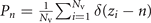 for n = 5, 6, and 7. The most relevant parameter is the fraction of defects Pd = 1 − P6, which provides a measure of the disorder of the system. All reported values of Pd were obtained by averaging the results of 10 simulation runs. The structure factor,
 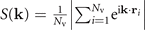 , provides a complementary measure of the order in reciprocal space.
3. Results
Figure 2(a) shows the fraction of topological defects Pd versus driving force FD for a system with K2 = 0.55 and ρp = 0.4825/λ2. Initially the system is in a disordered configuration after the annealing process with a large fraction, Pd = 0.43, of vortices that are not sixfold coordinated. As FD increases, a depinning transition occurs near FD = 0.25 that coincides with a maximum in the defect density of Pd = 0.45 for y-direction driving and Pd = 0.48 for x-direction driving. Generally, the depinning threshold is slightly higher for driving in the x-direction due to the relatively larger average spacing between the vortices in that direction induced by the anisotropy. Above depinning, Pd decreases rapidly with increasing FD and approaches Pd = 0.05 for FD > 1.0. The minimum value of Pd is similar for driving in either direction at this value of K2. As the drive is decreased from its maximum value of FD = 1.5, the system returns to a disordered state for both directions. Increasing the twofold anisotropy to K2 = 1.45 while keeping the pinning density constant leads to a distinction between drives along the x- and y-directions, as shown in figure 2(b). Here, there is a clear difference in the defect density, with y-direction driving producing much lower values of Pd, indicating that the system is better ordered when the drive is aligned with the soft anisotropy direction corresponding to the natural smectic orientation of the system. For driving in the x and y-directions, the defect fraction reaches a minimum value of Pd = 0.25 and 0.14 respectively Again, the system disorders as the drive is reduced, reaching nearly identical values of Pd ≈ 0.34 at the pinning transition.

Figure 2. Fraction of topological defects Pd versus driving force FD in a system with ρp = 0.4825/λ2 for drives along the x-direction (blue) and the y-direction (red). (a) K2 = 0.55. (b) K2 = 1.45.
Download figure:
Standard image High-resolution imageTo complement the characterization in terms of the overall defect fraction in figure 2, the corresponding structural properties in both real and reciprocal space were examined. Figure 3(a) shows a Voronoi construction of a portion of the system from figure 2(a) for K2 = 0.55, ρp = 0.4825/λ2, and zero drive, where there are a large number of dislocations indicated by non-sixfold coordinated vortices. The corresponding structure factor S(k) in figure 3(d) contains a set of broad peaks along the vertical direction for kx = 0, indicative of weak nematic ordering with one-dimensional (1D) chains of vortices aligned in the y-direction. The anisotropy of the vortex–vortex interaction is evident from the elliptical diffuse intensity, since an isotropic interaction would give rise to a circle. Figures 3(b) and (e) show the same system with a drive of FD = 1.5 applied along the x-direction. Here, only a small number of vertically aligned dislocations are present. The corresponding structure factor is still anisotropic but now has sharp peaks in the y-direction indicative of a smectic phase. A similar moving smectic phase is seen in figures 3(c) and (f) when a drive of FD = 1.5 is applied along the y-direction. In contrast to earlier work for isotropic systems where the smectic phase is always oriented along the direction of the drive [18, 20, 21], we observe an alignment along the soft anisotropy direction for K2 > 0.2 regardless of the direction of the drive.

Figure 3. Structural properties of the vortex system in figure 2(a) with K2 = 0.55 and ρp = 0.4825/λ2: (a)–(c) Voronoi constructions of a portion of the sample showing sixfold (white), fivefold (red), and sevenfold (blue) coordinated vortices. (d)–(f) Corresponding structure factors S(k) calculated for the entire system. (a) and (d) Pinned weak nematic state at zero drive. (b) and (e) Smectic state for a drive FD = 1.5 along the x-direction. (c) and (f) Smectic state for FD = 1.5 along the y-direction.
Download figure:
Standard image High-resolution imageFigure 4 summarizes the main structural properties observed for the higher anisotropy of K2 = 1.45. A pinned nematic state still appears at zero drive as shown in figures 4(a) and (d), with numerous defects indicated by five and sevenfold coordinated vortices and broad peaks on the vertical axis in the structure factor for kx = 0 together with diffuse lines on the left and right. Figures 4(b) and (e) show the same system for driving in the y-direction with FD = 0.75. The vortices are more ordered, with fewer defects in the Voronoi construction and sharper peaks in S(k), and the system has formed a moving nematic. In figures 4(c) and (f), for an increased drive of FD = 1.5 in the y-direction, the number of defects has diminished further and the peaks in S(k) are still sharper. The vortices are now organized in a series of non-overlapping 1D chains indicating smectic ordering.

Figure 4. Structural properties of the vortex system in figure 2(b) with K2 = 1.45 and ρp = 0.4825/λ2: (a)–(c) Voronoi constructions of a portion of the sample showing sixfold (white), fivefold (red), and sevenfold (blue) coordinated vortices. (d)–(f) Corresponding structure factors S(k) calculated for the entire system. (a) and (d) Pinned nematic state at zero drive. (b) and (e) Nematic state for a drive FD = 0.75 along the y-direction. (c) and (f) Smectic state when the drive is increased to FD = 1.5.
Download figure:
Standard image High-resolution imageThe difference between nematic and smectic phases are illustrated in more detail in figure 5. Figure 5(a) shows a smaller region of the Voronoi construction from figure 4(a), and figure 5(b) contains a corresponding schematic of the vortex configuration. Here the system forms chains that begin, end and intertwine inside the sample, forming a nematic structure. In figure 5(c) we show a small region of the Voronoi construction from figure 4(c) for y-direction driving with FD = 1.5 where the system forms a smectic state and the 1D chains do not overlap. Figure 5(d) shows a schematic of the vortex structure in this state, which is known as smectic-A in liquid crystal systems [46]. This is similar to the phase proposed for vortex liquid crystals with anisotropic potentials [39]. Here there are no breaks in the 1D chains. Individual chains can contain different numbers of vortices, producing dislocations that are aligned in the y-direction. The lack of order perpendicular to the chains is evident from the structure factor in figure 4(f), which has diffuse vertical lines, rather than peaks, for kx ≠ 0. Changing the drive to be along the x-direction for the K2 = 1.45 system produces a very similar result, although the nematic phase persists up to higher values of FD. Finally, we note that the transition between nematic and smectic states is gradual, and near the cross-over the classification can be ambiguous as seen in figures 4(b) and (e).

Figure 5. Nematic and smectic ordering for the system with K2 = 1.45 and ρp = 0.4825/λ2. (a) Expanded view of the Voronoi construction from figure 4(a) with zero drive. (b) A schematic of the vortex locations in panel (a), showing a nematic arrangement with 1D chains of vortices that break and merge. (c) Voronoi construction from figure 4(c) with a drive of FD = 1.5 along the y-direction. (d) A schematic of the vortex locations in panel (c), showing a smectic-A arrangement with vortices forming 1D chains that do not cross.
Download figure:
Standard image High-resolution imageTo characterize the system across the entire range of anisotropies and drives, one can consider the variation in the defect density during the cycle FD = 0 → 1.5 → 0. Figure 6(a) and (b) show the minimum and maximum values of Pd as a function of K2 in samples with ρp = 0.4825/λ2 for drives along the x-direction and the y-direction, respectively. The maximum falls at the depinning threshold and the minimum is at the highest drive of FD = 1.5. Consider first the results in figure 6(a) for driving in the y-direction. For low K2 < 0.8, at depinning there is a nematic state with Pd ≈ 0.45. The vortices order into a moving smectic phase at higher drives with the defect density reaching minimum values in the range Pd = 0.03–0.07. For K2 > 0.9, the system is less defected at the depinning transition but contains more defects in the driven reordered states. As the anisotropy increases, it becomes more difficult to destroy the chains of vortices at depinning, giving a lower density of defects at the depinning transition; however, it becomes easier for the chains to slide past one another at higher drives, creating a larger number of more persistent dislocations in the driven phase. Turning now to the results in figure 6(b) for driving in the x-direction, one again observes a smaller number of defects at depinning with increasing K2 due to the greater durability of the chains, but a greater number of defects appear at the maximum drive due to the preservation within the chains of the defects that were present at low drives. Furthermore, there is a peak in the minimum number of defects near K2 = 0.2, where the smectic undergoes a transition from alignment in the x-direction to alignment in the y-direction. This reorientation transition arises due to the competition between the twofold anisotropy, which favors an alignment along the soft direction of the vortex–vortex interaction, and the motion of the vortices, which favors an alignment along the direction of the drive [18, 20, 21]. Thus for K2 < 0.2, the system forms a moving smectic aligned in the x-direction, while for 0.2 < K2 < 0.8, the system forms a moving smectic aligned in the y-direction. When K2 > 0.9, a moving nematic aligned in the y-direction appears at higher drives.

Figure 6. Minimum (orange) and maximum (purple) values of Pd during the FD = 0 → 1.5 → 0 cycle plotted versus K2 in samples with ρp = 0.4825/λ2. (a) Driving in the y-direction. (b) Driving in the x-direction.
Download figure:
Standard image High-resolution imageFigure 7 shows the Voronoi construction and structure factor for the system at the critical value K2 = 0.2 for a drive of FD = 1.5 in the x-direction. Here, the system does not form a nematic or smectic aligned in the y-direction, but instead adopts a polycrystalline ordering with domain boundaries decorated by strings of defects. One of the domains is oriented along the x-direction, as evident from the structure factor that has two prominent peaks on the horizontal axis for ky = 0. For even smaller values of K2, the system exhibits a strong smectic alignment along the x-direction for driving in the x-direction.

Figure 7. (a) Voronoi construction of a portion of the sample showing sixfold (white), fivefold (red), and sevenfold (blue) coordinated vortices for the system in figure 6(a) with ρp = 0.4825/λ2 and K2 = 0.2 under driving in the x-direction at FD = 1.5. (b) The corresponding structure factor shows a partial alignment in the x-direction.
Download figure:
Standard image High-resolution imageThe fraction of defects shows a hysteretic behavior for the cycle FD = 0 → 1.5 → 0. This is quantified by numerically integrating the magnitude of the difference in the defect fraction for increasing  and decreasing
  drive
drive  , indicated by the shaded areas in figure 8. Figure 9 shows the hysteresis for two different values of the pinning density which display qualitatively similar features. First, the magnitude of H increases with pinning density, with the largest values occurring for lower values of K2 where Pd varies over a greater range and a nearly perfect lattice at high drives remains more robust against pinning forces as FD is decreased. Second, for driving in the x-direction, there is a peak in H near K2 = 0.2 corresponding to the smectic x-direction to y-direction realignment transition. Third, a crossover is observed at K2 ≈ 1.0 [figure 9(a)] and K2 ≈ 0.9 [figure 9(b)] for the higher and lower pinning density respectively. Below the crossover, the hysteresis is largest for driving in the x-direction, while above the crossover, the situation is reversed.

Figure 8. Determination of the hysteresis measure H defined in the text. Values of Pd are shown for increasing  and decreasing
  drive along the x-direction in a system with K2 = 0.1 and ρp = 0.4825/λ2.
Download figure:
Standard image High-resolution image
Figure 9. Hysteresis versus anisotropy for the different drive directions and two different pinning densities: (a) ρp = 0.4825/λ2 and (b) ρp = 0.096 45/λ2.
Download figure:
Standard image High-resolution imageA broader survey of pinning densities up to ρp = 0.4825/λ2 and different directions of the drive is given in figure 10, which shows heat maps of the minimum value of Pd (i.e., for FD = 1.5) as a function of K2 versus ρp. For driving in the x-direction, the light blue line at K2 ≈ 0.2 in figure 10(a) indicates the switching of the smectic from x-direction to y-direction alignment. The critical value of K2 at which this transition occurs increases with increasing ρp, since a greater anisotropy is required to form chains aligned in the soft anisotropy direction that are also robust against being driven over a higher density of pinning sites. For K2 > 1.0 and ρp > 0.1, the amount of disorder in the system increases dramatically and a nematic state replaces the smectic state. For driving in the y-direction, shown in figure 10(b), the smectic structures formed by the vortices are always aligned in the y-direction. Furthermore, the system generally remains in a smectic state even as the number of defects increases for K2 > 1.0 and ρp > 0.19.

Figure 10. Heat map of the minimum fraction of topological defects Pd at FD = 1.5 as a function of K2 and ρp. (a) Driving in the x-direction. The light blue line in the lower region of the plot indicates the transition in the smectic alignment from x-direction to y-direction. (b) Driving in the y-direction.
Download figure:
Standard image High-resolution image
4. Summary
We have examined the driven dynamics of vortices with twofold anisotropic interaction potentials driven over quenched disorder. In general, the pinned states have nematic ordering and the driven states form moving smectic-A phases. A more ordered smectic state containing fewer dislocations appears for driving along the soft anisotropy direction compared with driving along the hard anisotropy direction. Cycling the drive leads to a hysteresis in the dynamics. Specifically, once the smectic state has formed, it can persist down to lower drives than those at which it appeared on the initial application. We also find that as the anisotropy increases, the system is generally less ordered in the high drive states since dislocations have a lower formation energy. We map out the dynamic phase diagram as a function of anisotropy and pinning density, characterized by the defect density and the structure factor. Our results should be general to the broader class of driven systems with twofold anisotropy driven over random disorder, which includes electronic liquid crystals, colloidal particles, and magnetic skyrmions.
Acknowledgments
We are grateful to D Minogue, M W Olszewski and D Spulber for assistance with the molecular dynamics simulations and analysis. This research was supported in part by the Notre Dame Center for Research Computing. Work at the University of Notre Dame (EJR, MRE: MD simulations, data analysis) was supported by the US Department of Energy, Office of Basic Energy Sciences, under Award No. DE-SC0005051. Part of this work (CR, CJOR: code development) was carried out under support by the US Department of Energy through the Los Alamos National Laboratory. Los Alamos National Laboratory is operated by Triad National Security, LLC, for the National Nuclear Security Administration of the US Department of Energy (Contract No. 892333218NCA000001).
Data availability statement
All data that support the findings of this study are included within the article (and any supplementary files).