


Abstract
Study of the formation and evolution of large scale, ordered structures is an enduring theme in science. Generation, evolution and control of large sized magnetic domains are challenging tasks, given the complex nature of competing interactions in a magnetic system. Here, we demonstrate large scale non-coplanar ordering of spins, driven by picosecond, megagauss magnetic pulses derived from a high intensity, femtosecond laser. Our studies on a specially designed yttrium iron garnet (YIG) dielectric/metal film sandwich target, show the creation of complex, large, concentric, elliptical shaped magnetic domains which resemble the layered shell structure of an onion. The largest shell has a major axis over hundreds of micrometers, in stark contrast to sub micrometer scale polygonal, striped or bubble shaped magnetic domains in magnetic materials, or large dumbbell shaped domains produced in magnetic films irradiated with accelerator based relativistic electron beams. Micromagnetic simulations show that the giant magnetic field pulses create ultrafast terahertz (THz) spin waves and a snapshot of these fast-propagating spin waves is stored as the layered onion shell shaped domains in the YIG film. Typically, information transport via spin waves in magnonic devices occurs in the gigahertz regime, where devices are susceptible to thermal disturbances at room temperature. Our intense laser light pulse—YIG sandwich target combination, paves the way for room temperature table-top THz spin wave devices, operating just above or in the range of the thermal noise floor. This dissipation-less device offers ultrafast control of spin information over distances of few hundreds of microns.
Export citation and abstract BibTeX RIS

Original content from this work may be used under the terms of the Creative Commons Attribution 4.0 licence. Any further distribution of this work must maintain attribution to the author(s) and the title of the work, journal citation and DOI.
1. Introduction
Conventional condensed matter systems display a diverse variety of static magnetization configurations like Bloch or Neel domain walls, magnetic vortices [1, 2], stripe domains [3] and skyrmions [4]. These domains arise out of a competition between different magnetic exchange and magnetostatic energies [5, 6]. Over the past few decades, a great deal of effort has gone into using light for probing different aspects of condensed matter physics [7–12]. Effects of light interacting with magnetism have been primarily studied with low intensity (I ∼ 105–106 W cm−2) femtosecond (fs) lasers [7–10] for exploring demagnetization processes occurring on time scales of a few picosecond (ps) [10, 13–15]. Recently, optical coupling of angular momentum of light with spins in magnetizable media has been shown to create micron-sized domains on fs timescales [8, 16–18]. The use of high intensity fs laser pulses (I ∼ 1014–1018 W cm−2) for such studies has however not been attempted so far. This may be attributed to the apprehension that the enormous energy scale associated with such excitation would overwhelm the spin–spin interaction energy scale and the thermal damage induced by such intense laser pulse would obliterate the possibility of seeing any ordered spin configuration. Indeed, direct irradiation with such intense pulses typically ablates the material creating a high temperature plasma. However, interaction of an intense fs laser pulse with the plasma is interesting as it is known to produce giant megagauss (MG) magnetic field pulses of ps duration [19–24]. It is therefore extremely interesting to study the response of magnetic materials to such intense magnetic pulses. In this paper, we demonstrate the creation of novel, unusual spin structures created by this magnetic pulse, with an innovative target design and careful control of experimental conditions.
We study the response of yttrium iron garnet (YIG) films subjected to MG magnetic field pulses produced by the interaction of 1017–1018 W cm−2 intensity, 30 fs laser pulses with a solid target. YIG is a well-known ferrimagnetic insulator film with very low damping, which has become an attractive material for studying magnon dynamics in recent times [25–27] (magnons are quasi particles associated with spin waves). Low damping of magnetization dynamics coupled with large magnon diffusion lengths reaching several microns [28], make YIG an important material for applications in magnonics [29–31], spin caloritronics [32–34] and magnon-based microwave applications [35, 36]. A careful target design is however, crucial for eliminating the ablative degradation of YIG due to laser induced ionization and subsequent heating. We therefore implement a novel sandwich target geometry of metal (Al)-dielectric–YIG film (figure 1(A)), where the laser irradiates the top Al layer, leaving the lower YIG layer unaffected by laser induced damage. Magneto-optical microscopy (MOM) of the YIG samples exposed to the laser generated giant magnetic field shows the creation of novel, large, concentric, elliptically shaped magnetic domains extending up to a few hundreds of microns from the projected irradiation location. The shape resembles layered shells of an onion. Furthermore, we see that the local magnetic field direction flips up and down periodically across these elliptical domain structures and its magnitude also has a periodic variation with distance from the center of the irradiation. Micromagnetic simulation of a YIG film subjected to MG field pulse shows the excitation of ripples of spin waves traveling across the low damping YIG film, a few ps after the pulse. The spin waves cause the moments to gradually rotate out of the film plane periodically resulting in the observed behavior of the measured local field. These fast spin waves diffuse up to a few hundreds of microns in the YIG film from the projected laser irradiation site, giving rise to a non-coplanar spin configuration, which in turn might give rise to an additional, Dzyloshinskii–Moriya (DM) type interaction contribution to the magnetic energy of YIG. We propose this interaction together with pinning effects, results in the spin waves getting stored as the layered onion shell like magnetic domain structure.
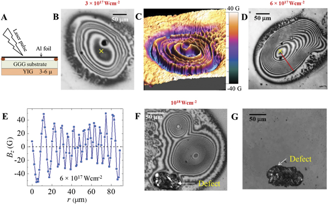
Figure 1. MOM images of laser irradiated YIG films. (A) Schematic shows the incidence of the fs laser pulse on a 16 μm thick Al film suspended 100 μm above the GGG substrate, on the lower side of which is the YIG film. A dielectric layer of thickness ∼200 μm composed of air and the GGG substrate, exists between the Al and the YIG film. (B) The × mark is the estimated projected location of the laser spot on the YIG film. (B), (D) and (F) MOM images of concentric elliptical magnetic domains generated in YIG film after irradiation at laser intensities (I) of (B) 3 × 10¹⁷ W cm−2, (D) 6 × 10¹⁷ W cm−2 and (F) 1018 W cm−2, respectively. (C) Color coded three-dimensional map of the Bz (x, y) distribution in the elliptical domains of (B). Colors represent the magnitude of the Bz values as shown in the color-bar scale. (E) Bz profile [viz, Bz (r)] measured along the red line in (D), showing periodic oscillations in Bz as one traverses the concentric rings of the elliptical domain pattern. The maximum amplitude of the oscillating Bz (r) is ±40 G. (F) Twin domain patterns generated in YIG with a single laser pulse at 1018 W cm−2. The smaller (upper) domain structure is more circular than the one below. Also seen is a defect in the YIG film, which was present before irradiation. (G) MOM image of the same region as in (F), imaged after 10 days of laser irradiation, with the black defect as the identifier. Here we see layered onion shell like magnetic domain patterns have disappeared.
Download figure:
Standard image High-resolution image2. Experimental setup
Each target (figure 1(A)) consists of a 16 μm thick Al film suspended over a gallium gadolinium garnet (GGG) substrate in a sandwich configuration. The lower side of the GGG substrate has a bismuth-doped YIG film grown on it [37, 38]. In the GGG substrate—YIG film, the YIG has high Verdet constant making it a Faraday active component. We use single pulses of 30 fs duration (p-polarized, center wavelength 800 nm) having 20 μm beam diameter to irradiate identical points at different locations on the Al layer at an angle of incidence of 45°. The laser intensities used are between 3 × 10¹⁷ to 1 × 10¹⁸ W cm−2 [details of setup in supplementary information [39], section 1, figure S1(a)]. The YIG film is isolated from the optical field of the intense laser as well as the heating effects it generates. The sandwich configuration provides a two-level protection to the YIG film.
Firstly, it eliminates laser induced ionization of the YIG film and the resulting thermal heat load that could lead to direct damage of the film, since the intense laser pulse ablates the sacrificial Al layer which takes away these deleterious effects. Secondly, the magnetic YIG layer has additional shielding from the heating effects provided by the intervening 200 μm thick dielectric air gap and the GGG layer present between Al and YIG film layers. Without the sandwich target configuration, the laser pulse damages the YIG film due to ablation, which makes it impossible to image any domain like features produced in the film. It may also be worth noting that the thin aluminum film used in our sandwich configuration gets ablated and acts as a sacrificial layer at the irradiated site. For each laser pulse irradiation, the target is moved to a fresh spot.
The YIG film was devoid of any micron sized magnetic domains prior to irradiation. As late as 4 days after irradiation, the irradiated region is imaged using a high sensitivity MOM [MOM setup details in supplementary information [39], section I, figure S1(b) and reference [24]]. The magneto-optical intensity is  , where Bz
is the component of local field perpendicular to the surface. The Bz
(x, y) distribution is determined from the MOM intensity distribution by suitable calibration [24] (the x and y axes are in the film plane while z axis is perpendicular to the film). Since the GGG substrate is not a Faraday-active material, the YIG film solely contributes to the magneto-optical intensity. Therefore, we are indeed measuring the local field distribution of YIG devoid of any substrate contribution.
, where Bz
is the component of local field perpendicular to the surface. The Bz
(x, y) distribution is determined from the MOM intensity distribution by suitable calibration [24] (the x and y axes are in the film plane while z axis is perpendicular to the film). Since the GGG substrate is not a Faraday-active material, the YIG film solely contributes to the magneto-optical intensity. Therefore, we are indeed measuring the local field distribution of YIG devoid of any substrate contribution.
3. Results and discussion
The MOM images in figures 1(B), (D) and (F) show the creation of magnetic domain patterns recorded in the YIG film layer, after irradiation by single pulses of laser intensities of 3 × 10¹⁷ W cm−2, 6 × 10¹⁷ W cm−2, and 1 × 10¹⁸ W cm−2, respectively. All images show the formation of concentric black and white elliptical shaped onion shell-like magnetic domains in the YIG film. The overall sizes of the elliptic domain patterns at different laser intensities are comparable and do not scale with laser intensity. The number of concentric rings, however, increases with increasing laser intensity. The full extent of the concentric domain patterns is at least an order of magnitude larger than the laser beam diameter of 20 μm. The peaks and troughs in the color-coded three-dimensional view of Bz (x, y) in figure 1(C), correspond to periodic modulation of local field Bz across the bright and dark regions of the pattern in figure 1(B). A comparison of the concentric domains in figure 1(B) with figure 1(D) shows the number of concentric rings increasing with intensity (I) of the laser. Furthermore, figure 1(F) shows that at a high intensity of 1018 W cm−2 there is a large elliptical domain pattern with concentric rings, and an adjacent satellite concentric domain with a relatively lower eccentricity. There is an interesting reversal in the dark–bright sequence from center of the pattern in the satellite fringes compared to the main pattern. Figure 1(G) shows an MOM image of the same region of the YIG film as in figure 1(F), but recorded 10 days after irradiation. Due to experimental constraints the first MOM imaging of the irradiated film was performed 4 days after the laser irradiation. In this set of experiments the concentric ring like domain patterns were imaged on the film. After this the samples were stored away in a magnetic field free environment. After 10 days when the same region of the film was imaged, we found the patterns had disappeared. Note that image of the defect in the YIG film layer of figure 1(F) is retained in figure 1(G), however the magneto-optical contrast of the domain patterns has diminished such that the patterns are no longer discernible. Due to the thermally activated decay of remanent magnetization which happens in any magnetized film, it is likely that the pattern in our YIG film gradually disappears as the difference in local magnetization values of the bright and dark rings in pattern gradually sensitivity of MOM imaging technique (∼0.5 G) at room T. Once this happens, one is unable to distinguish between the bright and dark rings. Thus, disappearance of the observed patterns are magnetic domains and not permanent or irreversible features, viz, they are not related to laser induced heating. The magnetized regions are generated by the action of the MG magnetic pulse created by the laser. The following sections explore the origin of this quasi-stable domain feature observed in YIG film.
It is well established in intense laser–solid interaction studies that a high intensity, p-polarized fs laser pulse incident on a target at a non-normal angle sets up electron waves in the generated plasma, which grow to large amplitude before breaking. This breaking unleashes a giant current pulse (∼mega-ampere) that travels normally into the planar target and the entire process is known as resonance absorption (RA) [23, 40]. The current pulse is due to RA generated single or multiple collimated relativistic electron jets [41]. These jets generate giant, azimuthal magnetic fields (Bϕ ), having peak pulse height of few hundreds MG with typical pulse widths of a few ps [19–22] [details on RA in supplementary information [39], section III, figure S3].
To explore the effect of these RA generated giant magnetic field pulses on YIG films, we model the temporal evolution of in-plane local magnetization  in the YIG film under the influence of a magnetic field pulse (figure 2(A)) through the Landau–Lifshitz–Gilbert (LLG) equation using the MuMax software [42, 43] (see supplementary information [39], section II for simulation details). We simulate YIG films with dimensions 150 × 150 μm2 and thickness 3 μm. The material parameters used in the calculations are as follows: Ms = 1.4 × 10⁵ A m−1, exchange constant A = 3.6 × 10⁻¹² J m−1, α = 0.0005 and anisotropy constant K = 610 J m−3. The film is discretized cells with grid lengths of 1 μm × 1 μm × 1 μm. At the vertex of each cell a magnetic moment is placed. It may be noted that due to the computationally intensive nature of the simulations, we simulate a structure smaller than that in the experiment. We have however checked that the main features of the simulations remain the same irrespective of the film size used for simulations. Also, we were interested in capturing the long wavelength magnetic modes which maybe excited on the YIG films by the application of giant magnetic field pulses, rather than the excitation of small (submicron) wavelength modes. The initial magnetic configuration of YIG in the simulations is in-plane. We have used magnetic field pulse of pulse height varying between 0.07 MG (half-maxima) and 350 MG, pulse width σ = 10 μm and pulse time, t = 1 ps.


Figure 2. Simulation of YIG films using MuMax. (A) Schematic of the magnetic precession of the in-plane moments of magnetic film due to the MG magnetic field. (B) and (C) Simulation of YIG films showing ripples in the magnetic moment configurations are generated in the YIG film with magnetic pulses, B0 = 7 and 35 MG, recorded at time, t = 0.5 s. The ripples spread out as a function of increasing time. (D) Plot of  across the red solid line in (D) shows periodic modulations of the magnetic moment configuration in the film at t = 0.5 ps.
Download figure:
Standard image High-resolution imageThe first term on the right in equation (1) is the torque on  due to the effective magnetic field (
 = field component in azimuthal direction (
 ) + demagnetizing field (
 ) + anisotropy field (
 )), where γ is the gyromagnetic ratio. The in-plane azimuthal field pulse (figure 2(A)) is
  where
where  is the azimuthal unit vector in film plane. The second term is a damping term with damping constant α. The
  pulse first causes
  to flip out of the film plane by an angle θ0 due to a torque,
  . For YIG a large Bϕ
pulse of 7.5 MG (discussed subsequently) gives a θ0 = (γBϕ
)Δt = 10.5° in a pulse duration Δt ∼ 0.5 ps (YIG has γ = 28 G HzT−1 [44]. The flipped
. For YIG a large Bϕ
pulse of 7.5 MG (discussed subsequently) gives a θ0 = (γBϕ
)Δt = 10.5° in a pulse duration Δt ∼ 0.5 ps (YIG has γ = 28 G HzT−1 [44]. The flipped  generates a demagnetization field (
 ∼ −M sin θ0
 ,
,  is ⊥ to film) (figure 2(A)) around which
  precesses. At this stage, spin waves are excited in the magnetic material. Simultaneously, damping (second term in equation (1)) comes into play, leading to the decay of the waves as the precessing
  gradually loses energy and falls toward the film plane (blue dashed trajectory in figure 2(A)), until its energy is just lower than the anisotropy energy barrier (∝Ku sin(ψ), ψ-angle between
  and
and  ). Note that the anisotropy energy is minimum for parallel (ψ = 0) or antiparallel (ψ = π) orientations. Here
  performs a damped precession around
  before falling back into the film plane, with
  oriented either along or opposite to
  . Finally, minimizing the free energy leads to domains with in-plane
  , where the in-plane
  orientation periodically flips by π across the domains.
For our simulations, the azimuthal magnetic field distribution experienced by the YIG film is approximated using an expression similar to that for the field distribution at positions located away from the relativistic electron bunch [45], viz,  for r > σ, where, r is the distance from the projected center of laser irradiation on the YIG film and σ is the diameter of region around irradiation center within which there are the RA generated current jet (s). We use σ as the diameter of the irradiating laser beam. In the region r < σ, we use a uniform Bϕ
= B0. The temporal behavior of the pulse is ξ(t − tp) = 1 for 0 ⩽ t ⩽ tp = 1 ps and ξ(t − tp) = 0 for t > tp. In the above expression,
for r > σ, where, r is the distance from the projected center of laser irradiation on the YIG film and σ is the diameter of region around irradiation center within which there are the RA generated current jet (s). We use σ as the diameter of the irradiating laser beam. In the region r < σ, we use a uniform Bϕ
= B0. The temporal behavior of the pulse is ξ(t − tp) = 1 for 0 ⩽ t ⩽ tp = 1 ps and ξ(t − tp) = 0 for t > tp. In the above expression,  , is the field [45] present outside the boundary of radius σ/2, where n is the number of electrons in the current jet and e is the electron charge. Figures 2(B) and (C) show results of the LLG simulations in YIG with a time independent damping constant α, at time (t) = 0.5 ps after the application of magnetic field pulse with peak field B0 of 7 MG and 35 MG respectively. Note that B0 = 7.5 MG (n = 1.2 × 10¹²) and 35 MG (n = 5.6 × 10¹²) correspond to an order of magnitude larger than the number of electrons in our intense laser pulse generated electron jet compared to those in the relativistic electron bunch at SLAC. The Zeeman energy associated with our giant Bϕ
pulse in YIG is ∼14 296 MJ m−3 (supplementary information [39], section V), is sufficiently large to completely overwhelm the low magnetic anisotropy energy of YIG (Ku = 6.10 × 10² J m−3). Figures 2(B) and (C) show that the Bϕ
pulse excites circular spin wave ripples in the YIG film around
, is the field [45] present outside the boundary of radius σ/2, where n is the number of electrons in the current jet and e is the electron charge. Figures 2(B) and (C) show results of the LLG simulations in YIG with a time independent damping constant α, at time (t) = 0.5 ps after the application of magnetic field pulse with peak field B0 of 7 MG and 35 MG respectively. Note that B0 = 7.5 MG (n = 1.2 × 10¹²) and 35 MG (n = 5.6 × 10¹²) correspond to an order of magnitude larger than the number of electrons in our intense laser pulse generated electron jet compared to those in the relativistic electron bunch at SLAC. The Zeeman energy associated with our giant Bϕ
pulse in YIG is ∼14 296 MJ m−3 (supplementary information [39], section V), is sufficiently large to completely overwhelm the low magnetic anisotropy energy of YIG (Ku = 6.10 × 10² J m−3). Figures 2(B) and (C) show that the Bϕ
pulse excites circular spin wave ripples in the YIG film around  (center of the pulse). With increasing time, the ripples spread out across the film [see movie as in reference [46]], until they reach the film edge within 1 ns. At long times (∼100 ms), a complex rectangular multi-domain configuration is stabilized in the YIG film, which is unlike the domains we have recorded in figure 1 (movie at reference [46], and supplementary information [39], section VI, figure S5). We do not observe any dependence of the simulation results on the lateral film dimensions as long as they are larger than the ripple wavelength. The rippling feature seen in the simulations closely resembles our observed elliptical layered onion shell domain structure of figure 1 (see figures 2(B) and (C) and supplementary information [39], figure S2). Further similarity between the simulated features and our experiment is seen in figure 2(D), where we calculate the orientation (θ) of local
  in the film w.r.t. the film plane viz,
  , measured along the radial direction drawn as a red line in figure 2(C). The contrast modulations seen in figures 2(B) and (C) clearly correspond to the periodic flipping of z component of
  , which is evident from the θ(r) behavior in figure 2(D). The periodic flipping of
  , viz, the behavior of θ(r) in figure 2(D) is similar to the behavior of Bz
(r) in figure 1(E).
, viz, the behavior of θ(r) in figure 2(D) is similar to the behavior of Bz
(r) in figure 1(E).
Figures 2(B) and (C) show that at 0.5 ps, the diameter of the outer edges of the rippling structure are comparable for B0 = 7.5 MG and 35 MG. The number of rings inside the concentric circular structures increases with B0. These observations from the simulations match with that of figure 1 (also see supplementary information [39], figure S2) while the overall size of the domain is independent of the laser intensity the number of concentric rings (N) increases with intensity (figures 1(B) and (F)). The simulations show that increase in N is related to increase in the pulse peak field B0 (figures 2(B) and (C)). By comparing the number of rings (N), determined as a function of laser intensity (I) (experiments, like figures 1(B), (D) and (F)) as a function of B0 (simulations, like in figures 2(B) and (C)), an empirical relation between B0 and I is obtained (details in supplementary information [39], figure S4). Our experiments reveal that for I ⩽ 1017 W cm−2, no elliptical domains form. Using the empirical relation, this intensity corresponds to a peak field of B0 ∼ 0.1 MG. Our simulations also confirm that there are no discernible magnetized ripples excited in YIG below 0.1 MG field.
We now turn to the explanation of the two adjacent patterns in figure 1(F). A quick look tells us that the magnetic field polarity is reversed for the satellite domain structure, as the bright–dark sequence from the center of the pattern is reversed in the satellite fringes compared to the main pattern in figure 1(F). Thus, the periodic Bz
variation from the center of the pattern is phase shifted by π, which is due to the initial field pulse due to the laser irradiation at the center of these two concentric patterns being of opposite polarity. This opposite field polarity feature is understood to be caused by the electron jet which is pulled back into the target at the interfaces, a well-known feature known as refluxing in intense laser–solid interactions. This phenomenon, also known as the 'fountain effect' is caused by the large electric and magnetic fields present at the interface [47]. The extent of electron travel along the surface before re-entry into the target is well derived by the fields reported in [47] and in fact opens up the exciting possibility that the present magnetic mapping using YIG films may serve as a very useful diagnostic for fast electron refluxing. Simulating equation (1) using a general form of Bϕ
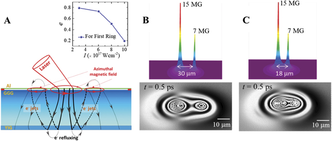
with multi-peaks [19–23], viz,  with i = 1 to 2, we observe in figure 3(B) two well-separated rippling structures (after 0.5 ps), which are similar to the features in figure 1(F). By reducing the spacing between the field pulses down to 18 μm we observe (figure 3(C)) a single rippling structure produced by the overlap of two spin wave ripples. The resulting ripple is not circular but elliptical. Similar to we observe in our experiments (figure 1). The multi-peaked field structure may result from multiple closely spaced e-jets generated during RA process, as explained above and shown in the schematic of figure 3(A). The inset of figure 3(A) shows the behavior of eccentricity (e), calculated for the first ring in the experimentally measured domain structures formed in YIG as a function of laser intensity (I). It is evident that
e
varies smoothly as a function of I. With increase in laser energy, the shape of the structure changes smoothly from elliptical to round shape. We believe this dependence is related to the shape of the magnetic field distribution generated around the laser irradiation site which depends on the laser energy E. The laser energy controls the extent and nature of bunching of the electron jets generated by the beam, which in turn determine the shape of the magnetic distribution. The absence of any random changes in the shape of the domain over multiple experiments with different laser energies shows that the domain shape is hardly affected by any stochasticity in the multiple electron jet generation processes. The average shape of the domains is controlled by the energy of the laser pulse. The small distortions in shape may arise from microscopic imperfections present in the film, e.g. intrinsic defects and pinning sites in YIG.
with i = 1 to 2, we observe in figure 3(B) two well-separated rippling structures (after 0.5 ps), which are similar to the features in figure 1(F). By reducing the spacing between the field pulses down to 18 μm we observe (figure 3(C)) a single rippling structure produced by the overlap of two spin wave ripples. The resulting ripple is not circular but elliptical. Similar to we observe in our experiments (figure 1). The multi-peaked field structure may result from multiple closely spaced e-jets generated during RA process, as explained above and shown in the schematic of figure 3(A). The inset of figure 3(A) shows the behavior of eccentricity (e), calculated for the first ring in the experimentally measured domain structures formed in YIG as a function of laser intensity (I). It is evident that
e
varies smoothly as a function of I. With increase in laser energy, the shape of the structure changes smoothly from elliptical to round shape. We believe this dependence is related to the shape of the magnetic field distribution generated around the laser irradiation site which depends on the laser energy E. The laser energy controls the extent and nature of bunching of the electron jets generated by the beam, which in turn determine the shape of the magnetic distribution. The absence of any random changes in the shape of the domain over multiple experiments with different laser energies shows that the domain shape is hardly affected by any stochasticity in the multiple electron jet generation processes. The average shape of the domains is controlled by the energy of the laser pulse. The small distortions in shape may arise from microscopic imperfections present in the film, e.g. intrinsic defects and pinning sites in YIG.
Figure 3. Correlation of simulations with experiments. (A) fs laser hits the Al film and creates multiple electron (e) jets. These e-jets moving at relativistic speeds carrying mega-amps of current generate magnetic field around it (Bϕ ). The current direction due to the electron jets are in both upwards and downward direction. The opposite electron jets are jets pulled back into the target, due to refluxing. These electron jets give rise to MG azimuthal magnetic fields with both polarities, experienced by the YIG layer. The inset shows the behavior of eccentricity (e), calculated for the first ring in the experimentally measured domain structures formed in YIG as a function of laser intensity (I). (B) and (C) Simulations done on the YIG film using two sharply peaked magnetic field pulses having B0 of 15 MG and 7 MG, separated by 30 μm and 18 μm. The ripples created in the YIG film are well separated when the separation between the field pulses is significant while the two ripples merge into an elliptical shaped ripple when the pulses are closer to each other. The ripple patterns shown are obtained by stopping the simulation at t = 0.5 ps.
Download figure:
Standard image High-resolution image
From the simulations, we determine the phase velocity (vp) of the spin waves generated by the giant field pulse, as the ratio of the distance covered by the crest of a ripple to the time taken. The vp turns out to be in the range of ∼107 ms−1 which is four orders of magnitude greater than the typical limit of domain wall velocity (∼1000 ms−1) reported for YIG films [48]. Note that vp is not related to physical motion of domain walls. Using vp and the measured wavelength of the ripple (λ) excited at different energies, we obtain  for our spin wave to be in the range of ∼30–100 THz (depending on the laser intensity). Some earlier measurements suggested that spin waves with frequencies ωm ∼ few THz [49, 50] can be excited in YIG films. We show that one to two order of magnitude higher THz frequency spin waves can be excited using our intense laser and the novel metal/dielectric/YIG film sandwich target combination.
The close match between our simulations and experiments in YIG demonstrates a unique effect, viz, excitation of fast propagating spin waves excited in the YIG film. Furthermore, the YIG effectively captures a snapshot of the propagating spin wave. What is the mechanism by which the spin wave transforms into a static magnetic domain pattern? To get a glimpse into the answer, we determine from our simulations the amount of non-co-planar  configuration is generated at the domain site i in YIG by the giant field pulse viz, we calculate the average value of
  within a region of 10 μm × 10 μm inside the simulated ripple of magnetic disturbance in figure 2. The average value of
  per unit area associated with each ripple turns out to be ∼0.9 μm−2 compared to 0 μm−2 prior to the pulse. To understand the transformation of magnons (dynamic phenomenon) to static domains, we have to consider the conditions in the highly non-equilibrium system created when the YIG film is exposed to intense laser irradiation. Under these conditions the strong magnetic field pulse generated by the laser excites fast propagating magnonic waves which diffuse up to large distances in the YIG film. We propose that, the magnonic waves help in the excitation of a significantly large number of non collinear spin configurations in the film. We estimated from simulations that non-coplanarity in spin configuration increases in the region with the magnonic wave. Within a region of 10 μm × 10 μm inside the ripple, the estimated average value of non-coplanar component of magnetization (
 ) is ∼0.9 μm−2 compared to 0 μm−2 in the film prior to the irradiation. Consider a quantity,
  is a measure of the net non-coplanar spin component excited in the YIG film by the laser pulse (the integration is over the volume of the ripples in the film). Due to the excitation of the magnonic waves propagating out to large distances in the film, the function Δ×(t) sharply increases within a few ps after the laser irradiation and decreases later. Although the DM interaction strength (d) in YIG is weak (∼16 μJ m−2), it is not negligible [51]. The DM interaction energy density is of the order of d
 . Therefore, due to the increase in Δ×(t), the net DMI energy in the YIG film will also significantly rise under the conditions prevalent during the excitation of the magnonic wave. Typically, it is well known that DM interaction produces static chiral magnetic domain patterns [4–6]. Thus, during the intense laser irradiation, a sudden, large increase in Δ×(t) and the consequent significant rise in the DM interaction energy in YIG helps to stabilize the large concentric-shaped domain patterns containing non-collinear spin configurations. We propose it is this DM interaction that is responsible for the transformation into the static domain patterns. The fast-moving spin wave modes excited in the YIG by the giant field pulse, very rapidly carry away significant amounts of energy from the precessing spins present in the spin-wave. This results in fast damping of the precessing spins. Thus, as precession rapidly damps out, the spins relax to form stable domain structures. Consequently, the domain formation from the temporary spin configuration excited by the wave will be governed by the competition between DM interaction (above) excited by the spin waves and the weak magnetic anisotropy of YIG. Note that YIG has a magnetic anisotropy Ku = 6.1 × 10⁻⁴ MJ m−3 which is nearly two orders smaller compared to other strong magnetic anisotropy materials (supplementary information [39], table S1). As Ku is small, the weak anisotropy field in YIG results in spatially isotropic circular shaped domain compared to dumbbell shaped domain pattern in high Ku films used in the SLAC study [52, 53]. We therefore propose that the dominant DM interaction plays an important role in stabilizing the chiral shaped domain (figure 1) in our YIG film, through the above process. In fact, based on our preliminary analysis, it is plausible that our onion shell concentric domain configuration has a topologically protected nature, suggesting that DM interactions play a role in their formation (see supplementary information [39], section VII, figure S6). We would like to mention that pinning in the YIG film also participates in process of stabilizing these domains. It is possible that pinning results in the irregular shape of the outermost ring seen in figure 1. It may be worthwhile in future to explore simulations to study the role of the above DM interaction and pinning effects in stabilizing the excited spin waves into the observed onion shell concentric domain configuration, with the possibility of chirality.
There appears to be only one other group that has studied the influence of ultra-strong, ultrashort magnetic pulses on magnetic films [52, 53] but there are crucial and important differences between our study and theirs. They subjected films of high Ku (Ku ∼ 0.1 MJ m−3) viz, high  to (a) magnetic field pulses of the order of a few tens of Tesla and also (b) electric (E) fields ∼109 V m−1. These fields were generated by irradiating the film directly with relativistic electron (e−) bunches with 28 and 40 GeV energies at SLAC. The presence of a strong anisotropy field in the magnetic film material resulted in anisotropic dumbbell like domain pattern [52, 53]. The in-plane
  across adjacent domains in the dumbbell pattern were aligned anti-parallel. The distinct spatial symmetry of our domain shapes, viz, layered onion shell structure, is in stark contrast to the anisotropic dumbbell shaped domains found in the SLAC studies. Another distinguishing feature of our domains is this—as one moves along a line cutting across the domains,
  periodically twists out of the plane leading in turn to a periodic modulation of local Bz
(figure 1(E)) while in the SLAC study,
periodically twists out of the plane leading in turn to a periodic modulation of local Bz
(figure 1(E)) while in the SLAC study,  always remains in-plane. These contrasting results suggest significant differences in the physical processes leading to the distinct domain shapes seen in our experiments. We would like to suggest that our YIG film has properties that are completely different from those used in the SLAC study. YIG has a damping constant, α, which is nearly two orders of magnitude smaller than that of the material used in the SLAC study (so is YIG's magnetic anisotropy, for a comparison see supplementary information [39], table S1). The low α value makes it feasible for the excitation and sustenance of the spin waves in YIG by the magnetic-pulse. It is also important to mention the differences in the methods used to generate the field pulses in both cases. Our intense laser generated field pulses are essentially magnetic while both
  and
and  pulses are generated by the relativistic e-bunches in the SLAC experiments [52, 53]. The electron beam in the SLAC study traverses the film and causes film damage, while such a deleterious effect is completely avoided in our study. Lastly, our Bϕ
pulse is stronger by at least an order of magnitude [19, 20] (∼100 T) compared to that in the SLAC study (∼10 T).
pulses are generated by the relativistic e-bunches in the SLAC experiments [52, 53]. The electron beam in the SLAC study traverses the film and causes film damage, while such a deleterious effect is completely avoided in our study. Lastly, our Bϕ
pulse is stronger by at least an order of magnitude [19, 20] (∼100 T) compared to that in the SLAC study (∼10 T).
From the layered onion shell domains recorded in YIG film we show that fs laser pulse excites THz spin waves in YIG with diffusion lengths up to hundreds of microns. This result has potential applications for spin wave-based devices. In recent times, the generation, control and manipulation of spin waves have emerged as an important research area [54, 55] as they can be utilized in dissipation-less transfer of information across a device. In conventional electron transport-based devices, increasing electrical resistance with miniaturization significantly increases the dissipation losses, thereby limiting the processing speed of these devices. However, in magnonic devices, spin waves with frequencies, ωm < 10 GHz, are launched via spin Hall effect or spin torque effect using an electrical current [28, 35]. The electrical contacts in these magnonic devices for current injection result in unavoidable Joule heating dissipation at the contacts. These devices also need to be operated at low temperatures as the spin waves are susceptible to thermal noise, since for ωm < 10 GHz the ℏωm ≪ kB T (=0.025 eV at 300 K). However, the spin waves excited in our metal/dielectric/YIG sandwich using indirect irradiation of YIG with the intense laser pulses completely eliminate the need for using electric currents for exciting the waves and hence limit Joule heating dissipation. Furthermore, the fast-propagating spin waves with long diffusion lengths reaching up to hundreds of microns have frequencies that can be varied between 10 to 100 THz by varying the laser intensity. Hence magnonic devices employing our method are suitable for room temperature operation, as the energy of spin waves excited in YIG by intense laser pulse is far above the thermal noise floor (as for ωm ∼ 10 to 100 THz, ℏωm ⩾ kB T). We re-emphasize that our design for launching spin waves has multiple advantages compared to doing the same with an accelerator based relativistic electron beam [52, 53]. We have a much more compact table top design, less complexity in operation and the strength of the field pulses and pulse durations can be conveniently controlled by varying the laser intensity, the target design and the interaction geometries. Some potential opto-magnetic applications include, use of the fast-propagating magnonic waves as dissipation-less carriers of logic information for fast data processing. Our present sandwich target configuration allows for single shots of the laser at one spatial location of the target. We are exploring improvements in the design to enable multiple laser pulse irradiation at the same spatial location.
4. Conclusions
We have demonstrated novel, macroscopic, concentric elliptical onion shell-like magnetic domains created in YIG film via giant magnetic field pulses of ps duration, generated from fs, intense laser pulses. Spin waves excited in the YIG film by the field pulse generate non-coplanar spin configurations in the YIG film which give rise to DM interactions which were initially weak in the YIG film. These interactions together with pinning in these films cause the spin waves to stabilize into surprisingly long-lived elliptical domain patterns. Our innovative metal/dielectric/YIG structure irradiated with intense laser pulse offers a new way to excite ultrafast spin waves with frequency in the few tens to hundreds THz range with large diffusion lengths. These high frequency spin waves are undisturbed by thermal fluctuations. Hence our tabletop route offers a new way for developing a dissipation less high frequency magnonic devices which are capable of operating at room temperature.
Acknowledgments
SSB would like to acknowledge the funding support from IIT Kanpur and the Department of Science and Technology, Government of India, New Delhi. GRK acknowledges partial support from the Science and Engineering Board (SERB), Government of India, New Delhi through a J C Bose National Fellowship (JBR/2020/000039). GRK acknowledges the late Predhiman K Kaw for stimulating discussions.
Data availability statement
The data that support the findings of this study are available upon reasonable request from the authors.