


Abstract
The coherent control of electron beams and ultrafast electron wave packet dynamics have attracted significant attention in electron microscopy as well as in atomic physics. In order to unify the conceptual pictures developed in both fields, we demonstrate the generation and manipulation of tailored electron orbital angular momentum (OAM) superposition states either by employing customized holographic diffraction masks in a transmission electron microscope or by atomic multiphoton ionization utilizing pulse-shaper generated carrier-envelope phase stable bichromatic ultrashort laser pulses. Both techniques follow similar physical mechanisms based on Fourier synthesis of quantum mechanical superposition states allowing the preparation of a broad set of electron states with uncommon symmetries. We describe both approaches in a unified picture based on an advanced spatial andspectral double slit and point out important analogies. In addition, we analyze the topological charge and discuss the control mechanisms of the free-electron OAM superposition states. Their generation and manipulation by phase tailoring in transmission electron microscopy and atomic multiphoton ionization is illustrated on a 7-fold rotationally symmetric electron density distribution.
Export citation and abstract BibTeX RIS

Original content from this work may be used under the terms of the Creative Commons Attribution 4.0 licence. Any further distribution of this work must maintain attribution to the author(s) and the title of the work, journal citation and DOI.
1. Introduction
Spatially coherent electron probes have developed into a versatile tool for exploring the quantum nature of matter on the atomic scale [1]. Especially electron orbital angular momentum (OAM) beams with tailored symmetries and topologies [2–4] opened up a new degree of freedom in quantum control scenarios and may provide selective access to additional material properties. Recently, these beams have enabled quantized OAM transfer to atoms in electron-energy loss spectroscopy (EELS) [5, 6] and were proposed for the characterization of chiral crystal symmetries in electron diffraction [7]. Inducing magnetic transitions in atoms using OAM electron beams may provide a tool to probe magnetic states of matter on the nanoscale [8]. Furthermore, electron beams with unusual topology exhibit intricate field-interaction effects, including free-electron Landau states [9].
Optical OAM beams [10–12] already found a variety of applications ranging from fundamental physics [13–16] to optical tweezers [17, 18] and spanners [19]. In contrast to the micrometer-sized foci of optical OAM beams, for OAM electron beams the orbital angular momentum plays a more significant role in electron–matter interaction, due to their nanometer-sized foci overlaping with atomic-scale quantum systems [20, 21]. Therefore, electron OAM states, characterized by a phase singularity, a helical phase front and a non-vanishing topological charge ℓ [2–4], are the subject of current research.
In recent years, several experimental techniques for the generation of high-quality OAM electron beams were developed for transmission electron microscopy (TEM), including the application of diffraction holograms [5, 22] and phase masks [23–27], as well as by using the quasi-monopole magnetic field of a thin magnetic needle [28]. Furthermore, inelastic [29–37] and elastic [38–40] electron-light scattering have been demonstrated to facilitate a detailed control of the phase structure of electron beams.
In ultrafast and attosecond spectroscopy of atoms, coherent control of photoemitted electrons was utilized to obtain a detailed picture of light-driven strong-field ionization channels, including perturbative [41] and non-perturbative multiphoton ionization (MPI) [42] and tunneling processes [43–45]. Polarization-tailored bichromatic (nω: mω) fields [46–51] have been established as powerful tools in coherent quantum control [52] and were shown to address optically controlled quantum interferences between pre-defined electron wave functions [49, 53–55]. Governed by quantum mechanical dipole selection rules (σ±-transitions), OAM superposition states with uncommon symmetry properties have been generated [54, 56]. By combining photoionization using pulse-shaper generated polarization-tailored laser pulses with photoelectron tomography, unprecedented control of the 3D photoelectron angular distributions has been demonstrated.
In this contribution, we demonstrate that a broad set of electron states can be generated by quantum interference using holographic electron diffraction in TEM and MPI. Experimental results for the preparation of OAM superposition states with both approaches are presented and analyzed in a unified theoretical description. Control of the phase structure of the OAM superposition states, as well as their symmetry and topological character are discussed.
2. Experiment
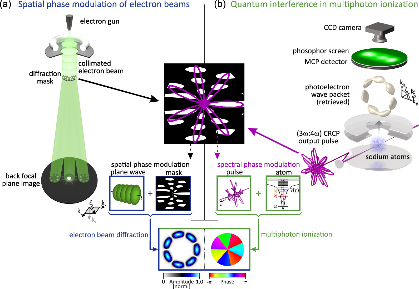
We investigate two complementary experimental approaches to generate and manipulate tailored OAM superposition electron states, utilizing spatial phase modulation (SPM) in a transmission electron microscope and multipath quantum interference from bichromatic MPI of atoms. A sketch of the experimental setups, highlighting the analogies of both approaches, is shown in figure 1. The electron distributions of the generated states are detected in momentum-space, either in the far-field in the case of the SPM approach or by velocity map imaging (VMI) photoelectron spectroscopy.

Figure 1. Schematic experimental setups. (a) In the SPM approach, a tailored holographic mask is illuminated by a spatially coherent electron beam in a transmission electron microscope. OAM superposition electron states are formed via far-field diffraction. (b) In the MPI approach, the interaction of a pulse-shaper generated ultrashort polarization-tailored supercontinuum with sodium atoms simultaneously drives two pre-selected ionization channels, leading to the generation of a superposition photoelectron state, which is detected in a VMI spectrometer. Both approaches result in electron states with a 7-fold rotationally symmetric electron density.
Download figure:
Standard image High-resolution imageIn general, OAM superposition states, also termed mixed-OAM states, are composed of two single OAM states with topological charges ℓ1 = −n and ℓ2 = m. In a two-dimensional space of polar momentum coordinates (k, ξ), such OAM superposition states are generally described by:

in which
G(k) is a real-valued radially depended
function and β =
β0eiγ
a
complex-valued superposition amplitude, with
 controlling the relative amplitude of both components and γ
their relative phase. In the following, we consider
β0 = 1, a discussion of the azimuthal
probability currents for superpositions with β0
≠ 1 is given in section 3.
The superposition phase γ is controlled by experimental
means, either by the construction of the mask in SPM, or by the optical phases of
the bichromatic field in MPI, as explained in section 3.2.
controlling the relative amplitude of both components and γ
their relative phase. In the following, we consider
β0 = 1, a discussion of the azimuthal
probability currents for superpositions with β0
≠ 1 is given in section 3.
The superposition phase γ is controlled by experimental
means, either by the construction of the mask in SPM, or by the optical phases of
the bichromatic field in MPI, as explained in section 3.2.
For a single OAM state eimξ with integer m ≠ 0, the electron density shows a doughnut-shaped, azimuthally symmetric distribution [57, 58]. The interference in the OAM superposition state described by equation (1) leads to a reduced azimuthal symmetry. In contrast to the electron wave function Ψ, which belongs to the C1 point group, the probability density of the superposition state is obtained as

yielding an (n + m)-fold rotational symmetry [54, 58].
2.1. Spatial phase modulation of electron beams
For the generation of OAM electron beams in a TEM, we utilize a hologram-based
approach [5, 59–61] (experimental sketch in figure 2(a)), in which a diffraction mask
 is derived from the superposition of an apertured plane
wave
is derived from the superposition of an apertured plane
wave
 and a real-space target electron wave
function
and a real-space target electron wave
function

yielding the real-valued mask function

Here, circR (r) is the circular aperture function with radius R and κSPM a relative phase. By illuminating this mask with an electron plane wave, the mask's diffraction pattern Γ(kx , ky ) (cf figure 1(a)) is formed in the far-field:

As shown
in appendix  consists of a central component and two side lobes at
distances ±k0 in
kx
−direction.
Following the general principle of holography, the Fourier transform of the
real-space target state,
consists of a central component and two side lobes at
distances ±k0 in
kx
−direction.
Following the general principle of holography, the Fourier transform of the
real-space target state,
 , and its complex conjugate are forming the side lobes.
For a given reciprocal distance k∓ =
keq around the center of the first diffraction
order of the reference wave, the phase behavior of the Fourier-transformed
target wave follows equation (1). Moreover, for
k∓ ≈
keq the probability density of the superposition
state can be approximated by
, and its complex conjugate are forming the side lobes.
For a given reciprocal distance k∓ =
keq around the center of the first diffraction
order of the reference wave, the phase behavior of the Fourier-transformed
target wave follows equation (1). Moreover, for
k∓ ≈
keq the probability density of the superposition
state can be approximated by

in which
GSPM(k∓) is a
function governed by the choice of the circular aperture radius,
k∓ and
ξ∓ denote shifted momentum
coordinates and
 (cf appendix

Figure 2. Concepts for the generation of OAM superposition electron states utilizing SPM and MPI. (a) In the SPM approach, a holographic mask (middle) is generated by mixing a plane-wave reference state with a target electron state, which is chosen here as a superposition of two OAM states (bottom). The calculated electron intensity and phase distribution in the far-field (top) reveal a mixed-OAM state with 7-fold rotational symmetry within the first diffraction orders (real-space mask diameter: 3.7 μm, scale bar: 10 μm−1). (b) A tailored CRCP bichromatic laser field (bottom) addresses predefined quantum pathways in the multiphoton excitation of sodium atoms (middle) and leads to a mixed-OAM photoelectron state composed of two torus-shaped single OAM states (top). The interference of the two quantum paths can be interpreted as a spectral double slit, as opposed to the advanced spatial double slit in (a).
Download figure:
Standard image High-resolution imageExperimentally, we utilized a binarized version of the calculated mask
 (binarization threshold at half intensity maximum),
which we fabricated by focused ion beam milling of a 30 nm gold thin film on a
silicon nitride membrane (15 nm thickness). In the cut-through sections of the
mask, the electron wave is transmitted. Non-cut sections result in wave
components scattered by large angles and are subsequently blocked by apertures.
For the hologram, we chose k0 = 15
μm−1 and an aperture diameter of
3.7 μm. The mask is illuminated by an electron beam with
large coherence length (coherence length:
(binarization threshold at half intensity maximum),
which we fabricated by focused ion beam milling of a 30 nm gold thin film on a
silicon nitride membrane (15 nm thickness). In the cut-through sections of the
mask, the electron wave is transmitted. Non-cut sections result in wave
components scattered by large angles and are subsequently blocked by apertures.
For the hologram, we chose k0 = 15
μm−1 and an aperture diameter of
3.7 μm. The mask is illuminated by an electron beam with
large coherence length (coherence length:
 1.74 μm, angular spread:
2α = 1.44 μrad) formed in
a transmission electron microscope (JEOL JEM-2100F, 200 kV
acceleration voltage). Using the post-specimen imaging lens system, the
diffraction pattern of the mask is projected on the detector
(GATAN Orius SC600 charge-coupled device (CCD) camera;
effective camera length: 300 m), giving access to the spatial profile of the
probability density of the electron state (cf figure 1).
1.74 μm, angular spread:
2α = 1.44 μrad) formed in
a transmission electron microscope (JEOL JEM-2100F, 200 kV
acceleration voltage). Using the post-specimen imaging lens system, the
diffraction pattern of the mask is projected on the detector
(GATAN Orius SC600 charge-coupled device (CCD) camera;
effective camera length: 300 m), giving access to the spatial profile of the
probability density of the electron state (cf figure 1).
2.2. Quantum interference in multiphoton ionization
In the ultrafast bichromatic MPI approach, sodium atoms are ionized with polarization-tailored bichromatic laser pulses [51] to induce interference of pre-selected electron wave functions [54, 62–64]. Here, we consider atomic MPI (with Np photons) from the sodium 3s ground state (figure 2(b)) using counter-rotating circularly polarized (CRCP) bichromatic propeller-type pulses (shown in figures 2 and 3) to generate OAM superposition states, yielding the photoemitted electron wave function in spherical momentum coordinates (k, ξ, ϑ) as

using

with the
radial part
 of the continuum wave function (determined by the
Npth order spectrum of the laser pulse), the
associated Legendre polynomials
of the continuum wave function (determined by the
Npth order spectrum of the laser pulse), the
associated Legendre polynomials
![${\mathcal{P}}_{l,m}\left[\mathrm{cos}\left(\vartheta \right)\right]$](https://content.cld.iop.org/journals/1367-2630/22/10/103045/revision2/njpabbe54ieqn10.gif) and the phases
and the phases
 from Npth order perturbation
theory (for details see appendix B and [54]). The
relative phase κMPI is adjusted by optical
phases introduced by the pulse shaper [51, 65] and the polarization–rotation optics. The two
wavefunction components in equation (7) originate from the 3- and
4-photon–ionization channels and interfere in the same energy window
(about 0.5 eV) of the continuum states, as depicted in figure 2(b), resulting in the superposition
of two OAM electron states
ψn,−n
(k,
ξ, ϑ) and
ψm,m
(k,
ξ, ϑ) with topological charges
ℓ1 = −n and
ℓ2 = m,
respectively. The target states are addressed via
σ±-transitions due to the left and
right circular polarized (LCP/RCP) laser electric fields, for which the
respective quantum numbers are determined by selection rules
(Δl = 1, Δm =
±1). As discussed in appendix B, around
from Npth order perturbation
theory (for details see appendix B and [54]). The
relative phase κMPI is adjusted by optical
phases introduced by the pulse shaper [51, 65] and the polarization–rotation optics. The two
wavefunction components in equation (7) originate from the 3- and
4-photon–ionization channels and interfere in the same energy window
(about 0.5 eV) of the continuum states, as depicted in figure 2(b), resulting in the superposition
of two OAM electron states
ψn,−n
(k,
ξ, ϑ) and
ψm,m
(k,
ξ, ϑ) with topological charges
ℓ1 = −n and
ℓ2 = m,
respectively. The target states are addressed via
σ±-transitions due to the left and
right circular polarized (LCP/RCP) laser electric fields, for which the
respective quantum numbers are determined by selection rules
(Δl = 1, Δm =
±1). As discussed in appendix B, around
 , the momentum–space wave function in
equation (7)
factorizes and follows equation (1). Hence, the electron wave function exhibits a
phase structure in the (kx
,
ky
)-plane similar to the
spatially phase modulated electron beam in the TEM. As a consequence, the
resulting electron density around
, the momentum–space wave function in
equation (7)
factorizes and follows equation (1). Hence, the electron wave function exhibits a
phase structure in the (kx
,
ky
)-plane similar to the
spatially phase modulated electron beam in the TEM. As a consequence, the
resulting electron density around
 can be written as

in which
![${G}_{\text{MPI}}\left(k\right)={\mathcal{R}}_{n}\left(k\right){\mathcal{P}}_{n,-n}\left[\mathrm{cos}\left(\vartheta \right)\right]$](https://content.cld.iop.org/journals/1367-2630/22/10/103045/revision2/njpabbe54ieqn14.gif) and
and
 in full analogy to equation (6).

Figure 3. Experimental mixed-OAM electron states. (a) The electron intensity distribution formed by far-field diffraction of a holographic spatial gold mask reveals a 7-fold rotationally symmetric electron density in the diffraction sidebands (3.7 μm aperture diameter, k0 = 15 μm−1, (m = 4, n = 3), scale bar = 10 μm−1). (Inset) Transmission electron micrograph of the employed holographic mask (30 nm gold on 15 nm silicon nitride membrane; scale bar: 1 μm). (b) The measured electron density projections and the corresponding 3D tomographic reconstruction of mixed-OAM electron states, generated from MPI of sodium atoms with tailored (3ω: 4ω) laser fields (φr = φb = φce = 0), reveals also a 7-fold rotationally symmetric photoelectron distribution. (Inset) The experimentally determined cross-correlation trajectory of the bichromatic laser field [50].
Download figure:
Standard image High-resolution imageFor the experimental implementation of MPI-based electron state generation and characterization, we combine bichromatic polarization pulse shaping (more details of the experimental setup are given in [50]) with a VMI based photoelectron tomography [66–68] sketched in figure 1. Near-infrared femtosecond pulses from a multipass chirped pulse amplifier (FEMTOLASERS Rainbow 500, CEP4 module, Femtopower HR, 3 kHz repetition rate; λ0 = 790 nm, 1.0 mJ pulse energy) with actively stabilized carrier–envelope phase (CEP) are employed to seed a neon-filled hollow-core fiber for the generation of an octave-spanning white light supercontinuum (WLS). The white light pulses are modulated in the frequency domain using a home-built 4f polarization pulse shaping setup [51, 69, 70], which consists of a dual-layer liquid crystal spatial light modulator (LC-SLM; Jenoptik SLM-640d) in combination with a custom polarizer. For the conversion from linear to counter-rotating circular polarization, we utilize a superachromatic λ/4-waveplate at the shaper output. The generated bichromatic (3ω: 4ω) CRCP field (cf inset figure 2(b)), consisting of a red (λr = 880 nm, Δtr ≈ 25 fs, LCP) and blue (λb = 660 nm, Δtb ≈ 25 fs, RCP) component, is CEP-stabilized using an external active stabilization loop [53]. To this end, an f–2f interferometer is implemented, fed by an additional (ω: 2ω)-field extracted from the spectral edges of the WLS. The bichromatic fields are focused into the interaction region of a VMI spectrometer (peak intensity I0 ≈ 2 × 10¹² W cm−2) filled with sodium vapor. The photoelectron wave packets created by atomic MPI are projected onto a position-sensitive 2D detector consisting of a Chevron micro-channel-plate (MCP) and a phosphor screen and are recorded by a CCD camera. For tomographic reconstruction of the 3D photoelectron momentum distribution (PMD) the input pulse sequence is rotated around the laser propagation direction by using a superachromatic λ/2-waveplate [67, 68]. Each PMD was retrieved from 45 projections, measured with an angular step size of δϕ = 4°, employing the Fourier slice algorithm [71]. Note that the VMI detection scheme, results in a projection of the PMD which scales linearly in the radial direction with the electron energy. Therefore, the displayed MPI results show a non-linear radial dependence, as compared to the SPM results.
3. Results and discussion
3.1. Generation of mixed-OAM states
The experimental OAM superposition states generated by SPM and MPI are compared
in figure 3 for
m = 4 and n = 3. Both, the
intensity distribution in the first-order sidebands in SPM (figure 3(a)) and the MPI results
(figure 3(b)), show a
7-fold rotationally symmetric flower-petal-like structure, as expected from
equation (2).
Due to the phase singularity of OAM states at
k± = 0, the intensity of the OAM
superposition vanishes at the center in both cases. We note that the radial
behaviors of the SPM- and MPI-generated states, depending on the mask aperture
via GSPM(k) and the radial part of
the atomic wave function in GMPI(k)
respectively, are different in the SPM and MPI cases. Furthermore, in the TEM
approach the generated mixed-OAM states exhibit no
kz
-dependence, whereas in
MPI an additional ϑ-dependence is introduced via
![${\mathcal{P}}_{n,-n}\left[\mathrm{cos}\left(\vartheta \right)\right]$](https://content.cld.iop.org/journals/1367-2630/22/10/103045/revision2/njpabbe54ieqn16.gif) . It is instructive to further consider the symmetries of
the spatial mask
. It is instructive to further consider the symmetries of
the spatial mask
 and the electric field distribution in the MPI light
field. The mask
and the electric field distribution in the MPI light
field. The mask
 can be explicitly expressed as

using
equation (4).
Despite the low symmetry of the mask function, the overall lobular structure of
the mask, depicted in figure 3(a), follows a 7-fold rotational symmetry due to the second term in
equation (10). The high-frequency mask components (third term in
equation (10)) are formed by a spatial beating between the target wave function
and the reference plane wave, yielding the OAM sidebands in the diffraction
pattern of the mask. In the MPI scenario, the time-dependent CRCP optical
electric field
E
(t) with
commensurable frequencies nω and
mω and equal envelopes
 is given by

and
contains an expression describing the beating, similar to the corresponding
expression in equation (10). Projecting the trace of the temporally evolving electric field
vector onto the transverse polarization plane, results in a propeller-shaped
curve with
 -fold rotational symmetry, given by
 , where gcd(n, m)
denotes the greatest common divisor of n and m
[54]. A measured
polarization profile of the generated phase-stable (3ω:
4ω) CRCP field is depicted in the inset of
figure 3(b) (for more
experimental details see [50]), highlighting the similarity to the corresponding mask structure
shown in the inset of figure 3(a). The close similarity suggests to interpret the diffraction
mask in figure 2(a) as an
advanced double slit analogously to the spectral
double slit [41]
in the MPI framework (cf figure 2(b)).
, where gcd(n, m)
denotes the greatest common divisor of n and m
[54]. A measured
polarization profile of the generated phase-stable (3ω:
4ω) CRCP field is depicted in the inset of
figure 3(b) (for more
experimental details see [50]), highlighting the similarity to the corresponding mask structure
shown in the inset of figure 3(a). The close similarity suggests to interpret the diffraction
mask in figure 2(a) as an
advanced double slit analogously to the spectral
double slit [41]
in the MPI framework (cf figure 2(b)).
For a more detailed discussion of the topological properties of the OAM superposition state from equation (1), we consider the probability current j of the evolved real-space electron wave function [72], yielding [3, 55–57, 73]

at a
certain radius k, with the probability density
ρ and
 denoting terms proportional to
(β0 − 1). Although the resulting
electron density is a static structure, i.e. a standing wave,
j
does not vanish for n
≠ m. The probability current shown in figure 2(b), top panel is curling around
the center of the structure in azimuthal direction
e
ξ
with an
angular spatial frequency
denoting terms proportional to
(β0 − 1). Although the resulting
electron density is a static structure, i.e. a standing wave,
j
does not vanish for n
≠ m. The probability current shown in figure 2(b), top panel is curling around
the center of the structure in azimuthal direction
e
ξ
with an
angular spatial frequency
 and an amplitude determined by
ρ.
and an amplitude determined by
ρ.
For MPI, this observation is rationalized by the fact, that during
photoionization, the probability current is driven by the electric field. The
angular frequency of the laser electric field of a propeller-pulse with equal
field amplitudes is given by
 which does not change within the pulse [74, 75] (cf appendix B) and therefore
ωΦ(m,
n) ∝
ωξ
(m,
n). In the single color case both angular frequencies
vanish, since m = n [54, 58, 76]. In general, the topological charge of the superposition state,
ℓ(n, m;
β0) [3] is a function discontinuously depending on the
parameter β0 (cf appendix C). In the specific case of
β0 = 1, the topological charge takes
a fractional value
which does not change within the pulse [74, 75] (cf appendix B) and therefore
ωΦ(m,
n) ∝
ωξ
(m,
n). In the single color case both angular frequencies
vanish, since m = n [54, 58, 76]. In general, the topological charge of the superposition state,
ℓ(n, m;
β0) [3] is a function discontinuously depending on the
parameter β0 (cf appendix C). In the specific case of
β0 = 1, the topological charge takes
a fractional value
 , leading to a discontinuous topological charge in the
experiment, depending on the respective amplitudes of the different OAM states
in the superposition. For β0 ≠ 1, the
topological charge of the superposition state is given by the topological charge
of the OAM state with the larger weight in equation (1). However, small
variations around β0 = 1 do not affect
the wave packet structure since Ψ and
j
are
continuous functions of β0.
, leading to a discontinuous topological charge in the
experiment, depending on the respective amplitudes of the different OAM states
in the superposition. For β0 ≠ 1, the
topological charge of the superposition state is given by the topological charge
of the OAM state with the larger weight in equation (1). However, small
variations around β0 = 1 do not affect
the wave packet structure since Ψ and
j
are
continuous functions of β0.
Finally, we note that for single OAM states eimξ the topological charge m can be experimentally determined by applying an astigmatic defocus and counting the resulting number of intensity minima [77, 78]. A similar approach for the OAM superposition states only leads to a complex interference pattern with the number of intensity minima not directly connected to the topological charge.
3.2. Manipulation and control of OAM superposition states
The orientation of the flower-petal-like electron density is determined by the phase γ (cf equation (2)). In the experimental SPM approach, γ is set by the factor κSPM in the mask design. In figure 4(a), we show the simulated electron density profile in the diffraction pattern for κSPM = 0, π/2 and π, corresponding to γ = π/2, π and 3π/2. A rotation of the first-order sideband Γ(−1) around the respective center by an angle γ/(n + m) is visible (cf equation (6)). According to Friedel's law applicable for real-valued masks, the diffraction pattern remains inversion symmetric independent of κSPM [79, 80] (cf figure 5(a)). Notably, the approach does not correspond to a simple mask rotation, which would cause the whole diffraction pattern to rotate around its center at k = 0.

Figure 4. Phase control of OAM superposition electron states. (a) Calculated
diffraction masks (3.7 μm aperture diameter,
k0 = 15
μm−1) and corresponding
far-field electron intensities for different azimuthal phases
κSPM = 0,
π/2, π. The magnified
first diffraction order (bottom), shows a rotation of
Γ(−1) by
κSPM/7. Field-of-view in zoom-in:
15 μm−1. (b) Measured
photoelectron density in the MPI approach for different optical phases
φr =
φb =
φce = 0 (left),
φr =
φb = 0 and
φce =
π (middle) as well as
φr =
φce = 0 and
 (right).
Download figure:
Standard image High-resolution image
Figure 5. Generalized mixed-OAM electron states. OAM superposition states are
accessible both in the SPM and MPI approach utilizing adapted mask
geometries or time-delayed bichromatic ionization pulses, respectively.
(a) Experimentally measured (top left and zoom in for
Γ(−1) (right)) and calculated (bottom left)
far-field electron intensity scattered from an adapted mask. For the
mask manufacturing (TEM image (top center): mask diameter: 5.3
μm), a phase-factor
 and a Gaussian envelope
 were incorporated (C =
−0.22 μm2,
C2 = 0.17
μm2, see text and appendix
were incorporated (C =
−0.22 μm2,
C2 = 0.17
μm2, see text and appendix
Download figure:
Standard image High-resolution imageSimilarly, in the MPI approach, γ is controlled by optical
phases via the parameter κMPI (cf
equation (9)),
given by κMPI =
−mφr +
nφb − (m −
n)φce +
(m + n)ζ (for
details see appendix B),
with the respective relative phases φr/b of
the red and blue component of the bichromatic
laser field, the carrier–envelope phase
φce and the relative angle
ζ/2 of the λ/2-waveplate
[54]. Similar to the SPM
approach, the resulting photoelectron density is rotated by an angle of
κMPI/(n +
m). To highlight the analogy, three experimental examples
of rotational phase control are depicted in figure 4(b) for the optical phases
φr =
φb =
φce = 0 (left),
φce = π
(middle) and
 (right). Furthermore, the control of the spatial
rotation is not only accessible via relative spectral phases of the field but
also by the adjustment of a λ/2-waveplate resulting in a
rotation of the whole bichromatic laser field in the polarization plane (see
e.g. equation (6) in [67]). In fact, this feature is crucial for the tomographical
reconstruction of the full 3D PMD [56, 63, 81, 82]. Importantly, not only optical but also
quantum phases accumulated during the photoemission process result in a rotation
of the detected electron density [64, 73]. Hence,
the MPI approach further enables to study imprinted time-dependent dynamics of
quantum systems, e.g., due to spin–orbit coupling [63] or Rydberg states [64, 83]. Moreover, it has been demonstrated that the photoelectron wave
packet's symmetry is also controlled via the laser intensity as the
interaction evolves from the perturbative to the strong-field regime [76, 84]. Recently, spiral shaped electron wave
packets (electron vortices) in MPI [54–56,
58, 73, 76, 88] have
attracted significant attention. These vortices have a
k-dependent phase due to the time-evolution of the wave packet
[85].
(right). Furthermore, the control of the spatial
rotation is not only accessible via relative spectral phases of the field but
also by the adjustment of a λ/2-waveplate resulting in a
rotation of the whole bichromatic laser field in the polarization plane (see
e.g. equation (6) in [67]). In fact, this feature is crucial for the tomographical
reconstruction of the full 3D PMD [56, 63, 81, 82]. Importantly, not only optical but also
quantum phases accumulated during the photoemission process result in a rotation
of the detected electron density [64, 73]. Hence,
the MPI approach further enables to study imprinted time-dependent dynamics of
quantum systems, e.g., due to spin–orbit coupling [63] or Rydberg states [64, 83]. Moreover, it has been demonstrated that the photoelectron wave
packet's symmetry is also controlled via the laser intensity as the
interaction evolves from the perturbative to the strong-field regime [76, 84]. Recently, spiral shaped electron wave
packets (electron vortices) in MPI [54–56,
58, 73, 76, 88] have
attracted significant attention. These vortices have a
k-dependent phase due to the time-evolution of the wave packet
[85].
In electron wave optics, spatial control of electron beams by magnetic lenses is
conveniently described by spatial phase masks applied in the back focal plane of
the imaging lens [86, 87]. The corresponding phase
masks typically exhibit k-dependent phase functions. For
example, the effect of a non-aberrated circular symmetric magnetic lens can be
described by a phase mask
 with
with
 , resulting in a converging parabolic wavefront [86, 87]. In the holographic TEM approach utilized
here, an equivalent k-dependent phase function
γ(k) can be imprinted onto the
diffracted electron wave by choosing a more sophisticated mask design. In
particular, the holographic mask is calculated by applying the (inverse) Hankel
transform of the respective targeted k-dependence in position
space. For this reason we choose the mth order normalized
Hankel transform of
, resulting in a converging parabolic wavefront [86, 87]. In the holographic TEM approach utilized
here, an equivalent k-dependent phase function
γ(k) can be imprinted onto the
diffracted electron wave by choosing a more sophisticated mask design. In
particular, the holographic mask is calculated by applying the (inverse) Hankel
transform of the respective targeted k-dependence in position
space. For this reason we choose the mth order normalized
Hankel transform of
 and the nth order normalized Hankel
transform of
and the nth order normalized Hankel
transform of
 as complex amplitudes for the respective partial states
eimϕ
and
e−inϕ
, respectively (for more
details see appendix
as complex amplitudes for the respective partial states
eimϕ
and
e−inϕ
, respectively (for more
details see appendix
In the MPI approach, a similar k-dependent phase appears during
the time-evolution of the wave packets when an additional time-delay
τ (applied to the blue pulse) is
introduced between the two spectral components in the bichromatic field [54, 58, 76]. This delay yields
 , where γ of equation (1) is denoted as
γ0. The resulting photoelectron density is
displayed in figure 5(b),
showing a pronounced tilt of the petal lobes relative to the radial direction.
The time-delay leads to a τ-dependent radial component of
the probability current
j
along with a radial
dependence of the interference term, giving rise to the spiral shape [88]. The tilt angle of the lobes
increases for larger time delays. In contrast to the PMD, for sufficiently large
time-delays, i.e. when the delay exceeds the pulse duration, the spectral
components in the bichromatic fields are temporally separated, such that the
polarization profile is circular and does not show the propeller-type structure
in the polarization plane. Hence, in the multiphoton regime the symmetry of the
wave packet is completely described by the quantum interference of states with
different angular momenta and not fully determined by the optical field
structure. For a vanishing time-delay the photoelectron wave packet symmetry
generally maps the field symmetry when the difference between both photonicities
(n and m) equals 1, i.e., when the wave
packet exhibits an odd (n + m)-fold
rotational symmetry, as discussed in references [54–56]. While the MPI technique enables radial
control via the Npth order laser electric
field's spectrum, the holographic TEM approach can be extended to other
radial phase dependencies, allowing advanced transverse control of the resulting
electron distribution.
, where γ of equation (1) is denoted as
γ0. The resulting photoelectron density is
displayed in figure 5(b),
showing a pronounced tilt of the petal lobes relative to the radial direction.
The time-delay leads to a τ-dependent radial component of
the probability current
j
along with a radial
dependence of the interference term, giving rise to the spiral shape [88]. The tilt angle of the lobes
increases for larger time delays. In contrast to the PMD, for sufficiently large
time-delays, i.e. when the delay exceeds the pulse duration, the spectral
components in the bichromatic fields are temporally separated, such that the
polarization profile is circular and does not show the propeller-type structure
in the polarization plane. Hence, in the multiphoton regime the symmetry of the
wave packet is completely described by the quantum interference of states with
different angular momenta and not fully determined by the optical field
structure. For a vanishing time-delay the photoelectron wave packet symmetry
generally maps the field symmetry when the difference between both photonicities
(n and m) equals 1, i.e., when the wave
packet exhibits an odd (n + m)-fold
rotational symmetry, as discussed in references [54–56]. While the MPI technique enables radial
control via the Npth order laser electric
field's spectrum, the holographic TEM approach can be extended to other
radial phase dependencies, allowing advanced transverse control of the resulting
electron distribution.
4. Conclusion and outlook
In this paper, we presented the generation and manipulation of OAM superposition electron states using tailored holographic spatial masks in a TEM and shaper-generated bichromatic laser pulses for atomic MPI. Both approaches, were interpreted in the physical picture of an advanced double-slit in either the spatial or spectral domain, resulting in electron density distributions with a 7-fold rotational symmetry. Further control aspects, including a rotational or radial phase control, were demonstrated, unifying the theoretical concepts commonly employed in electron wave optics and in the ultrafast coherent control of photoelectron wave packets, respectively. So far, we focused on a comparison of both approaches. However, fascinating perspectives arise when both experimental techniques are combined. For example multiphoton photoemission from atomic systems may also be useful for the generation of phase structured electron wavefronts in transmission electron microscopy, similar to recent work in ultrafast electron diffraction [89–91]. In addition, the MPI technique can be extented to molecular MPI [92–95] giving rise to molecular OAM states in photoionization. Since, the rotation and the symmetry of the generated OAM states is affected by the atomic or molecular system itself, such an approach enables the precise measurement of quantum phase shifts, similar to [64], and Stark-shifts [84]. Finally, the uncommon 7-fold rotationally symmetric electron density of the OAM states demonstrated here may be useful for attaining enhanced sensitivity in scanning low-loss electron energy spectroscopy of plasmonic particles with related symmetries.
Acknowledgments
Financial support by the Deutsche Forschungsgemeinschaft via the priority program SPP1840 QUTIF and by the Volkswagen Foundation as part of the Lichtenberg Professorship 'Ultrafast nanoscale dynamics probed by time-resolved electron imaging' is gratefully acknowledged. The electron microscopy service unit of the University of Oldenburg is acknowledged for their technical support in TEM operation.
Appendix A.: Diffraction pattern of holographic TEM mask
In this section, we derive the far-field diffraction of the tailored TEM mask, containing OAM superposition states. Following the holographic mask approach in [5], we construct a mask function given by

with
variables as introduced in the main text. Equation (A.1) can be written as
a sum of four terms,
 , with


Rearranging
 in terms of cosine functions yields equation (10). The far-field
diffraction of the electron wave transmitted through the mask is described by
the mask's 2D Fourier transform
in terms of cosine functions yields equation (10). The far-field
diffraction of the electron wave transmitted through the mask is described by
the mask's 2D Fourier transform

which is given in polar coordinates (r, ϕ) by [96]

with k = | k | and the polar angle of the transverse momentum ξ = arctan(ky /kx ). For non-radially symmetric functions f( r ), one can use an angular Fourier decomposition [96]

With the 2D Fourier transform of equation (A.7)

we directly obtain the Fourier transformed components of the diffraction mask in equations (A.2)–(A.4)


We note
that
 accounts for both side lobes in the diffraction pattern,
which are equal to the Fourier transform (or its complex conjugate) of the
real-space target function, shifted by −k0
(+k0) in the
kx
-direction in reciprocal
space, respectively. In deriving equations (A.9)–(A.11), we used the identity
J−n
(kr)
=
(−1)n
Jn
(kr)
and a short hand notation for the nth order Hankel transform of
circR
(r)
accounts for both side lobes in the diffraction pattern,
which are equal to the Fourier transform (or its complex conjugate) of the
real-space target function, shifted by −k0
(+k0) in the
kx
-direction in reciprocal
space, respectively. In deriving equations (A.9)–(A.11), we used the identity
J−n
(kr)
=
(−1)n
Jn
(kr)
and a short hand notation for the nth order Hankel transform of
circR
(r)

with the nth order Bessel function of the first kind, Jn (kr). In addition, we introduced shifted frequency coordinates

originating from the Fourier shift theorem

For an approximation of the diffraction pattern, we neglect in the following the
mixing terms
 , i.e.

This
approximation is valid in the limit of sufficiently large
k0, compared to the widths of the
Fourier-transforms of the apertured real-space target wave and its
autocorrelation function
 . In figure A.1, the calculated diffraction pattern is shown with and without
considering the mixing terms. For the chosen parameters, a weak interference
between
. In figure A.1, the calculated diffraction pattern is shown with and without
considering the mixing terms. For the chosen parameters, a weak interference
between
 and
and
 is visible, resulting in a small distortion of the
target wave formed in the side lobes. The main contributions to the diffraction
pattern amount to
is visible, resulting in a small distortion of the
target wave formed in the side lobes. The main contributions to the diffraction
pattern amount to


The
first term
 describes the zeroth diffraction order, surrounded by a
structure with
c2(n+m)
rotationally symmetric density, given by
describes the zeroth diffraction order, surrounded by a
structure with
c2(n+m)
rotationally symmetric density, given by
 . The targeted mixed-OAM states with
cn+m
-rotational
symmetry occur in the first diffraction orders and are described by the terms of
. The targeted mixed-OAM states with
cn+m
-rotational
symmetry occur in the first diffraction orders and are described by the terms of
 , shifted by ∓ k0 in
the kx
-direction.
, shifted by ∓ k0 in
the kx
-direction.

Figure A.1. Accuracy of the holographically generated electron wave field with
respect to the target wave. (a, b) Calculated electron diffraction
pattern with (a) and without (b) considering mixing terms (cf
equations (5) and (A.15), 3.7 μm aperture diameter, no
mask binarization applied, k0 = 30
μm−1, (m
= 4, n = 3), scale bar: 10
μm−1). The targeted vortex
structures with 7-fold rotational symmetry are described by
 . (c) Phase distribution map of (a) in the
far-field and zoom-in for the first diffraction order.
Equation (A.18) factorizes for k∓
≈ keq around the first diffraction
pattern, resulting in an approximate phase behavior as contained in
equation (1). (d) Wave function phase along circular paths marked in
(c) for k∓ =
keq (blue) and
k∓ = 0.8
keq (red), showing a step-like behavior
following the analytical expression as derived from equation (1) (black
dashed).
. (c) Phase distribution map of (a) in the
far-field and zoom-in for the first diffraction order.
Equation (A.18) factorizes for k∓
≈ keq around the first diffraction
pattern, resulting in an approximate phase behavior as contained in
equation (1). (d) Wave function phase along circular paths marked in
(c) for k∓ =
keq (blue) and
k∓ = 0.8
keq (red), showing a step-like behavior
following the analytical expression as derived from equation (1) (black
dashed).
Download figure:
Standard image High-resolution imageNotably, the Fourier transform of the apertured real-space target-wave contains a
superposition of two OAM states, with the same topological charges as in the
real-space target function. However, their relative amplitudes change with the
reciprocal space distance k∓, due to the
different k∓-dependence of the functions
 . For m = 4 and n
= 3, both functions are equal for keq =
3.43 μm−1 (R =
1.85 μm), so that at this specific reciprocal space
radius, the phase behavior of the Fourier-transformed target wave follows
exactly equation (1) with β0 = 1 (cf
figures A1(c) and
(d)).
. For m = 4 and n
= 3, both functions are equal for keq =
3.43 μm−1 (R =
1.85 μm), so that at this specific reciprocal space
radius, the phase behavior of the Fourier-transformed target wave follows
exactly equation (1) with β0 = 1 (cf
figures A1(c) and
(d)).
A more pronounced agreement with the target momentum wave function (cf
equation (1))
and the holographically generated side lobes can be achieved by implementing
different radially-dependent functions
fq
(r) (cf
equation (A.7)) in the construction of the holographic mask. In particular, a
specific radial dependence G(k) can be
achieved by choosing the normalized (inverse) Hankel transform of
qth order
 for the angular decomposition terms
fq
. We employ this concept
for the generation of a superposition state with a k-dependent
relative phase
for the angular decomposition terms
fq
. We employ this concept
for the generation of a superposition state with a k-dependent
relative phase
 between the OAM components combined with a Gaussian
radial dependence
between the OAM components combined with a Gaussian
radial dependence
 , shown in figure 5. Here, the holographic mask is calculated
as
, shown in figure 5. Here, the holographic mask is calculated
as

for m = 4 and n = 3. Note that the imprinted phase singularity in the diffraction side lobes together with the employed mask binarization results in a vanishing probability density around k∓ = 0. Furthermore the thresholding inherent in the binarization scheme results in a finite mask extension.
Appendix B.: Laser electric field and photoelectron momentum distribution in the MPI approach
In this section, we discuss the electric field (symmetry) properties and quantum dynamics of MPI on sodium atoms for mixed-OAM states. The electric field for CRCP pulse sequences to generate n vs m electron mixed-OAM states is given by [97, 98]

using
the polarization vectors
 for LCP and
 for RCP, the respective field amplitudes
 , the relative phases
φr/b, the carrier–envelope phase
φce and the frequencies
, the relative phases
φr/b, the carrier–envelope phase
φce and the frequencies
 . For equal envelopes
 and without the phases we find

Therefore the real-valued laser electric field is given by

using
 leads to an azimuthal velocity
 . Note that the MPI with the blue field
component (ωb =
mω) corresponds to a photonicity of
. Note that the MPI with the blue field
component (ωb =
mω) corresponds to a photonicity of
 , while the one for the red component
(ωr = nω)
leads to
, while the one for the red component
(ωr = nω)
leads to
 to ensure interband interferences. Hence, the excitation
with an (nω: mω) field leads to
m vs n photon processes [54]. For this reason we rewrite
the azimuthal velocity
to ensure interband interferences. Hence, the excitation
with an (nω: mω) field leads to
m vs n photon processes [54]. For this reason we rewrite
the azimuthal velocity

which is shown to be constant within such a propeller-type polarization profile. Here n and m now represent the respective photonicities Np. This can be associated with an induced azimuthal probability current j in the resulting photoelectron wave packet (cf appendix C).
A rotation of our bicircular field around an angle ζ, i.e. using a λ/2-waveplate under ζ/2, is represented by

with R(ζ) as the active rotation matrix in mathematical positive direction and the respective polarization vectors e ±1.
In the following we derive that these polarization-shaped bichromatic fields with
commensurable frequencies enable, via preselected
σ±-transitions (spectral
double slit), the generation of OAM states described by
equation (1).
The perturbative description of the MPI (with Np
photons) of sodium atoms leads to equation (8) in momentum spherical coordinates
(k, ξ, ϑ)
[54–56]. The factor
 represents the phase from
Npth order perturbation theory [99–101]. Together with optical phases and the
rotation angle ζ of a
λ/2-waveplate (cf equation (B.5)) we find for
σ±-transitions with
Np photons
represents the phase from
Npth order perturbation theory [99–101]. Together with optical phases and the
rotation angle ζ of a
λ/2-waveplate (cf equation (B.5)) we find for
σ±-transitions with
Np photons

Since solely σ±-transitions are discussed (cf figure 2(b)) we denote Np ≡ m. This leads to the photoelectron wave function of the superposition state

with

Further
simplification is achieved by the approximations
 for the associated Legendre polynomials around
 and the radial part
 assuming Gaussian envelopes, leading to

and
identifying
 . Within the approximation of
 , introduced above, we find

with
![${G}_{\text{MPI}}\left(k\right)={\mathcal{R}}_{n}\left(k\right){\mathcal{P}}_{n,n}\left[\mathrm{cos}\left(\vartheta \right)\right]$](https://content.cld.iop.org/journals/1367-2630/22/10/103045/revision2/njpabbe54ieqn65.gif) and therefore an analogous description to
equation (1).
The resulting electron density is given by
and therefore an analogous description to
equation (1).
The resulting electron density is given by

in agreement with equation (2).
Appendix C.: Quantum mechanical properties of mixed-OAM states
The topological charge along with the probability current j and the expectation value of the z-component of the orbital angular momentum ⟨Lz ⟩ are key quantities describing the properties of the OAM superposition states realized in both experiments. The probability current [57]

describes the flow of probability-density ρ in the system. The angular frequencies ω ∝∇ arg(Ψ) are associated with the angular group velocity of the wave function. Hence, we find for equation (1)

with the
azimuthal group velocity
 . Note that this velocity corresponds to the angular
velocity of the laser electric field in equation (B.4),
i.e.,
. Note that this velocity corresponds to the angular
velocity of the laser electric field in equation (B.4),
i.e.,

A further analogy can be drawn by the investigation of the expectation value of the angular momentum in z-direction ⟨Lz ⟩. For the general superposition state in equation (1) we find

This result is in agreement with the integrated probability current in azimuthal direction, given by

and
representing an azimuthal velocity of the electron density. Another quantity
which is commonly discussed in this context is the topological charge
ℓ, describing the accumulated phase following a
contour  and defined as [3]

where
 is a contour enclosing the phase singularity. Combining
equation (1)
with equation (C.6) using
is a contour enclosing the phase singularity. Combining
equation (1)
with equation (C.6) using
 we get

and find

With
 it can be written as

This piecewise behavior differs from the ones of ⟨Lz ⟩ or j and is depicted in figure (C1) exemplarily for m = 4 and n = 3.

Figure C.1. Calculated expectation value of the z component of the angular momentum ⟨Lz ⟩ (red) and the topological charge ℓ (violet) as a function of the amplitude factor β0 for an OAM superposition state with m = 4 and n = 3.
Download figure:
Standard image High-resolution image