


Abstract
Acceleration of ions to multi-MeV energies is investigated in various plasma devices to better understand processes in astrophysical plasmas and to develop efficient accelerators for a variety of applications. This paper reports the production of proton, deuteron, and electron beams in a z-pinch—a cylindrically symmetric plasma column that is compressed by its own magnetic field. For this work, the GIT-12 pulsed-power generator was used to drive a novel configuration of z-pinch that dramatically enhanced ion acceleration associated with disruption of the current by instabilities in the compressed plasma. During the disruption of 3 MA current, hydrogen ions were accelerated up to at least 50 MeV, which is almost a hundred-times the ion energy provided by the generator driving voltage of 0.6 MV. Under optimal conditions, the total numbers of hydrogen ions with energies above 20 and 50 MeV were 4 × 10¹³ and 1011, respectively. Accelerated deuterons produced one 20 ns (full width at half maximum) pulse of fast neutrons via D(d, n)3He and other nuclear reactions. A maximum neutron output of (1.0 ± 0.2) × 1012 neutrons/sr was observed downstream, i.e., in the anode to cathode direction. In this direction, the maximum neutron energy reached 58 ± 7 MeV. Both ion and neutron beams in our experiment reached an end-point energy of about 60 MeV, which is the highest value observed in pulsed-power devices. A localized peak voltage of ≳60 MV was driven by the inductive energy that was stored around the plasma column and that was extracted during a sub-nanosecond current drop. Considering the natural occurrence of current-carrying columns in laboratory and space plasmas, the current interruption observed in z-pinches could represent a more general physical process that contributes to the efficient conversion of magnetic energy into the energy of particle beams in various plasmas.
Export citation and abstract BibTeX RIS

Original content from this work may be used under the terms of the Creative Commons Attribution 4.0 licence. Any further distribution of this work must maintain attribution to the author(s) and the title of the work, journal citation and DOI.
1. Introduction
The acceleration of charged particles in plasmas is an attractive topic of research due to its natural occurrence in astrophysical systems and a variety of foreseen applications. An advantageous property of plasma, or more precisely a double layer in a plasma, is that it can sustain high electric fields, larger than the ∼100 MV m−1 limit of radio-frequency cavities used in conventional particle accelerators. This may allow the development of a more compact, higher-gradient particle accelerator for applications in high-energy-density physics, materials science, radiobiology, medicine, etc (see e.g., references [1] and [2]).
Particle acceleration by high electric fields in laser-produced plasmas has been studied for some time. Around 2000, high-energy proton beams were produced in ultrahigh-intensity laser interactions with thin solid targets [3, 4]. A petawatt laser at the Lawrence Livermore National Laboratory (LLNL) produced a proton energy spectrum with a high-energy cut-off as high as 58 MeV [5]. This result triggered great research efforts on laser-based ion acceleration over the past two decades. Despite huge research activities, 58 MeV remained the record proton energy for ten years. The maximum proton cut-off energy has approached 100 MeV only recently [6].
Much earlier, in the 1950s, efficient ion acceleration was observed in another type of laboratory plasmas, namely in a z-pinch. The z-pinch is defined as a cylindrically symmetric plasma column, in which the plasma carries an axial current and is compressed by its own magnetic field. At the beginning of fusion research, the deuterium pinches produced many neutrons from the D(d, n)3He reaction. The dominant fraction of these neutrons arose from deuterons that were accelerated to fusion-inducing (≳100 keV) energies by transient fields [7, 8]. The efficient production of fast deuterons led to the study of the ion acceleration mechanism. In order to cope with this reality satisfactorily and to achieve even higher neutron yields, various configurations based on the z-pinch effect have been suggested and tested from that time on. In particular, a configuration called a dense plasma focus (DPF), with a deuterium fill, was optimized to generate a large number of beam-target neutrons [9–13]. In sub-megaampere DPFs, deuterons reached energies up to 5 MeV [14, 15]. However, these promising results were not extended above 1 MA. The 'saturation' of neutron yields between 1011 and 1012 was observed on megaampere plasma focus devices in Limeil [11], Frascati et al [16]. Also, deuterons above 5 MeV were not detected.
The difficulties of >1 MA DPFs were explained by various hypotheses [17–20]. It follows from these hypotheses that the neutron yields can be increased in deuterium gas-puff z-pinches on higher-impedance pulsed-power devices [21]. For this reason, we tested a novel configuration of a deuterium gas-puff z-pinch on the GIT-12 generator at 3 MA current and microsecond rise-time [22]. In order to create favorable initial conditions, i.e., a homogeneous and uniformly conducting layer at large initial radius, an inner deuterium gas puff was surrounded by an outer hollow cylindrical plasma shell [23, 24]. In this hybrid gas-puff z-pinch, we achieved highly-efficient neutron production with an average yield of 2 × 10¹². This average neutron yield means that the saturation observed in dense plasma foci was overcome and the well-discussed scaling law of deuterium z-pinches and DPFs [25] Yneutron ∝ I4 was extended to the current of I ≐ 3 MA. Furthermore, hydrogen ions up to 38 MeV were observed for the first time in z-pinches [23]. The use of novel diagnostic techniques made it possible to obtain comprehensive information about ions, and to discuss various hypotheses of ion acceleration.
In our previous paper [26], we presented a mechanism for the ion acceleration that is based on Trubnikov's idea of the disruption of the conduction current [27]. Acceleration of charged particles by current disruptions has been often observed in the Earth's magnetosphere [28, 29], laboratory plasma jets [30], and tokamaks [31]. The interruption of current was also one of the earliest hypotheses explaining the origin of solar flares [32–35]. As for z-pinches and dense plasma foci, there could be miscellaneous causes of the current disruption (implosion of necks [8, 36–41], anomalous resistivity [42–46], etc). In our opinion, a significant current drop is caused by a transition from a low-impedance plasma to a space-charge limited flow or self-magnetic insulation in a gap formed after the ejection of plasmas from z-pinch constrictions [26]. This behavior is analogous to the main principle of plasma-filled diodes [47–50] and may play an important role also in x-pinches [51, 52], magnetically driven plasma jets [53], and magnetic field line reconnection experiments [54].
This article reports further progress on ion acceleration in z-pinches. In recent experiments, we have accelerated hydrogen ions to a cut-off energy in excess of 50 MeV. The maximum ion energy was increased by half when compared to previous experiments. However, this information about the ion energies is not particularly useful unless we know the corresponding number of ions per energy interval. Therefore, this paper presents absolute differential spectra. The total numbers of hydrogen ions with energies above 20 and 50 MeV were 4 × 10¹³ and ∼1011, respectively. The quantity of the most energetic deuterons and protons was sufficient to produce a detectable amount of ≈60 MeV neutrons at distant neutron time-of-flight (nToF) detectors. These record values were achieved with a novel configuration of deuterium gas-puff z-pinch driven by GIT-12. The experimental setup and diagnostics used in our experiment are described in section 2. Section 3 describes properties of the high-energy deuterons and protons obtained using several independent diagnostic techniques. The acceleration of the ion beams led to the neutron production, which is presented in section 4. Experimental results on energetic particles are supplemented by the information about relativistic electrons in section 5. Section 6 summarizes and discusses the results obtained. The end-point energies reached by the charged and neutral particles are the highest ever observed in pulsed-power devices. In section 6 we, therefore, discuss the GIT-12 results on the basis of another z-pinch experiment on the HAWK generator (Naval Research Laboratory, Washington, DC) and measurements on the state-of-the-art lasers. Finally, conclusions in section 7 emphasize the role of the current disruption that could lead to efficient particle acceleration in various laboratory and space plasmas.
2. Modified configuration of gas-puff z-pinch on GIT-12
The z-pinch experiments were carried out on the GIT-12 pulsed power generator at the Institute of High Current Electronics in Tomsk [22, 55]. At a 50 kV charging voltage, GIT-12 stored an energy of 2.6 MJ and delivered a 0.6 MV, 4.7 MA pulse to a short-circuit load within a 1.7 μs rise time. During the experimental campaigns described in this paper, the z-pinch plasmas imploded onto the axis at about 700 ns after the start of the current pulse (defined by 100 kA). At z-pinch stagnation, the generator current reached 2.7 MA.
The highest neutron yields on GIT-12 were obtained with a hybrid gas-puff z-pinch [23]. The main idea behind using the hybrid gas-puff was to form a homogeneous, uniformly conducting current sheath at a large initial radius prior to implosion. For this purpose, an annular deuterium gas puff with an 8 cm diameter was surrounded by an outer hollow cylindrical plasma shell of 35 cm diameter (see figure 1). The hollow cylindrical plasma shell consisting of hydrogen and carbon ions was injected between electrodes by 48 polyethylene cable guns [24, 56–58]. The optimal linear mass of the plasma shell was about 5 μg cm−1. The total linear mass of deuterium gas from the annular gas puff was about 100 μg cm−1. The time delay between the gas-valve opening and the triggering of the generator was set to 300 μs. The anode–cathode gap varied between 20 and 28 mm in most of the shots. Both the anode and cathode were formed by a stainless-steel (SS) mesh with a transparency of about 70%. Due to multiple reflections of a fraction of the gas onto the mesh electrodes, the gas was spread out over a large area (see references [24] and [26] for more details).
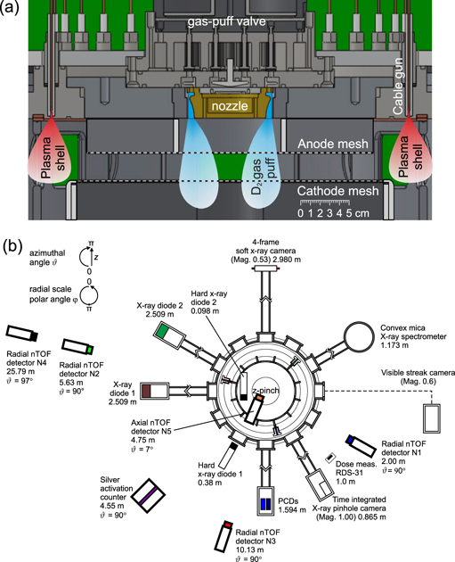
Figure 1. (a) Schematic diagram of the experimental arrangement with electrodes, gas-puff hardware, and cable guns on GIT-12. (b) On-axis view of the diagnostic setup. In-chamber diagnostics (ion and electron detectors, B-dot probes, neutron CR-39 detectors, activation samples, etc.) are not displayed.
Download figure:
Standard image High-resolution imageThe z-pinch dynamics and high-energy particles were observed by a comprehensive set of diagnostics. The electrical, optical, x-ray, gamma, and neutron detectors were described in references [24] and [59]. The most recent layout of diagnostics is displayed in figure 1(b). Figure 1(b) does not show in-chamber diagnostics. In the chamber, we placed B-dot probes, neutron activation samples, neutron CR-39 detectors, and electron and ion diagnostics. Ion diagnostic tools were presented in references [26, 60, 61]. The most important ion detectors and several new diagnostic techniques will be introduced later in this article.
The above-mentioned hybrid gas-puff z-pinch was fielded originally in 2013 [23]. Recently, we modified this z-pinch load. The modification consisted of an intermediate SS grid of 2 cm diameter that was placed inside the anode–cathode gap. In 2019, we carried out nine shots with the grid placed at various (0.6–1.1 cm) distances from the cathode. Figure 2(a) shows the shot with the grid positioned at 1.0 cm above the cathode mesh. The grid was connected to the cathode mesh by an on-axis SS wire of 300 μm diameter. The initial purpose of this configuration was the measurement of azimuthal magnetic fields via z-pinch-driven ion deflectometry [62, 63]. Interestingly, the shots with the inserted SS grid produced record ion energies and a large number of high-energy neutrons.
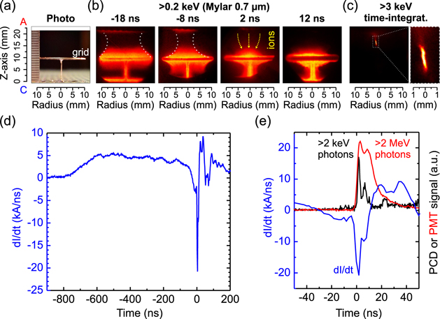
Figure 2. (a) Photo and (b) time-resolved soft x-ray images of the hybrid gas-puff z-pinch with the grid inserted in the anode–cathode gap. The time t = 0 corresponds to the sharp rise of >2 MeV bremsstrahlung emission. The anode is at the top and the cathode is at the bottom. The brightness is proportional to the amount of detected x-ray radiation. (c) Time-integrated x-ray image with a spatial resolution of 0.2 mm. (d) Current derivative dI/dt measured by the probe with ∼4 ns resolution at ∼30 cm radial position. (e) X-ray (>2 keV) and bremsstrahlung (>2 MeV) radiation detected by a photoconducting detector and a heavily shielded (20 cm of lead) nToF detector, respectively. Shot no. 2418 with (5.0 ± 0.9) × 1012 neutrons.
Download figure:
Standard image High-resolution imageThe grid evidently influenced the plasma dynamics at the end of the implosion. Soft x-ray images in figure 2(b) show the plasma accumulated at the grid surface and two spatially and temporally separated implosions. The plasma imploded first above the grid. (The boundaries of the imploding layer are set off by white dashed curves). The implosion below the grid was delayed by about 8 ns. The implosion velocity inferred from the soft x-ray images was up to 5 × 10⁵ m s−1. Shortly after the end of the implosion above the grid, the current disruption occurred as shown in figures 2(d) and (e). The current disruption was accompanied by the main neutron pulse and high energy (>2 MeV) bremsstrahlung radiation. The fast onset of the >2 MeV bremsstrahlung emission, namely 10% of its maximal value, is defined as time t = 0. We observed in previous experiments that the production of energetic particles started immediately, within a nanosecond accuracy, after the plasma expulsion from a neck that developed near the anode during stagnation [26]. A neck of 300 μm diameter and 2 mm length can be seen in the time-integrated x-ray image in figure 2(c). This image of >3 keV self-emission was detected in the pinhole camera by a rear RAR 2497 film which was placed behind a 10 μm thick Be foil and a frontal RAR 2497 film. After the disruption of the m = 0 constriction, the production of energetic (>1 MeV) particles lasted about 10 ns. As evidence of this, figure 2(e) shows the >2 MeV bremsstrahlung pulse with a 14 ns full width at half maximum (FWHM). The observed FWHM could be significantly broadened by scattered radiation and the 7 ns temporal resolution of our hard x-ray (nToF) detector. It should be noted that, due to the wide neutron spectrum, the radial nToF signal was broadened up to 50 ns (FWHM) already at the closest detector location 2 m away from the source. The total yield of >100 keV neutrons on the shot presented in figure 2 was (5.0 ± 0.9) × 1012. The fluence anisotropy of >1 MeV neutrons was measured with indium samples placed inside the experimental chamber [64]. The maximum neutron output of (1.0 ± 0.2) × 1012 neutrons/sr was observed downstream, i.e., in the anode to cathode direction. The ratio of forward to side neutron fluences was about 4. The energy input into the imploding z-pinch up to the end of neutron emission was Wzpinch = ∫VzpinchIdt = ∫(V − LdI/dt)Idt ≈ 130 kJ. As far as the ion emission is concerned, we will describe its characteristic features in the following section 3.
3. High-energy deuterons and protons
Energetic hydrogen ions up to 38 MeV were detected first in the earlier set of GIT-12 experiments focused on the neutron production [23]. Since then, we have improved the ion diagnostics to characterize ion emission and investigate acceleration mechanisms on GIT-12 [26, 60, 61]. One of the most useful ion-diagnostic techniques proved to be an on-axis detector which simultaneously measured angular, spatial, and spectral properties of the ion emission [26, 65]. A recent schematic of this detector is shown in figure 3(a). The angular distribution of the ion emission was measured by a beam-profile detector consisting of a stack of HD-V2 Gafchromic films and CR-39 detectors placed about 11 cm from the cathode mesh. The films and CR-39 detectors subtended a solid angle of about 0.25 sr. The effective area of the detectors was reduced by a shielding mask, collimators, and 3 cutouts (see figure 4). At the center of each cutout was a pinhole. Three pinholes were used to estimate ion emission anisotropy. The ion pinhole camera used a stack consisting of aluminum absorbers and absolutely calibrated radiochromic films (RCFs) to provide information on the spatial distribution as well as the energy spectrum of the accelerated ions. Ions with different energies were stopped in different layers. Deuterons with lower energies were stopped at the beginning of the stack. In contrast, deuterons with higher energies penetrated the first detectors and got stopped in the deeper layers of the stack. Using aluminium foils as intermediate layers in the stack extended the highest distinguishable energy. Protons and deuterons deposit their kinetic energy mainly at the end of their range (at the Bragg peak). The responses of ion detectors used in the pinhole camera and the beam-profile detector were modeled with the SRIM code [66]. The minimum deuteron energy required to reach a given layer is shown along with each ion image presented in this paper. Both parts of the axial ion detector shown in figure 3(a), i.e., the beam-profile detector and the 3-pinhole camera, recorded high-energy ions. The measurement by the 3-pinhole camera will be described first.
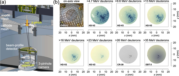
Figure 3. (a) Schematic showing the arrangement of the axial ion detector. Because of the charge and current neutralization of ion beams in a low pressure gas, we assume the ballistic transport below the cathode mesh. (b) Photograph with on-axis view of the cathode mesh with the grid and several selected images from the stack of HD-V2 films, CR-39 detectors, and EBT-3 films in the ion pinhole camera (detector type is labeled in the bottom left corner of each image). The detector darkness is proportional to the ion flux. Spatial scales correspond to the plane of the cathode mesh. The pinhole camera had a magnification of 0.58–0.63 and pinholes of 0.28 mm diameter. Shot no. 2418 with (5.0 ± 0.9) × 1012 neutrons.
Download figure:
Standard image High-resolution image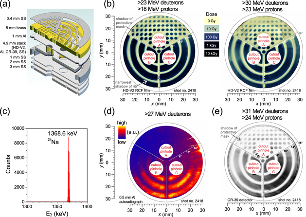
Figure 4. (a) Schematic of the beam-profile detector. (b) Images of the ion-beam profile detected by the second and third HD-V2 Gafchromic films at 11 cm away from the cathode mesh. (c) Post-shot gamma-ray spectrum of an aluminum absorber shown in (d). (d) Post-shot autoradiograph of the aluminum absorber placed behind the first HD-V2 film and recorded by the FOMA Indux R7 film. The brightness is proportional to the amount of activated nuclei. (e) Image of the ion-beam profile detected by the second CR-39 detector. The detector darkness is proportional to the number of ion tracks. Shot no. 2418 with (5.0 ± 0.9) × 1012 neutrons. The stack consisted of a 0.4 mm SS protective mask, 5 mm brass protective mask with cylindrical apertures, 1 mm aluminum-alloy (EN AW 2017) cover supported with 1 mm rubber mask, 0.1 mm aluminum absorber, the first HD-V2 film, 0.5 mm aluminum absorber, the second HD-V2 film, 0.75 mm CR-39 detector, 0.5 mm aluminum absorber, the third HD-V2 film, 0.75 mm CR-39 detector, 1 mm SS pad, 1 mm rubber, 1 mm SS pad, 2 mm SS pad, 3 mm SS pad.
Download figure:
Standard image High-resolution image3.1. Ion pinhole images
Figure 3(b) shows pinhole images of deuterons with energies between 4.7 and 35 MeV on the shot that is presented in figure 2. The ion pinhole camera for that shot had a cathode mesh-to-pinhole distance of 106 mm, 0.28 mm diameter pinholes, and a system magnification of 0.6. The pinhole camera used a stack that consisted of seventeen RCFs (HD-V2, EBT-3, XR-QA2 Gafchromic films) and CR-39 solid-state nuclear track detectors. RCFs are known to be sensitive to ions as well as to electrons and high-energy photons. Direct evidence that the beam was comprised of hydrogen ions (protons or deuterons) was therefore obtained from observation of proton- or deuteron-induced tracks in the CR-39 solid-state nuclear track detectors. From this point of view, it is important that there was agreement of the signals detected by the CR-39 detector and the Gafchromic films (see figure 3). In figure 3(b), we present seven selected images corresponding to one pinhole, which was closest to the center of the ion beam. The images cover the deuteron-energy range between 4.7 and 35 MeV. As can be seen in the pinhole images, the signal was recorded by all sensitive plates and films of the ion pinhole camera. At lower energies below 10 MeV, the deuterons were emitted from a larger (cathode) area. The shadows of the cathode mesh and the inserted grid are clearly visible. At higher energies, the deuterons originated from highly localized spots. Above 35 MeV, one sub-millimeter (3 mm off-axis) ion source was dominant. The stack of the RCFs and CR-39 detectors in the ion pinhole camera did not allow us to distinguish between protons and deuterons and recognize energies higher than 35 MeV. Energies above 35 MeV and the presence of high-energy deuterons were observed with the beam-profile detector, results of which are presented in the following subsection 3.2.
3.2. Beam profile of >20 MeV deuterons
The previous subsection 3.1 showed the images from the ion pinhole camera. This kind of ion detector has low sensitivity, since it detects only those ions that go through a distant pinhole. In our case, the 0.28 mm diameter pinhole was placed at a distance of about 11 cm from the cathode mesh. Even though the ion pinhole camera detected many hydrogen ions above 20 MeV, the analysis of the most energetic ions was performed with the beam-profile detector.
As illustrated in figure 3, the beam-profile detector was located at the top of the on-axis ion detector. Figure 4(a) shows a more detailed view of the individual layers that constituted the detector. The upper part consisted of SS and brass protective masks with cylindrical apertures that allowed rough estimation of the location of the ion source [67]. Then, a special stack of HD-V2 Gafchromic films, CR-39 detectors, aluminum foils, and stainless steel pads was placed below a 1 mm thick aluminum-alloy (EN AW 2017) absorber to measure the ion-beam profile and hydrogen-ion energies above 20 MeV. In the beam-profile images presented in figure 4(b), the shadow of the shielding mask is clearly visible. The HD-V2 films behind 1 mm thick aluminum alloy were saturated by ≳20 MeV hydrogen ions, i.e. the doses were above 1 kGy. The energies detected by the third HD-V2 film corresponded to >23 MeV protons or >30 MeV deuterons. Confirmation that deuterons significantly contributed to the pattern seen in the HD-V2 film was obtained by nuclear activation analysis of the aluminum foils.
Figure 4(d) presents an autoradiograph of the aluminum foil that was placed in front of the second HD-V2 film in the stack. Comparing figures 4(b) and (d), one can see some correspondence between the autoradiography image and the beam-profiles recorded by the HD-V2 Gafchromic films. The autoradiography image was obtained by placing the aluminum foil directly on a piece of FOMA INDUX R7 film at about 24 h after the shot. This film recorded the gamma rays from the activated aluminum. By using a Canberra GC5019 high-purity Ge detector, we found 24Na radioisotopes with a 15 h half-life to be dominant in the post-shot gamma-ray spectrum as shown in figure 4(c). The 24Na isotopes were most likely produced by nuclear reactions of accelerated deuterons with the aluminum absorber. The 27Al(d, x)24Na nuclear reaction has a significant (>3 × 10⁻⁵) thick-target yield for deuterons above ∼17 MeV. Therefore the deuterons needed to have an energy above 27 MeV to penetrate the stack of 0.25 g cm−2 areal density with a residual energy of at least 17 MeV. By the nuclear activation method, we calculated that the number of >27 MeV deuterons emitted into a 550 mrad cone was (5.8 ± 2.3) × 1012. Part of the uncertainty arises from the fact that we do not know exactly the deuteron energy spectrum. Within this uncertainty, we obtained the same number of ≳30 MeV deuterons by the analysis of the HD-V2 films. If we assume that radiation dose at the calibrated HD-V2 films was given by deuterons and that an average energy loss of one deuteron in the HD-V2 active layers was 1 eV Å−1, we will find out that the total number of >30 MeV deuterons emitted into 0.25 sr was (6.6 ± 3.0) × 1012. The agreement between the nuclear activation and the HD-V2 analysis means that the radiochromic images in figure 4 were produced predominantly by deuterons.
The fact that the ion beams consisted mainly of deuterons helped us to reconstruct a deuteron energy distribution function. The absolute deuteron energy spectrum was estimated from the stack of RCFs and aluminum foils in the beam-profile detector (see figure 4). Spectral responses of the films and foils were calculated with the SRIM ion transport code [66] and EXFOR [68] or TENDL [69] nuclear data libraries. The numbers of the films and the foils were not sufficient to unfold the absolute deuteron energy spectrum precisely. Therefore we infer the deuteron spectrum by using a forward analysis and assuming a power-law  or exponential fall-off f(Ed) ∝ exp(−Ed/T) of the deuteron energy spectrum. The experimental data fit best for the values shown in figure 5 and for the spectrum with an exponential slope temperature T = (7 ± 1) MeV.
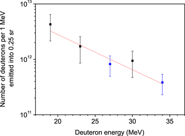
Figure 5. Deuteron energy distribution function reconstructed from the HD-V2 films (black squares) and the activated aluminum foils (blue squares) in the beam-profile detector. Shot no. 2418 with (5.0 ± 0.9) × 1012 neutrons.
Download figure:
Standard image High-resolution imageThe absolute values in figure 5 represent the number of the ions which impacted our axial detector. Figure 4 shows that the high-energy deuterons hit the entire surface of the beam-profile detector. The axial detector subtended a solid angle of 0.25 sr, which corresponds to ion emission into a 550 mrad cone. To estimate the number of ions emitted into a larger angle, we used a ring-shaped ion-beam detector that was placed under the cathode mesh as shown in figure 6.

Figure 6. (a) Schematic of the ring-shaped ion-beam detector below the cathode mesh. The stack of the ring-shaped detector consisted of a 1 mm aluminum cover, a 0.4 mm Teflon absorber, the HD-V2 Gafchromic film, and a 1 mm rubber pad. (b) Post-shot autoradiograph of the aluminum cover of the ring-shaped ion detector recorded by the FOMA Indux R7 film. The brightness is proportional to the number of activated nuclei. (c) Image of the ion-beam profile detected by the HD-V2 Gafchromic film. The plane of the cathode mesh is defined as z = 0. Shot no. 2418 with (5.0 ± 0.9) × 1012 neutrons.
Download figure:
Standard image High-resolution imageHD-V2 Gafchromic film was placed inside this detector. This film detected ions at angles ranging from 0.6 to 1.2 rad with respect to the z-axis and the center of the cathode mesh. The HD-V2 film recorded a high dose, even close to the cathode mesh, i.e., at a large angle of 1.2 rad from the z-axis. The emission was evidently anisotropic, based on the pattern of exposure shown in figures 6(b) and (c). The absorbed dose was higher in the polar direction which corresponded to the intense ion beam recorded in figure 4(d). An interesting feature in figure 6 is the shadow of wires, most likely of the cathode mesh. The shadow can be seen also in the post-shot autoradiograph of the aluminum cover of the ring-shaped detector. The autoradiograph recorded the gamma decay of aluminum atoms activated by deuterons. The correspondence of the autoradiography image and the radiochromic film indicates that the RCF signal was produced by deuterons. Analyzing the dose absorbed in the HD-V2 Gafchromic films shown in figures 4 and 6, we estimated that the total number of ≳20 MeV deuterons was (4 ± 1) × 1013.
3.3. Hydrogen ions with >50 MeV energy
The previous subsection 3.2 presented the spatial profile of the deuteron beam with energy of about 30 MeV. Up to 30 MeV (minimum deuteron energy), our ion detectors recorded ∼kGy doses, which were significantly above detection limits (∼10 Gy). It was, therefore, reasonable to analyze the deuterons with energies above 30 MeV. For this purpose, we used a nuclear activation technique again. We performed post-shot gamma-ray spectroscopy of grade 304 stainless steel pads containing (by mass) 70% iron, 19% chromium, and 9% of nickel, as well as other minor constituents. These SS pads were placed below the stack of the HD-V2 Gafchromic films, CR-39 detectors, and aluminum absorbers [see figure 4(a)]. In the gamma-ray spectra of the SS pads, we found the characteristic gamma emission of 52gMn and 55Co isotopes with 5.6 day and 17.5 h half-lives, respectively, as shown in figure 7(a). These isotopes, which have been researched as potential medical radionuclides [70], are known to be produced by bombardment of SS with fast protons and deuterons. The 52gMn ground states originated most-likely from the reactions of hydrogen ions with chromium, namely from the 52Cr(p, n) or 52Cr(d, 2n) nuclear reaction. The 55Co isotopes were produced by the interaction of hydrogen ions with natural iron, namely by the 56Fe(p, 2n) or 54Fe(d, n) nuclear reactions. Before we measured absolutely the yield of radionuclides with the post-shot gamma-ray spectroscopy, great care was devoted to the cleaning of the samples from impurities. We wanted to be sure that the pads were activated only by ions penetrating all the stack in front of a given pad. Significant activation by protons or deuterons was observed up to and including the next-to-last, 2 mm thick, SS layer [see figure 4(a)]. The last layer was activated only by neutrons, implying a low number of >65 MeV protons and >90 MeV deuterons. To activate the next-to-last layer, ions had to penetrate an areal density of about 3 g cm−2 and the residual ion energy still had to be sufficient to initiate the nuclear reactions. A conservative estimate of the maximum ion energies is based on the assumption that the next-to-last layer was activated by protons. (Besides protons injected by the cable guns, hydrogen contaminants could also be present at the surface of the electrode meshes). Assuming this, we modeled the nuclear activation response of the SS layers to protons using the SRIM code [66] and nuclear cross-section data [68, 69, 71]. The activation response of the next-to-last SS layer is displayed in figure 7(b).
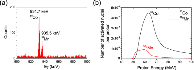
Figure 7. (a) Gamma-ray spectrum of the next-to-last, 2 mm thick SS pad activated by hydrogen ions on shot no. 2418 with (5.0 ± 0.9) × 1012 neutrons. (b) Modeled nuclear activation response (to protons) of the next-to-last SS pad in the beam-profile detector.
Download figure:
Standard image High-resolution imageFigure 7(b) shows that the minimum proton energy to activate the given layer was 50 MeV. The production of the 55Co radionuclides was efficient for proton energies above 55 MeV. The fraction of 56Fe nuclei in SS is about four times higher than the fraction of 52Cr. The peak yield from the 56Fe(p, 2n)55Co reaction is, therefore, higher than from 52Cr(p, n)52gMn. One would therefore expect protons to induce more 55Co than 52gMn. Based on the intensities of the spectral lines in figure 7(a), we estimated an almost identical number of 52gMn and 55Co radionuclides. It is, therefore, possible that fast deuterons contributed to the production of 52gMn isotopes via the 52Cr(d, 2n) nuclear reaction. If the next-to-last layer was partly activated by deuterons, those deuterons would have needed an energy higher than 70 MeV. However, the presence of such energetic deuterons is not unambiguous due to uncertainties in our gamma-ray measurements, nuclear data, and ion energy spectra. Regardless of whether protons or deuterons caused the activation of the SS pads, the measured numbers of 52gMn nuclei allowed us to calculate that at least (1.1 ± 0.6) × 1011 hydrogen ions with energies above 50 MeV were emitted into the 550 mrad cone.
Alternatively, we can estimate the maximum ion energies in our experiment by analyzing the shadow of the protective mask in the beam-profile images shown in figure 4. An energy of 60 MeV is not sufficient for protons to penetrate through 0.4 mm SS, 5.0 mm brass, and 1.1 mm thick aluminum-alloy layers. Therefore the shadow of the protective mask and ribs is clearly visible in figures 4(b) and (e). Assuming that the ions were emitted from one localized source above the grid near the z-pinch axis [see the most energetic ions in figure 3(b)], the ion beam had to pass the off-axis parts of the protective mask at an oblique angle. Then the width of the annular ribs depended on the ion energies. The higher the ion energy was, the narrower the shadow that was formed. The narrowest shadows of the annular ribs were detected in the lower parts of the beam-profile images displayed in figure 4(b). These parts correspond to the places where we detected the highest number of >30 MeV ions. Based on the smallest width of the shadow in the beam-profile images, we obtained maximum proton and deuteron energies of (50 ± 7) MeV and (67 ± 10), respectively. This method of assessing the ion end-point energies provides only a rough estimate because of the uncertainties in the ion source position and ion scattering in the various materials. Therefore, we want to give another proof of >50 MeV hydrogen ions in our experiment. For this purpose, we will present the results from neutron detectors in the following section 4.
4. Generation of neutrons with energies up to 60 MeV
We have shown in section 3.3 that our hybrid gas-puff z-pinch accelerated a significant fraction of hydrogen ions above 50 MeV. Ion energies of about 50 MeV were also confirmed indirectly by neutron detection. Figure 8 displays radial nToF signals measured at 10.13 m in 3 different configurations at the same current. The black curve shows a significant 2.5 MeV DD neutron peak on a shot with a standard D2 gas-puff z-pinch. The blue curve displays a broader neutron signal up to almost 20 MeV from a shot when the plasma shell was injected around the gas-puff. The red line represents the shot with both the plasma shell and the deflectometry grid that was placed 1 cm above the cathode mesh. We measured the neutron emission time by 4 radial nToF detectors that were placed at 2.0 m, 5.6 m, 10.1 m, and 25.8 m from the z-pinch. Analyzing the time-of-flight signals from these detectors, we found out with one nanosecond accuracy that the main neutron emission started during the fast onset of the >2 MeV bremsstrahlung pulse [see figure 2(e)]. Assuming that the neutrons were produced during this onset, we obtain the neutron energies that are displayed at the top of the graph shown in figure 8.
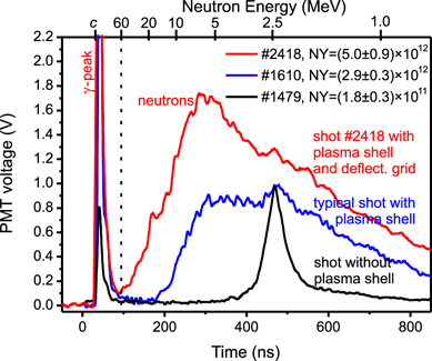
Figure 8. Radial nToF signals at 10.1 m from the deuterium gas-puff without the plasma shell (black line, shot 1479), with the plasma shell (blue line, shot 1610), and with both the plasma shell and deflectometry grid (red line, shot 2418). The relative scale of the y-axis is the same for all waveforms.
Download figure:
Standard image High-resolution imageAs illustrated in figure 8, the hybrid gas-puff configuration with the deflectometry grid produced not only energetic ions but also high energy neutrons. Naturally, >10 MeV protons and deuterons can generate neutrons via various reaction channels. Besides the D(d, n)3He reaction, the cross-section of which decreases above 2 MeV deuteron energy, deuterons with >10 MeV energy might produce significant neutron yields through the (d, np) deuteron break-up process, 27Al(d, xn), 56Fe(d, xn), and other reactions of fast deuterons with the experimental hardware [59]. In addition to that, (p, xn) reactions in aluminum and SS also have high (>100 mb) cross-sections for protons above 10 MeV. These nuclear reactions produce neutrons that carry information about ion beams: the neutron energy is determined, among other factors, by the energy of the incoming ion and the Q-value of the nuclear reaction. In our experiment, the Q-values of the relevant nuclear reactions are significantly smaller than the energy of the fastest ions. Therefore we can assume that the maximum achievable neutron energy is comparable to the end-point energy of the accelerated ions. It should be noted that, in the case of heavier elements, the final nuclei often remain in excited states. Therefore forward neutron spectra cover a broad range from sub-MeV energies up to about the projectile energy. In other words, some neutrons can reach the same energy as the fast ions but their fraction is low. From this point of view, the maximum neutron energy observed in figure 8 provides another confirmation of a significant number of ≳50 MeV protons or deuterons in our experiment.
The maximum neutron energies in our experiment were detected by the axial nToF detector, which was placed at 4.75 m below the cathode mesh. On the shot with the hybrid gas-puff configuration and with the deflectometry grid, the axial nToF detector detected neutrons with an energy up to 58 ± 7 MeV. Interestingly, a similar maximum neutron energy of 56 ± 5 MeV was also observed by the radial nToF detector placed at 10.13 m (see figure 8). To explain it, we note that this radial detector was placed in the direction where we observed the high ion signal on the ring-shaped ion beam detector, as shown in figure 6. Based on the axial and radial nToF signals we estimated the yield of >50 MeV neutrons to be (4 ± 3) × 108. A relatively high statistical error originated from the uncertainty of the detector sensitivity to 50 MeV neutrons, neutron emission anisotropy, and large detector distances resulting in low numbers of detected neutrons. However, even the lower bound estimate of the >50 MeV neutron yield is high enough to confirm the presence of energetic deuterons or protons in our experiments. These fast ions are assumed to be accelerated towards the cathode by strong electric fields. The electric fields should accelerate electrons in the opposite direction, i.e., towards the anode. Therefore, we carried out a fast-electron measurement that is presented in the following section 5.
5. Electron energy distribution function
Relativistic electron beams on GIT-12 were detected in both axial directions, i.e. above and below the z-pinch. However, as expected, we observed that the most intense electron beams were emitted towards the anode. In this direction, there was gas-puff hardware which partially limited our diagnostic capabilities. To measure electron energy spectra, we placed a relatively compact magnetic spectrometer inside the gas-puff nozzle as shown in figure 9(a). The distance from the anode mesh to the collimator at the entrance to the magnetic spectrometer was 35 mm. In the region between the anode mesh and the collimator, there was low pressure, likely photoionized, deuterium gas. We assume that the electron beam was partially charge- and current-neutralized before it entered the magnetic spectrometer. The maximum field inside the dipole magnet spectrograph reached 0.5 T. The electron beam was detected by an FWT-60 radiochromic film. This relatively low sensitivity film was placed behind 20 μm Al and 50 μm Ta foils to reduce x-ray background. The stopping power for the electrons in this detector stack was calculated by the ESTAR program provided by the National Institute of Standards and Technology (NIST) [72]. The energy scale of the spectrometer was determined by measuring the magnetic field with a magnetometer and calculating the particle trajectories inside the spectrometer with our relativistic charged-particle tracking code.
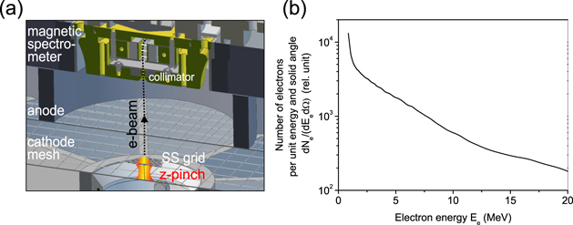
Figure 9. (a) Schematic of the magnetic electron spectrometer. (b) Electron energy distribution function detected by an FWT-60 radiochromic film on shot no. 2418 with (5.0 ± 0.9) × 1012 neutrons.
Download figure:
Standard image High-resolution imageFigure 9(b) shows the electron spectrum obtained on shot 2418 (the same shot as presented in all previous figures 2–8). In the region between 2 and 10 MeV, the observed energy spectrum can be fitted with an exponential fall-off with a slope temperature of 5 ± 1 MeV. The energy spectrum above 10 MeV is not certain due to the finite spectrometer resolution and the proximity of >10 MeV electrons to a non-deflected signal caused by x-rays and collectively accelerated ions. The spectrometer resolution was limited by the relatively short distance available for the electrons to be collimated and deflected, and by collective effects of the non-fully neutralized electron beam on the electron trajectories. Despite the limited resolution, the z-pinch on GIT-12 evidently accelerated not only >10 MeV deuterons but also ≳10 MeV electron beams. The electron spectrum was recorded by the FWT-60 film that is sensitive to doses in the range between 0.5 and 200 kGy. To deliver a measurable dose into the FWT-60 film, the number of 10 MeV electrons had to be sufficiently high (>1012 per cm2). Therefore, we assume that the end-point energy of the electron beam was likely significantly higher than 10 MeV.
The interaction of the intense relativistic electron beam with the anode naturally leads to the generation high-energy bremsstrahlung radiation [see figure 2(e)]. Analysis of the bremsstrahlung emission might have revealed further details about the relativistic electrons. The bremsstrahlung radiation in our z-pinch experiments is supposed to exceed thresholds of photonuclear reactions. We therefore considered photodisintegration reactions that would help us to characterize the multi-MeV bremsstrahlung radiation. However, for a given projectile energy, the cross-sections of photodisintegration reactions, e.g. (γ, n), are smaller than those of neutron-initiated nuclear reactions producing the same final nuclei, e.g. (n, 2n). So far, the high number of >10 MeV neutrons in our experiment has prevented us from analyzing the bremsstrahlung radiation with nuclear activation techniques. Most information about the bremsstrahlung radiation was, therefore, inferred from the x-ray peak preceding the nTOF signals recorded by fast scintillator-photomultiplier tube (PMT) combination detectors [73]. As shown in figure 2(e), these detectors were used to measure the duration of the bremsstrahlung radiation. The only information about the photon energies was obtained from the thickness of the lead shielding. The large PMT signal behind 20 cm of lead indicated that an abundance of photons with an energy above >2 MeV were emitted during the z-pinch disruption. A fraction of the PMT signal could also be ascribed to gamma rays from nuclear reactions. However, in that case, it would be difficult to explain the observed anisotropy of the high-energy photons that were emitted largely towards the anode. We therefore assume that the intense pulse of >2 MeV photons was generated by the impact of the relativistic electron beam onto the anode hardware.
6. Discussion
6.1. 60 MeV ions from hybrid gas-puff z-pinch
Deuterium z-pinches have been predominantly researched as sources of DD fusion neutrons [74, 75]. This was also the reason for our first deuterium gas-puff experiments on GIT-12 in 2011 [76]. In the initial experiments on GIT-12, we optimized the z-pinch load with respect to high neutron yields. We found out that a very efficient source of fast neutrons is the hybrid configuration of the gas-puff z-pinch [23, 24]. The neutron yield of 3.6 × 10¹² at a 60 kJ energy input implied a neutron production efficiency of 6 × 10⁷ neutrons per one joule of plasma energy. Since 2015, our interest has been concentrated on the primary cause of the neutron production, i.e., on the acceleration of deuterons. To characterize ion emission and acceleration, we used many techniques, including several novel (to z-pinches) diagnostic methods. Up to 2018, the maximum hydrogen ion energy observed in our experiments was 38 MeV. The total number of the most energetic ions was not estimated. In 2019, we placed the intermediate SS grid at about 1 cm above the cathode mesh on several shots as shown in figure 2(a). This z-pinch configuration with the grid produced large numbers of high-energy deuterons and neutrons. The deuteron energy distribution function seemed to follow an exponential fall-off with a certain cut-off energy. The end-point energy of hydrogen ions and neutrons approached 60 MeV.
It is natural to ask why the shots with the intermediate SS grid produced the highest energies. We hypothesize that the z-pinch length optimal for the highest ion energies is smaller than the ∼25 mm anode–cathode gap that is usually used in our experiments. The intermediate grid led to two separate implosions, namely above and below the grid. Due to the separation of two implosions in time, the GIT-12 generator, even though it has a high inductance, could compress a shorter z-pinch column to a smaller diameter more easily than the total z-pinch length [77]. An indication of a tightly compressed plasma column can be seen in the compact region of high-energy x-ray emission shown in figure 2(c). When the conduction current concentrated on the axis is disrupted, ions could be accelerated by the induced electromagnetic pulse [27]. In figure 3(b), we can see the ion pinhole images with the shadow of the SS grid, especially the squares near the z-pinch axis. This means that deuterons were accelerated above the grid, likely in the low-emission region after the plasma ejection from necks as illustrated in figure 2(b) at 2 ns. Usually, these ions were typically accelerated as microbeams from several localized ion source spots in the plasma. These ion microbeams produced stripes in the beam-profile detector (see e.g. reference [26]). The beam-profile images presented in this paper indicated more homogeneous irradiation. As shown in figure 6, the ions produced a beam-profile image that included a discernible shadow of the cathode mesh, as in point-projection radiography. This suggests that there was one dominant, divergent source of >20 MeV deuterons and that the beam laminarity was not destroyed by azimuthal magnetic fields around the z-pinch. We assume that the ion source corresponded to the axial region where the z-pinch neck was disrupted.
6.2. High-energy ions in independent experiments on HAWK (US Naval Research Laboratory)
The previous sections 2–5 demonstrated that the hybrid deuterium gas-puff experiments on GIT-12 provided us with some unique results. An illustrative example is the end-point energy of hydrogen ions that approached 60 MeV. 60 MeV energy is one hundred times the ion energy provided by the generator driving voltage of 0.6 MV and the highest energy of charged particles observed in pulsed power devices. (As the previous record, we consider a 50 MeV, 1 kA electron beam accelerated on the upgraded PHERMEX electron linac radiography machine [78].) It was therefore highly desirable to confirm the results from GIT-12 in an independent experiment on another device. For this purpose, we carried out several experimental campaigns on the HAWK generator at the US Naval Research Laboratory in Washington [79]. HAWK is a high-inductance (607 nH) generator that might resemble one module of GIT-12. At an 80 kV charging voltage, HAWK stored an energy of 0.22 MJ and delivered a 0.64 MV, 0.7 MA pulse to a load with a 1.2 μs rise time. The similar architecture but different peak currents of GIT-12 and HAWK enabled us to study the scaling of charged-particle acceleration with current. The HAWK generator was used to drive a plasma-shell on deuterium gas puff as on GIT-12. Both experiments, i.e., on GIT-12 and HAWK, have been described and compared in our recent paper [21]. Up to 2018, we observed 8 MeV deuterons at 0.6 MA on HAWK and 38 MeV hydrogen ions at 2.6 MA on GIT-12. Based on these values, we suggested that, under optimal conditions, the ion energies scale approximately linearly with current. In 2019, we continued with the optimization of the z-pinch loads and we achieved more energetic ions and neutrons both on GIT-12 and HAWK. This paper reports hydrogen ions above 50 MeV at 2.7 MA current on GIT-12. On HAWK (without a grid), we observed the maximum deuteron energy of at least 10 MeV at 0.6 MA current [80]. When we take into account a lower number of shots and less experience with the optimal load on HAWK, the suggested linear scaling of ion energies with current remains a good approximation. Regardless of the scaling, the deuteron energies on HAWK were significantly higher than those corresponding to the generator output voltage. The voltage multiplication in the independent experiment is crucial since it confirms the unique results obtained with the hybrid gas-puff z-pinch on GIT-12.
6.3. Energies and ion numbers in laser-based ion sources
Acceleration of protons and deuterons is a research topic of great interest in plasma physics. In the past two decades, ion beam generation in laser-driven accelerators has been particularly well-studied. Around 2000, intense multi-MeV proton beams were produced by target normal sheath acceleration (TNSA) during irradiation of thin solid targets by ultra-high intensity lasers [4, 5]. The petawatt laser at the Lawrence Livermore National Laboratory accelerated 2 × 10¹³ protons above 10 MeV. The maximum proton energy reached 58 MeV. These results promptly triggered great research activities on ion acceleration by lasers. However, despite this huge effort, the ion numbers and maximum proton energy from those LLNL petawatt laser experiments remained the record values for a decade and have been exceeded only in a few more recent experiments [6, 81]. From this point of view, it might be interesting to show the breakthrough results obtained on the LLNL laser together with the values achieved in our z-pinch experiment.
Figure 10 presents a comparison of ion energy distribution functions in our z-pinch experiment and in the laser experiment at LLNL. Interestingly, the number of high-energy ions and the end-point energy on the terawatt GIT-12 pulsed power generator were comparable or even higher than in the petawatt laser system. We should note that the displayed ion numbers on GIT-12 represent only that part of the ion beam which was accelerated into 0.25 sr and went through the SS grid and the cathode mesh with 56% and 70% transparencies, respectively. In addition to that, the GIT-12 values in figure 10 represent deuterons that are generally more difficult to accelerate than protons. As far as deuterons accelerated by lasers are concerned, experiments have been carried out on Trident at LANL [84–86] and Phelix at GSI Darmstadt [87]. The deuterons in these laser experiments were accelerated by TNSA or break-out afterburner (BOA) mechanisms. Then the deuterons were used to generate neutrons inside beryllium converters. To the best of our knowledge, Trident has produced the most energetic neutrons among the state-of-the-art lasers. In a recent experiment on Trident [86], the highest distinguishable energy in the neutron distribution was 55 MeV. Comparing neutron ToF signals in figure 6 of reference [86] with our signal in figure 8, we can see that the maximum neutron energy on Trident was almost the same as on GIT-12. Overall, this is an exciting result considering that our z-pinch experiment requires neither modern pulsed power technology nor state-of-the-art lasers.

Figure 10. Deuteron and proton energy distribution functions on the terawatt (4.7 MA, 0.6 MV) GIT-12 z-pinch facility (squares) compared with the petawatt (400 J, 500 fs) laser system (circles) at the Lawrence Livermore National Laboratory. The LLNL data were taken from Snavely et al [5] the GIT-12 values were calculated from the ion pinhole camera (gray squares), the beam-profile detector (black squares), and the SS pad (red square). As for the ion pinhole camera, the deuteron spectrum below 20 MeV was obtained from the HD-V2 RCFs through RCF stack spectroscopy [82, 83]. To obtain absolute numbers of the deuterons, we assumed homogeneous ion emission into 0.25 sr and calculated with the average deuteron spectra detected by three ion-pinhole cameras.
Download figure:
Standard image High-resolution image
7. Conclusions and future work
In this paper, we demonstrated that the hybrid gas-puff z-pinch on the GIT-12 generator is a powerful source of >10 MeV electrons, deuterons, and neutrons. Under optimal conditions, the total numbers of hydrogen ions with energies above 20 and 50 MeV were 4 × 10¹³ and 1011, respectively. These values are similar to those obtained with the state-of-the-art lasers. By this statement, we do not mean to indicate that z-pinches can be competitors of laser-based sources. Many properties of ion beams produced by lasers and z-pinches are significantly different. By the comparison of the z-pinch with state-of-the-art lasers, we intend to show that ion acceleration mechanisms in z-pinches could be very efficient and attractive.
In a previous paper [26], we presented a mechanism that is based on Trubnikov's idea of the disruption of the conduction current [27]. A fast drop in the electric current generates a voltage V ≈ −LdI/dt, where L is the inductance which corresponds to the disrupted current-carrying column. In order to reach high induced voltages V, the mechanism of current disruption should be fast and should hold off high transient electric fields. The main principle of power and voltage multiplication is analogous to opening switches used in inductive energy storage systems [88]. The behavior of the hybrid gas-puff z-pinch on GIT-12 can be characterized as a high-density plasma opening switch with a microsecond conduction time, 3 MA conduction current, nanosecond opening, >20 Ω impedance after opening, and >60 MV stand-off voltage. These are unique properties of the z-pinch disruption that can be employed in pulsed-power technology, especially in the fast transport of current into an on-axis load.
Current disruption is a quite general phenomenon that explains, e.g., charged particle acceleration in the Earth's magnetosphere [28, 29] and neutral current sheets [54], x-ray production in laboratory plasma jets [30], runaway electrons in tokamaks [31], the formation of collisionless shocks in laser-produced plasmas [89], and high voltages in low pressure discharges [90, 91]. Of course, the physics behind current disruption may be different in each of the cases mentioned above. Interestingly in low-pressure arcs, the current drop was explained by the pinch effect as early as in 1937 [90]. As for the pinch effect, its high impedance is usually attributed to the implosion of necks [8, 36–40] or to anomalous resistivity [42–46]. However, neither fast implosion nor anomalous collisions could account for the peak impedance of ≳10 Ω and ion emission parameters observed on GIT-12 (see reference [26] for more details). Consequently, we suggested that the high impedance was caused by a space-charge limited flow [92] or self-magnetic insulation in a gap formed after the ejection of plasmas from an m = 0 instability. Z-pinches are known to be susceptible to magnetohydrodynamic instabilities, particularly a symmetric m = 0 mode. Since stable implosion and stagnation are essential for high x-ray power levels and thermonuclear yields, much effort within the z-pinch community has been devoted to suppressing all kinds of instabilities. In our research, we try to follow a different paradigm. We do not want to suppress all instabilities in our z-pinch experiments (e.g. by axial magnetic fields or additional mass in a central jet). On the contrary, we attempt to optimize the process that naturally occurs in z-pinches, x-pinches, and dense plasma foci [51, 52].
On GIT-12, we used our evolved understanding of the acceleration mechanism, and we let instabilities develop in an efficient way. By adjusting the initial conditions, we created powerful ion beams with hydrogen energies approaching 60 MeV. Calculating with the 7 mm gap observed in figure 2(b), 60 MeV ions required ≈10 GV m−1 electric fields. These fields could be generated by the decrease of a megaampere conduction current with a sub-nanosecond decay time [26].
Despite this more detailed knowledge of the ion acceleration in z-pinches, many details explaining the process of the current disruption remain unclear. In particular, there is a need to benchmark numerical codes that simulate the z-pinch dynamics after the ejection of plasma from constrictions. A full understanding of the acceleration mechanism in z-pinches is important for several reasons. First, considering the natural occurrence of current-carrying columns in laboratory and space plasmas, the ion acceleration in z-pinches could represent a more general physical process that contributes to the efficient production of particle beams in various plasmas. Second, z-pinch-based sources can be used in various applications requiring powerful ion and neutron pulses of nanosecond duration. We can find inspiration in laser-based sources where ion beams are applied to probe electric and magnetic fields [93] and neutrons are used to study r-process in stars [94, 95]. In the future, we would like to employ accelerated ions to study magnetic field and current density profiles in z-pinches. We believe that the new diagnostic method could shed more light on this long-lasting problem of z-pinch physics.
Acknowledgments
The authors acknowledge O Sila for his help with MCNP (Monte Carlo N-particle code) simulations. This research has been supported by the Grant Agency of the Czech Republic (Grant No. 19-02545S), the Czech Ministry of Education (Grant Nos. LTAUSA17084, LTT17015 and CZ.02.1.01/0.0/0.0/16_019/0000778), the Czech Technical University in Prague (Grant No. SGS19/167/OHK3/3T/13), the Naval Research Laboratory Base Program, and TPU Competitiveness Enhancement Program Grant.