


Abstract
The effect of the zitterbewegung consisting in trembling of trajectory of propagating particles may, in principle, be found in a variety of physical systems characterized by split kinetic energy dispersion branches. However, in a majority of material systems the effect is too weak to be observable. Specially designed semiconductor heterostructures representing optical microcavities with embedded quantum wells allow observing the zitterbewegung of exciton–polaritons that are optical cavity modes strongly hybridized with excitons in quantum wells. Here we show that external magnetic fields applied in the plane of the microcavity amplify this effect and allow for tuning the amplitude and the period of oscillations of polariton trajectories, thus being a convenient tool of control. These results pave the way towards realization of ballistic polariton transistors based on the spin–orbit effect, conceptually similar to Datta-and-Das transistors.
Export citation and abstract BibTeX RIS

Original content from this work may be used under the terms of the Creative Commons Attribution 4.0 licence. Any further distribution of this work must maintain attribution to the author(s) and the title of the work, journal citation and DOI.
1. Introduction
The effect of the zitterbewegung manifests itself in the appearance of oscillations of trajectories of propagating particles due to the correlations between some of its degrees of freedom. First predicted for free Dirac electrons [1], it later was generalized to a wide variety of systems characterized by split kinetic energy dispersion branches. Among them are trapped ions [2], Bose–Einstein condensates of ultracold atoms [3], two-dimensional photonic crystals [4], binary waveguide lattices [5], mono- and bilayer graphene, and carbon nanotubes [6]. A separate group of systems with gapped kinetic energy spectra are spin-split systems, where the degeneracy in energy is lifted for states with different internal degrees of freedom (spin and/or polarization). The spin–orbit coupling (SOC) which is the mutual influence of the internal degree of freedom of a particle and the external degrees of freedom associated with its macroscopic behavior [7, 8], is at the origin of the characteristic energy splittings of kinetic energy branches in such systems. The manifestation of the zitterbewegung oscillations induced by the spin–orbit interaction (SOI) in a condensate of ultracold boson atoms was reported in [9]. In solid state systems, the zitterbewegung of electrons induced by the SOC due to the Rashba and Dresselhaus effects in semiconductor structures was demonstrated [10, 11].
In the recent paper [12], some of us predicted theoretically the zitterbewegung of macroscopic wave packets of exciton–polaritons in a two-dimensional optical microcavity with embedded quantum wells (QWs). Exciton–polaritons are mixed states formed from the microcavity photon modes strongly coupled to the QW excitons [13]. The predicted in [12] zitterbewegung comes from the optical constituent of the polariton state. The splitting in the transverse electric and transverse magnetic cavity modes (TE–TM splitting) is at the origin of this effect. The magnitude and observability of the predicted zitterbewegung are limited by the fact that the period of oscillations increases quadratically with the polariton wave number k, and because the amplitude of the oscillations is inversely proportional to k. Moreover, the contribution of the photonic component to the exciton–polariton state weakens with the increasing k. Consequently, the effect is only observable in a narrow range of k close to the bottom of the low-branch polariton dispersion, where it closely approaches the parabolic cavity photon dispersion. This also results in a fast broadening of the polariton wave packet which obscures the effect of the zitterbewegung.
In the present work, we are taking advantage of the composite nature of exciton–polaritons that allows one to significantly expand the conditions favorable for the manifestation of the zitterbewegung. Taking into account the energy splitting of the exciton state induced by the external magnetic field we were able to efficiently compensate reduction of the zitterbewegung caused by the weakening of the photon contribution with the increasing wave vector. In [14–18], it was shown that the splitting of linearly polarized exciton states occurs under the effect of the external magnetic field applied in the Voigt geometry (in the cavity plane) as a result of the magneto-induced mixing of optically active (bright) exciton states with optically inactive (dark) states. The magnitude of the splitting depends quadratically on the magnitude of the applied magnetic field. The external magnetic field is known as an effective tool for controlling polarization properties of exciton–polaritons, however the Voigt geometry remains undeservedly deprived of attention, being overshadowed by the Faraday geometry [19–23]. The recent paper [24] is devoted to the experimental study of the joint effect of the TE–TM splitting of cavity modes and the splitting of excitons induced by the in-plane magnetic field on the polariton polarization dynamics in real space. The variation of the period of polarization beats due to the interplay of photon and exciton mechanisms of the energy splitting and the suppression of oscillations when the splitting effects compensate each other were demonstrated.
In the discussed experiments, as well as in the vast majority of the previous studies of the spin-split excitons, attention was paid to the effect of SOI on spin (polarization) transport of excitons or exciton–polaritons, see e.g. [22–31]. Here we underline that SOI implies the mutual influence of the spin and orbital degrees of freedom of polaritons. In this manuscript, we focus in particular on the spin-to-orbital influence and study the effect of polarization on the trajectories of ballistically propagating polaritons. We show that the contribution of the magneto-induced splitting of the exciton constituent allows polaritons to exhibit the zitterbewegung oscillations at large wave vectors, even above the polariton dispersion inflection point. The suppressed broadening of the polariton wave packets in the region of the flatter exciton-like dispersion makes the oscillations apparent over longer distances. The visibility and sustainability of oscillations are improved due to the optical pumping of the trembling polariton state. The real-space splitting of the polariton wave packet is demonstrated as a result of the interplay between the TE–TM splitting of the cavity modes and the magneto-induced anisotropic splitting of excitons.
2. An analytical background of the polariton zitterbewegung effect
The geometry of the possible experiment schematically shown in figure 1(a) conceptually coincides with that suggested in [12]. Exciton–polaritons are created by a resonant cw optical pump in an optical microcavity with embedded QWs operating in a strong-coupling regime. To increase the propagation distance of the polariton wave packet, we add the spatially-homogeneous non-resonant optical pump. The main difference between two schemes is the applied in-plane magnetic field.

Figure 1. Excitation of the zitterbewegung of exciton–polaritons. (a) Schematic of the possible experimental configuration. The condensate of exciton–polaritons is excited by a resonant cw probe (red cone) in an optical microcavity (light blue) containing an ensemble of QWs (blue). The non-resonant cw pump (pale green) is used in the 'dark regime' to support formation of the exciton–polariton condensate. The external magnetic field (orange arrow) is applied in the Voigt geometry (in the cavity plane). (b) Dispersion of the TE (orange) and TM (blue) exciton–polariton modes in y direction. The condensate is created at the energy ℏωp and the wave number kp of the resonant probe (red cloud). Created optically by the non-resonant pump (green cloud), incoherent excitons in the reservoir (purple cloud) relax in energy and partially feed the polariton state. The relaxation is schematically shown by colored drops. The doublet of the grey dashed horizontal lines shows the energies of excitons spin-split due to the magneto-induced anisotropic splitting. The doublet of the gray dashed parabolic curves shows the dispersions of the split TE and TM cavity modes. The black dashed curve shows the polariton dispersion without splitting. kinfl denotes the inflection point of the polariton dispersion curve. For illustrative purposes, for this plot, we take the TE–TM and anisotropic splitting parameters several times as large as taken in further consideration: β = 500 μeV μm2 and Δan = 300 μeV. The other parameters used for calculating the polariton dispersion are given in the text.
Download figure:
Standard image High-resolution imageThe Hamiltonian describing the behavior of spin-split exciton–polaritons of the lower branch in the microcavity plane can be represented as

It is important to emphasize that in our case, in contrast to [25], the polariton kinetic energy described by the operator  is anisotropic and accounts for the non-parabolicity of the lowest polariton branch:

where 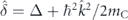 describes the k-dependent exciton–photon detuning. We neglect a dependence on k of the energy of excitons and choose it as a reference. Δ is a constant detuning component. mC is the effective mass of cavity photons,
  is the polariton quasimomentum operator,
  .
.  is the k-dependent splitting of the polariton branches, VR/2 is the vacuum Rabi energy.
  is the 2 × 2 identity matrix.
We describe the polariton quantum state with the spinor wave function ![$\vert {\Psi}\rangle ={\left[{{\Psi}}_{+}\left(\mathbf{r}\right),{{\Psi}}_{-}\left(\mathbf{r}\right)\right]}^{\mathrm{T}}$](https://content.cld.iop.org/journals/1367-2630/22/8/083059/revision2/njpaba731ieqn7.gif) , where Ψ+(−)(r) characterize right-circularly (left-circularly) polarized polariton states. We introduce the three-dimensional pseudospin operator
, where Ψ+(−)(r) characterize right-circularly (left-circularly) polarized polariton states. We introduce the three-dimensional pseudospin operator  , where
  is the vector of the Pauli operators. The second term in the Hamiltonian (1) is responsible for SOI of polaritons. The contributions from both the photon and exciton fractions give rise to the effective magnetic field
  , which causes precession of the polariton pseudospin. The effective field
  comes from the cavity photon fraction of the polariton state and originates from the TE–TM splitting of the cavity modes:
 ![${\hat{\mathbf{\Omega }}}_{\mathrm{C}}=\left[\beta {\hat{C}}_{\hat{k}}^{2}\left({\hat{k}}_{x}^{2}-{\hat{k}}_{y}^{2}\right),2\beta {\hat{C}}_{\hat{k}}^{2}{\hat{k}}_{x}{\hat{k}}_{y},0\right]$](https://content.cld.iop.org/journals/1367-2630/22/8/083059/revision2/njpaba731ieqn12.gif) , where β is the splitting constant,
, where β is the splitting constant,  is the Hopfield coefficient which determines the photon fraction in the polariton state.
Another component  of the effective magnetic field
  determined as
 ![${\hat{\mathbf{\Omega }}}_{\mathrm{X}}=\left[\eta {\hat{X}}_{\hat{k}}^{2}\left({B}_{x}^{2}-{B}_{y}^{2}\right),2\eta {\hat{X}}_{\hat{k}}^{2}{B}_{x}{B}_{y},0\right]$](https://content.cld.iop.org/journals/1367-2630/22/8/083059/revision2/njpaba731ieqn16.gif) describes the contribution of the external in-plane magnetic field B = (Bx, By, 0) affecting the exciton fraction of polaritons. The splitting constant η results from magnetic-field-induced mixing of bright and dark exciton states and is a characteristic of the considered structure [16–18, 24]. The weighting Hopfield coefficient for the exciton fraction is
describes the contribution of the external in-plane magnetic field B = (Bx, By, 0) affecting the exciton fraction of polaritons. The splitting constant η results from magnetic-field-induced mixing of bright and dark exciton states and is a characteristic of the considered structure [16–18, 24]. The weighting Hopfield coefficient for the exciton fraction is  , herewith
  . Figure 1(b) shows the dispersion of the spin-split exciton polariton modes calculated accounting for both photonic and excitonic splittings.
Using the generalized commutation relations, we arrive at the equations for the trajectory operators

The precession equation for the pseudospin operator preserves its form  given in [12, 25] regardless the form of the effective magnetic field operator
  .
.
We take the polariton wave function as |Ψ⟩ = Ψ(r)|ψ⟩, where the function ![${\Psi}\left(\mathbf{r}\right)={\mathfrak{F}}^{-1}\left[{\Psi}\left(\mathbf{k}-{\mathbf{k}}_{0}\right)\right]$](https://content.cld.iop.org/journals/1367-2630/22/8/083059/revision2/njpaba731ieqn21.gif) is responsible for the spatial envelope, and the spinor
is responsible for the spatial envelope, and the spinor ![$\vert \psi \rangle ={\left[{\psi }_{+},{\psi }_{-}\right]}^{\mathrm{T}}$](https://content.cld.iop.org/journals/1367-2630/22/8/083059/revision2/njpaba731ieqn22.gif) describes the polarization state.
describes the polarization state.  is the inverse Fourier transform operator. To reveal the zitterbewegung of the polariton wave packet, we now take the same particular conditions as in [12]. We consider the circularly polarized wave packet, |ψ⟩ = (1, 0)T, propagating ballistically in y direction, k0 = (0, k0). We also take the external magnetic field applied in x direction, B ↑↑ x, i.e. we assume Bx = B, By,z = 0. In the quasi-classical limit applicable, where the spectrum of the wave packet Ψ(k − k0) centered at k0 is narrow, we obtain the trajectory
 ![$\left[X\left(t\right),Y\left(t\right)\right]=\left[\langle \hat{x}\rangle ,\langle \hat{y}\rangle \right]$](https://content.cld.iop.org/journals/1367-2630/22/8/083059/revision2/njpaba731ieqn24.gif) of the polariton wave packet in the form:
of the polariton wave packet in the form:

while the polarization vector evolves as ![$\mathbf{S}\left(t\right)=\langle \hat{\mathbf{S}}\rangle ={\left[0,-\mathrm{sin}\left({\hslash }^{-1}{{\Omega}}_{x0}t\right),\mathrm{cos}\left({\hslash }^{-1}{{\Omega}}_{x0}t\right)\right]}^{\mathrm{T}}$](https://content.cld.iop.org/journals/1367-2630/22/8/083059/revision2/njpaba731ieqn25.gif) . Ωx0,y0 characterize the components of the effective magnetic field Ω0 affecting the polariton propagation. The latter can be obtained from
. Ωx0,y0 characterize the components of the effective magnetic field Ω0 affecting the polariton propagation. The latter can be obtained from  by substituting
  . Thence


In (4),  is the effective mass of polaritons. In the absence of the external magnetic field (B = 0), the amplitude of the zitterbewegung A = Ω'y0/Ωx0 simplifies to A = 2/k0. Subsequently assuming
  constant one can reduces this result to one obtained in [12] in the effective mass approximation.
The color maps in figure 2 show the estimated from (4) dependencies of the amplitude A (figure 2(a)) and the spatial period L (figure 2(b)) of the zitterbewegung on the magnitude of the external magnetic field B and the propagation wave number k0 for a fixed value of β = 140 μeV μm2. The other parameters used for calculations are given in the next section. As one can see, there is a Λ-shape region on the phase plane k0–B, when the amplitude A of the zitterbewegung is considerable and, in theory, can be infinitely large. It happens when the TE–TM splitting and the anisotropic splitting are of the same order and tend to compensate each other, so the component of the effective field Ωx0 (5a) tends to zero. The dash-dotted curves in figure 2 denote the parametric dependence of the parameters Bc(kc) for which Ωx0 = 0. At the same time, with the increase of A, the period of oscillations L ∝ Ωx0 increases proportionally and tends to the singularity in the same conditions, see figure 2(b). Conversely, when the period L is small enough for observing the zitterbewegung, e.g. at k0 close to zero, its amplitude is negligibly small, which makes the oscillations indistinguishable. Nevertheless, there exist regions in the phase plane with the parameters, for which the amplitude of the zitterbewegung remains considerably large (of several micrometers) at reasonably small periods (several hundreds of micrometers).
Figure 2. Characteristics of the zitterbewegung of exciton–polaritons in the quasi-classical limit. (a) The amplitude A and (b) the period L of the zitterbewegung as functions of the magnitude of the external magnetic field B and the wave number k0 of polariton propagation estimated in the quasi-classical limit from (4). The cavity TE–TM splitting constant is taken as β = 140 μeV μm2. The other parameters are the same as in figure 1. The color schemes for the panels (a) and (b) are chosen such that the preferable values of the parameters (larger A and smaller L) belong to the red spectral range. The dash-dotted curves (black in (a) and white in (b)) indicate the singularity in the parameters achieved at ΩC = ΩX for the k0 polariton state. The gray equivalue contours on the color maps are the guide for the eye.
Download figure:
Standard image High-resolution image3. The numerical model for simulating the zitterbewegung
The discussion above is valid for a ballistically propagating polariton in the k0 state. However, the finiteness of the spectrum of a polariton wave packet as well as non-conservative processes accompanying the polariton evolution significantly affect the phase diagrams on the phase plane k0–B. To describe the zitterbewegung in experimentally realizable conditions, we numerically solve the generalized Pauli equation in the basis of right- and left-circular polarizations, ![$\vert {\Psi}\rangle ={\left[{{\Psi}}_{+}\left(t,\mathbf{r}\right),{{\Psi}}_{-}\left(t,\mathbf{r}\right)\right]}^{\mathrm{T}}$](https://content.cld.iop.org/journals/1367-2630/22/8/083059/revision2/njpaba731ieqn30.gif) :
:

where we take into account non-conservative gain and loss processes. The operator 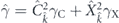 is responsible for the polariton decay rate which in general case is k-dependent, γC and γX are the decay rates of cavity photons and QW excitons. Polaritons are created by the resonant probe |F⟩ = F(r)|f⟩, where the function F(r) is taken in the Gaussian form
 ![$F\left(\mathbf{r}\right)\propto \mathrm{exp}\left[-{\mathbf{r}}^{2}/\left(2{w}_{\mathrm{p}}^{2}\right)\right]\mathrm{exp}\left[\mathrm{i}\left({\mathbf{k}}_{\mathrm{p}}\mathbf{r}-{\omega }_{\mathrm{p}}t\right)\right]$](https://content.cld.iop.org/journals/1367-2630/22/8/083059/revision2/njpaba731ieqn32.gif) , kp and ωp are the wave vector and the frequency of the probe, respectively, wp is the width of the probe spot. In further simulations, we take kp and ωp not independently, but matching the polariton dispersion. The vector
, kp and ωp are the wave vector and the frequency of the probe, respectively, wp is the width of the probe spot. In further simulations, we take kp and ωp not independently, but matching the polariton dispersion. The vector  characterizes the polarization of the probe.
To support formation of the polariton condensate, we introduce the non-resonant optical pumping of polaritons via the reservoir of excitons [12, 32]. The operator ![$\hat{R}=R\left[{n}_{\mathrm{R}+}\left(t,\mathbf{r}\right)\left({\hat{\sigma }}_{0}+{\hat{\sigma }}_{z}\right)+\right.\left.{n}_{\mathrm{R}-}\left(t,\mathbf{r}\right)\left({\hat{\sigma }}_{0}-{\hat{\sigma }}_{z}\right)\right]/2$](https://content.cld.iop.org/journals/1367-2630/22/8/083059/revision2/njpaba731ieqn34.gif) describes the inflow from the reservoir to the polariton state due to the stimulated scattering with the rate R. nR±(t, r) are the densities of the reservoir excitons of the corresponding polarizations. The evolution of the reservoir described by the spinor
describes the inflow from the reservoir to the polariton state due to the stimulated scattering with the rate R. nR±(t, r) are the densities of the reservoir excitons of the corresponding polarizations. The evolution of the reservoir described by the spinor ![$\vert {n}_{\mathrm{R}}\rangle ={\left[{n}_{\mathrm{R}+}\left(t,\mathbf{r}\right),{n}_{\mathrm{R}-}\left(t,\mathbf{r}\right)\right]}^{\mathrm{T}}$](https://content.cld.iop.org/journals/1367-2630/22/8/083059/revision2/njpaba731ieqn35.gif) obeys the rate equation
obeys the rate equation

where the operator Ŵ describing the outflow from the reservoir can be obtained from  by replacing nR±(t, r) → |Ψ±(t, r)|2.
  describes the non-resonant pumping of the exciton reservoir. The pump is considered spatially homogeneous and working in the so-called 'dark regime', when the pump power does not exceed the threshold power P± < Pth, Pth = γγX/R (γ without a hat is given in k space), so it does not lead to the appearance of the polariton condensate. Considering the case of a low-intensity probe and pump, we assume the system to be in a linear regime. The effect of nonlinearity on the zitterbewegung will be the subject of a separate study. In the model we neglect the energy relaxation of polaritons caused by the effect of the reservoir [33], as due to the low density of polaritons and reservoir excitons it is expected to weakly affect the manifestation of the zitterbewegung.
For our simulations, we use the following values of the parameters. The polariton dispersion is obtained from the dispersion of photons with the effective mass mC = 5 × 10⁻⁵me, where me is the free electron mass, and the exciton energy, resonant to the bottom of the photon dispersion, Δ = 0. The Rabi splitting is VR = 5 meV. The constant of the magneto-induced splitting is taken as η = 1 μeV T−2. The photon and exciton decay rates are taken γC = 0.02 ps−1 and γX = 0.025 ps−1, respectively. The scattering rate is taken as ℏR = 0.05 meV μm2. The resonant probe is taken right-circularly polarized as |f ⟩ = (1, 0)T. The non-resonant pump power is taken linearly polarized with P± = 0.95Pth.
4. The zitterbewegung of polariton wave packets
To trace the effect of the external in-plane magnetic field of the zitterbewegung of polariton wave packets in experimentally realizable conditions, we perform a set of 1600 numerical experiments with different values of the parameters kp and B. Here the wave number of the probe kp is used instead of k0. The width of the probe spot is taken as wp = 10 μm. The TE–TM splitting constant is taken as β = 140 μeV μm2. Figure 3 summarizes the results of the simulations and shows the variation of the amplitude A (figure 3(a)) and the period L (figure 3(b)) of the zitterbewegung in the phase plane kp–B. Since the amplitude of oscillations of the trajectory of the polariton wave packet of a finite width decays with the increase of the distance from the injection spot, for the amplitude A of the zitterbewegung, we take the maximum deviation of the trajectory in x direction on the first period of oscillations. For the ease of comparison, the ranges of values of kp and B are taken the same as those in figure 2. Due to the limitations of our numerical experiment caused by the finite size of the computational grid, we were unable to estimate the parameters A and L in the case where the period L was large compared to the size of the calculation area. We shaded the corresponding regions in white (in figure 3(a)) an dark blue (in figure 3(b)). A very good qualitative agreement in figures 2 and 3 shows that the main conclusions made for the quasi-classical limit apply to real polariton wave packets. For the period L of the zitterbewegung, even the quantitative agreement is remarkable. Far enough from the singularity curve, the discrepancy in the numerical estimations and the analytical predictions hardly exceeded 10%. As for the amplitude A of the zitterbewegung, according to figure 3, it is considerably smaller than that in the quasi-classical limit. The discrepancy reaches tens of percent and it is the larger, the closer the parameters (kp, B) are to the critical values (kc, Bc).
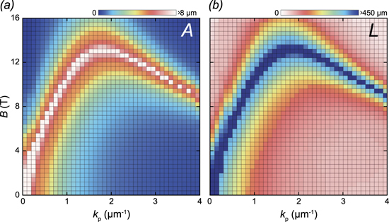
Figure 3. Characteristics of the zitterbewegung of exciton–polaritons in experimentally realizable conditions. (a) The amplitude A and (b) the period L of the zitterbewegung as functions of the magnitude of the external magnetic field B and the wave number kp of the probe estimated from the numerical simulations of (6). The width of the spot of the probe is taken wp = 10 μm. Each square on the color maps corresponds to a single numerical experiment. The squares are colored in white in (a) and dark blue in (b) for the numerical experiments, when we were unable to estimate values of the parameter due to calculation limitations. Values of the parameters used for simulations are given in the text.
Download figure:
Standard image High-resolution imageAs one can see from figure 3, under the in-plane magnetic field, the zitterbewegung becomes observable at large wave numbers even above the inflection point of the polariton dispersion. For the used parameters, for polaritons propagating in y direction, the dispersion possesses the inflection point at kinfl ≈ 1.61 μm−1 and ℏωinfl ≈ −1.7 meV. To illustrate the effect of the external magnetic field on the zitterbewegung, in figures 4(a)–(f), we show the spatial distribution of the density of the polariton condensates I = Ψ†(r)Ψ(r) in the steady state at different values of the magnetic field magnitude B. We take the probe such that it creates polaritons above the inflection point, in particular, kp = 2 μm−1 and ℏωp ≈ −1.4 meV. The most remarkable peculiarity of all the plots is a much weaker spreading of the polariton wave packet in comparison with one discussed in [12] due to approaching the flatter exciton-like region of the polariton dispersion. The polariton wave packet cross-section preserves its shape and width allowing to observe the zitterbewegung at much larger distances. Figure 4(g) shows the corresponding weighted average trajectories of polaritons X(Y) = ⟨Ψ|x|Ψ⟩x/⟨Ψ|Ψ⟩x, where ⟨...⟩x denotes averaging over x in the steady state. For the convenience of analysis, in figures 4(h) and (i) we show the dependencies of the amplitude A and the period L of the zitterbewegung on B at a fixed value of kp = 2 μm−1. In the considered conditions, the TE–TM splitting matches the magneto-induced splitting at Bc ≈ 13.28 T. Figures 4(g)–(i) confirm the simultaneous increase in the amplitude A and the period L of the zitterbewegung with B approaching Bc. Herewith, the apparently more steep curve in figure 4(i) as compared to figure 4(h) shows that the increase in L is faster than one in A.
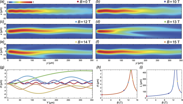
Figure 4. The effect of the external in-plane magnetic field on the zitterbewegung of exciton polaritons. (a)–(f) The effect of the zitterbewegung on the spatial distribution of the density the polariton condensate at different values of the magnitude of the external magnetic field (given in the panels). The polariton condensates were created by the probe beam of width of wp = 10 μm with the wave number of kp = 2 μm−1. (g) The trajectories X(Y) of the centers of mass of the polariton wave packets shown in the panels (a)–(f). (h) The amplitude A and (i) the period L of the zitterbewegung of the polariton wave packet at kp = 2 μm−1 as functions of B. The color markers on the panels (a)–(f) and (h)–(i) indicate the curves of the corresponding color on the panel (g).
Download figure:
Standard image High-resolution imageWe would like to point out that the phase of the zitterbewegung (which is responsible for the direction of deviation of the polariton trajectory along the x axis) is opposite for B < Bc and B > Bc. This is connected to the different orientations of the effective magnetic field Ω(kp) = (Ωxp, 0, 0) at different B which is determined by the sign of the x component  . If the external magnetic field magnitude B is smaller than the critical value Bc, the contribution from the TE–TM splitting exceeds one from the magneto-induced splitting, |ΩC,x| > |ΩX,x| and Ωxp < 0, which results in the effective magnetic field oriented opposite to x direction, Ω(kp) ↑↓ x. If B > Bc, the component Ωxp becomes positive and the effective magnetic field flips, Ω(kp) ↑↑ x. The orientation of the effective magnetic field determines the direction of precession of the polariton pseudospin which affects the phase of the zitterbewegung. More details on the orientation of the effective magnetic field as a function of the magnetic field magnitude and the polariton wave vector are given in the supplementary information (https://stacks.iop.org/NJP/22/083059/mmedia).
When the magnetic field magnitude B is close to Bc, the spatial polariton density distribution deviates from the solid shape and acquires a fork-like shape. To clarify this, in figure 5 we show the spatial distribution of the pseudospin vector components Sj = Ψ†(r)ŜjΨ(r)/I(r) (j = x, y, z) characterizing polarization of the exciton–polariton condensates of the solid shape at B = 10 T (figure 5(a)) and of the fork-like shape at B = 13 T (figure 5(c)). At B = 10 T, the pronounced regular patterns are characteristic to the Sy and Sz components supplemented by wavy patterns in the Sx component. The period of oscillations of the polarization patterns coincides with one of the zitterbewegung. At B = 13 T, the situation dramatically changes. The splitting in linear polarizations is small which causes mixing of the linearly polarized modes. The polarization plane of the polariton states rotates as a result of this mixing, herewith the direction of rotation is kx-dependent. In figure 5(c) on the color map for the diagonal component Sy, instead of oscillations in y direction we observe the separation in x direction of the Sy > 0 and Sy < 0 polarizations reflected in the fork-like shape of the polariton density distribution. With B approaching the critical value Bc, the separation of opposite diagonal polarizations becomes more pronounced, while the contribution of Sx and Sz diminishes. The color maps of polarization components for all polariton condensates shown in figure 4 are given in the supplementary information.
Figure 5. The effect of the zitterbewegung on the polarization properties of polariton wave packets. Spatial distribution of the polartization components of the exciton–polariton condensates at (a) B = 10 T and (b) B = 13 T.
Download figure:
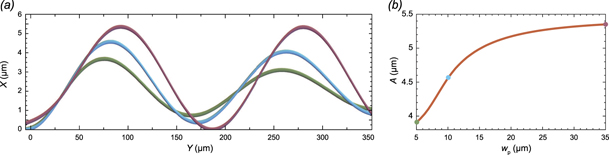
Standard image High-resolution imageAs we mentioned earlier, the amplitude of the zitterbewegung of the polariton wave packet of the finite width is smaller than one in a quasi-classical limit. Figure 6 illustrates the effect of width of the probe beam wp on the zitterbewegung of polaritons. Center-of-mass trajectories X(Y) of polaritons are plotted for wp = 5 μm (green curve), wp = 10 μm (blue curve) and wp = 35 μm (crimson curve) in figure 6(a) at B = 12 T. The other parameters are the same as for figure 4. The increase in width of the polariton wave packet brings the system closer to the quasi-classical limit. This results in the increase in the amplitude A of the zitterbewegung with the increasing width of the probe wp, as shown in figure 6(b). Remarkably, the period of the zitterbewegung is hardly affected by the width of the probe.
Figure 6. The effect of the width of the probe beam on the zitterbewegung of exciton polaritons. (a) The trajectories X(Y) of the centers of mass of the polariton wave packets at different values of the width of the probe beam: wp = 5 μm (green curve), wp = 10 μm (blue curve) and wp = 35 μm (crimson curve). (b) The amplitude A of the zitterbewegung of the polariton wave packet at kp = 2 μm−1 and B = 12 T as a function of wp. The color markers in (b) indicate the curves of the corresponding color in (a).
Download figure:
Standard image High-resolution image
5. Discussion
In this paper, we have proposed the approach to enhancing and controlling the effect of the zitterbewegung of exciton polaritons, which consists in the appearance of the perceptible displacement of polaritons in the direction perpendicular to the direction of their propagation. Taking advantage of the composite nature of exciton–polaritons, we act upon their excitonic component with the external magnetic field in order to control the period and the magnitude of oscillations of their trajectories. When moving along the polariton dispersion surface with the increasing wave vector, the contribution of the cavity photons to the polariton state diminishes being replaced by the contribution of excitons in QWs. The zitterbewegung effect of a purely photonic origin is visible only for exciton polaritons with wave vectors close to zero or sufficiently below the inflection point of the low-polariton dispersion branch [12]. The interplay between exciton and photon polarization splitting that appears in the presence of the in-plane magnetic field makes possible the observation of this important effect for polaritons with large wave vectors even above the inflection point.
The splitting of linearly polarized exciton states may be originated by the reduced translational or point symmetry of QWs or their interfaces. In this manuscript, only the magnetic-field-induced splitting of excitons was considered. Among other possible mechanisms of the splitting are the exchange induced anisotropy [34, 35], the reduced symmetry of the QW interfaces in comparison with the bulk crystal that leads to the appearance of an internal electric field. This field mixes heavy holes, which are in the basis of optically excited polaritons, and light holes, herewith the splitting in energy is characteristic to the new mixed states. The symmetry breaking can be inherent to the structure due to, e.g. an acquired strain at the stage of growth, the built-in electric field of roughness of interfaces [36–38]. The magnitude of the splitting in this case as a rule amounts of tens of microelectron volt. The strain-induced splitting of 100 μeV was demonstrated in [39]. The heavy-light hole mixing can also been provoked by an external impact. In [40], the authors apply stress to the sample and achieve impressive values of the splitting of exciton states of up to 1 meV in specific conditions. Nevertheless, the magnetic-field-induced splitting remains dominant in comparison with most of these mechanisms.
We would like to comment on the observability of the polariton zitterbewegung. Exciton–polaritons possess a finite lifetime which strongly bounds their propagation distance. Recent achievements in engineering of dielectric microcavities allow exciting polaritons characterized by lifetimes of the order of hundreds of picoseconds and propagating by the distances over 1 mm in the cavity plane [41–43]. However, these significant propagation distances are characteristic of photon-like polaritons. In our manuscript, we focus on exciton-like polaritons whose lifetime cannot exceed tens of picoseconds, realistically. To increase the distance of the macroscopic spreading of polaritons, we propose taking advantage of the stimulated scattering of excitons from the reservoir to the polariton mode [32]. The reservoir is conveniently created by a non-resonant optical pumping in the sub-threshold regime. This enables observing the polariton zitterbewegung over several periods of spatial oscillations. The presence of the exciton reservoir may trigger the energy relaxation of the polariton condensate [33]. This effect is expected to amplify the decay of the amplitude of oscillations with distance. Nevertheless, the zitterbewegung of polaritons remains observable. In the case of the resonant pumping alone, the spreading distance of the macroscopic polariton wave packet is strongly limited by the finite lifetime of propagating polaritons and hardly reaches several tens of micrometers. The color maps in figure 3 show that the system can be tuned to the conditions allowing for the observation of full-period oscillations even at such a small spreading distance. If the period of oscillations significantly exceeds the polariton propagation length, the effect of the zitterbewegung can be identified as the deviation of the wave packet trajectory from the linear ballistic trajectory. Still, these traces of the zitterbewegung are far less impressive than the long oscillating trajectories expected in the case of a combined resonant and non-resonant pumping (see figure 4).
The observation of the zitterbewegung of exciton–polaritons is of a fundamental importance as it gives the opportunity to observing the manifestation of a purely quantum mechanical phenomenon on a macroscopic scale. From the practical point of view, the magnetic control over the characteristics of the zitterbewegung as well as over the polarization properties of the polariton condensate allows considering the system as a polaritonic analog of the Datta-and-Das spin transistor [19, 44, 45]. The ability of separating in space of orthogonal linear diagonal polarizations allows one to use the proposed system as a polariton rectifier of the cw light.
Acknowledgments
This work is from the Innovative Team of International Center for Polaritonics and is supported by Westlake University (Project No. 041020100118). ES and AK acknowledge the support from the Program 2018R01002 funded by Leading Innovative and Entrepreneur Team Introduction Program of Zhejiang. ES and IS acknowledge support from the Grant of the President of the Russian Federation for state support of young Russian scientists (No. MK-2839.2019.2). AK acknowledges the Saint Petersburg State University for research Grant ID 51125686.