


Abstract
A novel multilayer terahertz metamaterial composed of double rectangle, vertical single rectangle, vertical double rectangle and single rectangle graphene layer is proposed. The dynamic adjustable triple plasmon induced transparency (PIT) is realized by coupling two bright modes and two dark modes, which is an especial synergy effect between two single-PIT. Coupled mode theory contained four resonators is employed to explain the triple-PIT, and the theoretical results exhibit excellent consistency with finite-difference time-domain. Surprisingly, the triple-PIT can evolve into a dual-PIT or a single-PIT only by changing the Fermi level of graphene, and the amplitude modulation degrees at the four resonance frequencies of the triple-PIT are 74.7%, 87.8%, 76.5%, and 77.7%, respectively. In addition, a simultaneous switching at multiple frequencies is realized by adjusting different Fermi levels. Therefore, this study not only lays the foundation for explaining phenomenon of the triple-PIT but also puts forward new ideas for the design of optoelectronic device.
Export citation and abstract BibTeX RIS

Original content from this work may be used under the terms of the Creative Commons Attribution 4.0 licence. Any further distribution of this work must maintain attribution to the author(s) and the title of the work, journal citation and DOI.
1. Introduction
Recently, more and more attention has been paid to the generation of surface plasmon polaritons (SPPs) on graphene [1, 2]. The main reasons are that graphene is easy to edit, adjustable by voltage and highly conductive, and the properties of the SPPs generated on graphene are superior to that on metal [3, 4]. The plasmon-induced transparency (PIT) is generated by the SPPs, whose formation mechanism is the resonance interaction between the bright and dark mode. Compared with electromagnetic induced transparency (EIT) [5, 6] generated in system by atomic coherence, the PIT has the advantages of lower experimental requirements. Therefore, the advantages of using graphene to induce plasmonic transparency window are obvious.
The single-PIT is formed by interaction between a bright and a dark mode. The bright mode, which can be excited by the incident light directly, reduces the transmission and generates a Lorentz line in the transmission spectrum owing to localizing the light field around the structure. The dark mode is not excited by the incident light directly, which cannot produce obvious variety in the transmission spectrum. However, the dark mode can be excited by the light field produced by interaction between the incident light and the bright mode. The two modes reach resonance at some frequencies, which produces two transmission valleys and a PIT window. For the study of PIT, the single-PIT is realized in not only single-layer structure [7, 8] but also multi-layer structure [9]. Further, the dual-PIT is produced by the interaction of three resonant modes including two bright modes and a dark mode. Similarly, the dual-PIT can be realized in single-layer [10, 11] or multi-layer structure [12]. However, the study about how to realize triple-PIT is still rarely reported. In addition, most studies about the evolution from single-PIT to dual-PIT ignore an intermediate process, which is extremely important phenomenon called synergy effect.
In this paper, a silica–silicon–silica sandwich-structure multilayer terahertz metamaterial is proposed, which realizes a triple dynamic tunable PIT by the interference superposition among two bright modes and two dark modes. Coupled mode theory (CMT) are employed to explain the triple-PIT, and the theoretical results of the triple-PIT are fitting with finite-difference time-domain (FDTD) [13]. We have found that the triple-PIT is formed by an especial synergy effect between two single-PITs. The evolution of the triple-PIT to the dual-PIT or the single-PIT is explored by modulating the Fermi level of graphene with voltage. More importantly, the amplitude modulation degrees have been obtained at the four resonance frequencies of the triple-PIT in the process of evolution, which can be 74.7%, 87.8%, 76.5% and 77.7%, respectively. Surprisingly, a simultaneous switching at multiple frequencies is realized. Based on the above discussion, our proposed structure provides a theoretical basis for the triple-PIT and the design of optoelectronic device [14–18].
2. Structure and theoretical model
The structure shown in figure 1(a) is a unit of the metamaterial composed of three graphene-layers, which are connected by three electrodes on a flat silica and silicon substrate. Here, the electrodes are applied with a gate voltage for indirect modulation of the graphene Fermi level. The upper-layer graphene (ULG) is a double-rectangle graphene strips; the middle-layer graphene (MLG) is a vertical single-rectangle graphene strip consisting of a vertical double-rectangles and a vertical single-rectangle; the lower-layer graphene (LLG) is a single-rectangle graphene strip. The top view is shown in figure 1(b), whose geometric parameters are as follow: l1 = 1.6 μm, l2 = l6 = 0.4 μm, l3 = 2.6 μm, l4 = l5 = 0.8 μm, l7 = 2.4 μm, Lx = Ly = 4 μm, h1 = h2 = h3 = h4 = 0.1 μm. The substrates of top and bottom layers are silica, whose advantage is to prevent the oxidation reaction of the structure and improve the stability of the structure. The substrate of middle layer is silicon.
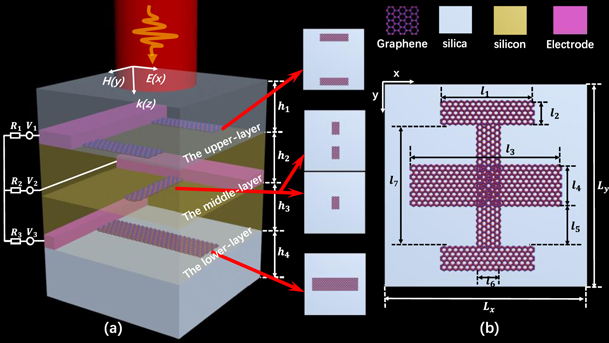
Figure 1. (a) Schematic diagram of a patterned graphene metamaterial. (b) Top view of a patterned graphene metamaterial.
Download figure:
Standard image High-resolution imageWhen the structural unit is shone vertically by the x-polarized light, the four structures can produce two bright modes and two dark modes. Here, the bright modes are played by the ULG and the LLG; the MLG act as two dark modes. The spectra formed in different structures are plotted in figure 2. As shown in figure 2(a), the ULG acted as the bright mode produces a green Lorentz curve. The double-rectangle of the MLG acted as the dark mode cannot directly interact with the incident light field, which produces a black curve. The interaction of the two structures produces a violet curve of single PIT, which is marked as PIT1. In figure 2(b), the green Lorentz curve is generated by the LLG acted as the bright mode, where the dark mode is played by the single-rectangle of MLG. The interaction of the two structures produces a red curve of single PIT, which is marked as PIT2. In many studies, [19–21] the polarization direction of the light source has a great influence on the results. However, the change of the polarization direction of the incident light will have a destructive effect on the phenomenon of PIT. Thus, the condition of changing the polarization direction is not considered.
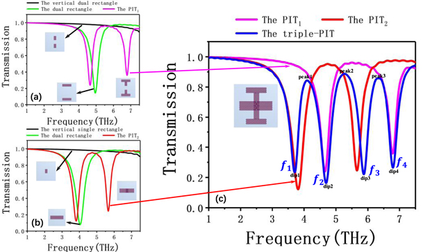
Figure 2. (a) and (b) Transmission spectra of the different arrays. (c) Transmission spectra of the four patterned graphene metamaterials. Here, the Fermi level is set to 1.0 eV.
Download figure:
Standard image High-resolution imageSurprisingly, when two bright modes and two dark modes are coupled with each other, the phenomenon of triple-PIT is appeared in figure 2(c). From the number of resonance modes, we know that each single PIT has two resonance modes and two noninteracting single PIT has four resonance modes. Under normal circumstances, the coupling of two single PITs only produces a dual-PIT, because two adjacent modes among four resonance modes can be coupled to form a new one and disappeared, which is a phenomenon that one plus one equals two. However, if there is a certain difference phase between two single PITs, the coupling cancellation between adjacent resonant modes will no longer occur, and the unchanged number of resonance mode is maintained at four. In this case, two interacting single PITs result a phenomenon of triple-PIT. Here, PIT2 is divided into peak1 and peak2, and PIT1 is divided into peak2 and peak3. Among them, peak1 has the same physical characteristics as PIT2, which is affected by the LLG acted as the bright mode. Peak3 is same as PIT1, which is influenced by the ULG acted as the other bright mode. Peak2 comes from the superposition of PIT1 and PIT2, which is affected by two single PITs. In short, the triple-PIT is generated by synergy effect between two single-PIT, which is a phenomenon that one plus one is greater than two.
In order to clearly interpret the physical insights, the field distributions of each layer at the four resonance frequencies are plotted, as shown in figure 3. The electric field of f1 is mainly distributed on the LLG indicating that LLG is the bright mode, where dip1 is mainly affected by the LLG as shown in figure 3(a). But it should be noted that the excited structure is not only affected by the LLG but also the single-rectangle of MLG, where the single-rectangle of MLG plays a related role. Similarly, the ULG acts as the bright mode, because it can be excited by the incident light, which can be seen clearly from the electric field energy of f2 localized around the ULG in figure 3(b). As shown in figure 3(c), the electric field is concentrated on the single-rectangle of MLG at f3, the single-rectangle of MLG acts the dark mode, which is excited by the interaction between the incident light and the LLG. Finally, the double-rectangle of MLG (acts as the dark mode) is excited by the interaction between the incident light and the ULG at f4, which is implied by the fact that the field energy is localized in the double-rectangle of MLG in figure 3(d). These electric fields are consistent with the bright and dark modes discussed above.

Figure 3. (a)–(d) Electric field distribution of the whole structure at different layers. Here, the Fermi level is set to 1.0 eV.
Download figure:
Standard image High-resolution image3. Math method
CMT (coupled mode theory) [22, 23] in figure 4 is employed to further explain and analyze the triple-PIT phenomenon. 'A, B, C, D' are four imaginary resonators corresponding to two bright modes and two dark modes, whose amplitudes are denoted by 'a, b, c, d'. The superscript in/out and the subscript ± of "A±in/out, B±in/out, C±in/out, D±in/out" represent input or output waves and positive or negative direction of waves propagating, respectively. The mutual coupling coefficients of the four resonators are denoted by μmn (m = 1, 2, 3, 4, n = 1, 2, 3, 4, m ≠ n). There is an opposite relationship between h2 and μ1n (n = 2, 3). The larger h2 is, the smaller μ1n are. So are the other mutual coupling coefficients.

Figure 4. Schematic diagram of coupled mode theory.
Download figure:
Standard image High-resolution imageFirstly, the conductivity of graphene can be obtained by [24]:

where τ = μEf/eVF2 is the carrier relaxation [25], with i.e., Ef, ℏ, ω, μ, VF being the imaginary unit, the electronic charge, the Fermi level of graphene, the reduced Planck constant, the angle frequency of incident light, the mobility of graphene, and the Fermi carrier velocity with a value of 106 m s−1 [26], respectively.
Because the substrates is different, the formula for the propagation constant of the middle layers can be expressed as [27, 28]:

The other formula for the propagation constants of the upper and lower layers can be expressed as: [29]

here, εSi, εSiO2, ε0, η0, k0 are the relative permittivity of silicon, the relative permittivity of silica, the relative permittivity of air, the inherent impedance, and the wave vector, respectively. The inherent impedance is η0 = (μ0/ε0)1/2, in which μ0 is the permeability of vacuum. The inter-loss quality factor Qin is got from Qin = Re(neff)/Im(neff) [30, 31] with neff = β/k0 being the effective refractive index.
The quality factor of the entire system called total-loss quality factor is got from Qtn = f/Δf, where f and Δf are the resonant frequency and the full width at half maxima (FWHM) of transmission spectrum, respectively. Moreover, with ωn being the nth resonant angular frequency, γin and γon calculated by γin = ωn/2Qin and γon = ωn/2Qon represent their inter-loss and extra-loss coefficient, respectively. The extra-loss coefficient γon can be got from γon = ωn/2Qtn − ωn/2Qin obtained by 1/Qtn = 1/Qin + 1/Qon [32].
Secondly, the relationship between the four modes can be expressed as:
where γn = iω − iωn − γin − γon (n = 1, 2, 3, 4).
When a plane wave is injected from A and emitted from D, the wave of four resonant modes system is only injected from A. The condition can be described by:

Based on the conservation of energy, the relationships of energy are as follows:


where, φ1, φ2, and φ3 refer to the phase difference between A and B, B and C, C and D, respectively. φn (n = 1, 2, 3) can be obtained from the formula φn = Re(β)dn = ωdnRe(neff)/c, in which dn is the distance between graphene layers.
According to equations (4)–(12), the transmission coefficients of the entire system can be obtained by:

the equation satisfied by the coefficients Da, Db, Dc, and Dd are as follows:

where,


Thus, the transmission can be obtained by T = │t│2.
4. Results and application
Most of study have shown that the Fermi level of graphene can be modulated by the appropriate gate voltage as follows [33]:

in which, Vg and h are the gate voltage and the thickness of silicon. As the Fermi level increases from 0.9 eV to 1.2 eV by a step of 0.1 eV, the transmission spectra of FDTD numerical simulations are shown as blue curves in figure 5(a), which are consistent with the CMT results shown as red curves marked by x. The transmission spectra almost linearly show blue shift as the Fermi level increases, the 3D planar diagram of the evolution can be seen apparently, which is plotted in figure 5(b). The above point reveals that the triple-PIT is dynamically adjustable.

Figure 5. (a) Transmission spectra obtained by FDTD simulation and CMT calculation at different Fermi levels. (b) 3D planar diagram of the evolution of the triple-PIT.
Download figure:
Standard image High-resolution imageThe above discussions of dynamic modulation are based on the simultaneous change of Fermi energy levels for all three graphene-layers. Next, one or two Fermi levels are changed to observe the evolutionary mechanism of PIT, and we found that two single-PITs with certain phase difference can couple by different ways. First of all, the triple-PIT can evolve into the dual-PIT, as shown in figure 6(a). As the Fermi level of LLG decreases from 1.0 eV to 0.5 eV, a red shift phenomenon in PIT2 is appeared. Meanwhile, the phase difference between two single-PITs increases gradually. The triple-PIT eventually evolves into the dual-PIT, where the synergistic effect disappeared. The evolutionary process is plotted in figure 6(c). Further, with the phase difference of two single PITs decreases to zero approximately by modulating the Fermi levels of the ULG and LLG, the triple-PIT can evolve into the single-PIT as shown in figure 6(b). The evolutionary process is plotted in figure 6(d), here, we consider the Fermi levels of the two structures as a whole condition. Thus, the triple-PIT called synergistic effect is the intermediate process of mutual evolution between the single-PIT and the dual-PIT.

Figure 6. (a) and (b) Schematic diagram of evolution from the triple-PIT to the dual-PIT or the single-PIT. (c) and (d) 3D planar diagram of the evolution of the triple-PIT.
Download figure:
Standard image High-resolution imageCompared the triple-PIT with the dual-PIT, the evolutionary result is plotted in figure 7(a), where it has significant difference in transmission at f1 and f3. The modulation degree of amplitude is used to described variation, which can be calculated by [34]:

where A1' and A1 are the transmission amplitudes. When the Fermi levels of all three graphene-layers are set 1.0 eV, the transmission amplitudes at f1 and f3 are 0.234 and 0.222, where is 'off' state. When the graphene Fermi level of LLG is set 0.5 eV and the others are set 1.0 eV, the transmission amplitudes at f1 and f3 are 0.925 and 0.946, which are the 'on' state with the insertion loss of 0.075 and 0.054. Thus, the modulation degrees of amplitude are 74.7% and 76.5% at f1 and f3. So a simultaneous switching at multiple frequencies can be realized and designed. Similarly, comparison between the triple-PIT and the single-PIT is plotted in figure 7(b), where the Fermi levels corresponding to the triple-PIT are set as 1.2 eV for obtaining better effect of optical switch. The modulation degrees of amplitude are 87.8% (0.113, 0.930) and 77.7% (0.213, 0.954) at f2 and f4 with the insertion loss of 0.07 and 0.046, respectively.

Figure 7. (a) The comparison between the triple-PIT and the dual-PIT. (b) The comparison between the triple-PIT and the single-PIT.
Download figure:
Standard image High-resolution image
Therefore, the formation mechanism of the triple-PIT, which is analyzed by the different coupling patterns between two single-PITs, is obtained. In addition, the amplitude can be modulated at four resonance frequencies, whose modulation degrees are 74.7% of 3.707 THz, 87.8% of 5.080 THz, 76.5% of 5.873 THz, and 77.7% of 7.272 THz, respectively. Furthermore, the extinction ratio, which is an important parameter to describe the performance of optical switch, can be obtained by [35]:

where the extinction ratios are 5.97 dB, 9.15 dB, 6.30 dB, and 6.51 dB. And given that the sharpness of the modulator is highly important in defining the performance of the device, therefore the dephasing time, which is given by T = 2ℏ/FWHM [36, 37], is an important parameter. For the four dips, the dephasing time are estimated as 5.489 ps, 4.657 ps, 5.589 ps, and 6.148 ps. Based on that, this work can be used to design the optical simultaneous switching at multiple frequencies.
5. Conclusions
A novel multilayer terahertz metamaterial, which composed of three graphene layers contained the double-rectangle strip, the vertical single-rectangle strip, and the single-rectangle strip, has been proposed. The dynamic adjustable triple plasmon induced transparency (PIT) is realized, which is an especial synergy effect. Coupled mode theory (CMT) are employed to explain the triple-PIT, which are consistent with FDTD simulation. Compared with the other material structures of PIT, this structure has many new discoveries. First of all, the triple-PIT, which is the intermediate process of mutual evolution between the single-PIT and the dual-PIT, can evolve into a dual-PIT or a single-PIT only by changing the Fermi level of graphene. Secondly, the amplitude modulation degrees at the four resonance frequencies of the triple-PIT are 74.7%, 87.8%, 76.5%, and 77.7%. In addition, a simultaneous switching at multiple frequencies is realized by adjusting different the Fermi level. In short, we believe that work will lay the foundation for explaining phenomenon of the triple-PIT and put forward new ideas for the design of optoelectronic device.
Acknowledgments
National Natural Science Foundation of China (No. 11847026, 61764005 and 11804093); the Scientific Project of Jiangxi Education Department of China (No. GJJ160532); the Graduate Education Reform Project of Jiangxi Province of China (No. JXYJG-2017-080); Natural Science Foundation of Jiangxi Province (No. 20192BAB212003).
Conflicts of interest
The authors declare that they have no competing interests.