


Abstract
The ability to create linear systems that manifest broadband nonreciprocal wave propagation would provide for exquisite control over acoustic signals for electronic filtering in communication and noise control. Acoustic nonreciprocity has predominately been achieved by approaches that introduce nonlinear interaction, mean-flow biasing, smart skins, and spatio-temporal parametric modulation into the system. Each approach suffers from at least one of the following drawbacks: the introduction of modulation tones, narrow band filtering, and the interruption of mean flow in fluid acoustics. We now show that an acoustic media that is non-local and active provides a new means to break reciprocity in a linear fashion without these deleterious effects. We realize this media using a distributed network of interlaced subwavelength sensor–actuator pairs with unidirectional signal transport. We exploit this new design space to create a stable metamaterial with non-even dispersion relations and electronically tunable nonreciprocal behavior over a broad range of frequencies.
Export citation and abstract BibTeX RIS
Reciprocity in wave-bearing acoustic media is remarkably robust, especially in linear systems, maintained in viscoelastic solids [1], fluid–structure systems [2], and structural-piezoelectric-electrical coupled systems [3]. Further, as is well-established, anisotropy and inhomogeneity, while generating interesting wave propagation phenomena, do not engender linear nonreciprocity [1]. Acoustic reciprocity, formally introduced by Helmholtz in 1860 (as discussed in [4]) and later generalized by Lyamshev [5] to include fluid–structure interaction and multiple scatterers, dictates that the response to a disturbance is invariant upon interchange of the source and receiver. Fluid and solid acoustic media that break reciprocity over broad frequency ranges would enable new and unexplored forms of control over vibrational and acoustic signals, with enormous implications for spectral filtering and duplexing in the communications industry [6], and noise control [7, 8]. Efforts aimed at achieving nonreciprocity in both linear and nonlinear electromagnetic systems have been particularly successful primarily because of the effectiveness of a biasing magnetic field in devices such as the Faraday isolator [9]. These successes have spurred research in analogous acoustic systems where instead of an external magnetic field, introduction of mean flow in the acoustic medium [10] has been used to achieve a high level, narrowband nonreciprocity. Similarly, biasing in a solid using a DC electric field can result in asymmetric damping and nonreciprocal wave propagation in piezoelectric semiconductors [11, 12] as well as in a two-dimensional electron gas coupled to piezoelectric semiconductors [13]. In magnetoelastic and polar media, a DC magnetic field can lead to nonreciprocal effects, although these nonreciprocal effects are often relatively weak (as discussed in [1, 14]). Other approaches to acoustic nonreciprocity rely on breaking the spatial or temporal symmetry in the governing equations by introducing nonlinear interactions [15, 16] or spatiotemporal modulation of the properties of the medium [17, 18]. Theoretical analysis has shown that spatiotemporal modulation of strongly magnetoelastic materials, like terfenol, and piezoelectric materials, like PZT, can lead to impressive nonreciprocity, as shown in [19]. Both nonlinearity and spatiotemporal modulation introduce secondary tones that require later demodulation or signal processing to prevent signal corruption. To circumvent the disadvantages associated with background bias or spatiotemporal parametric modulation, other studies have utilized sensor–actuator pairs to modulate the wave propagation in the medium in a linear fashion [20–23]. To our knowledge, we are the first to exploit a system with distributed control using non-collocated sensor–actuator pairs to introduce inherent violation of parity and time symmetry through non-local mechanisms, and achieve linear acoustic nonreciprocity.
In our approach, we use an asymmetric unit cell consisting of a sensor and actuator pair, separated from one another by a subwavelength distance dff, as shown in figure 1(a). The pairs are arrayed and interlaced along the length of the waveguide. This arrangement breaks spatial symmetry and creates a preferential direction because information is transmitted nearly instantaneously in a unidirectional fashion from sensor to actuator via a distributed amplifier network, while acoustic disturbances propagate bidirectionally at the much slower group velocity of the waveguide. This non-local active metamaterial (NAM) is similar to the canting of the hair cells and phalangeal processes seen in the mammalian cochlea, a feature hypothesized to play a role in wave amplification and dispersion in the hearing organ [24].
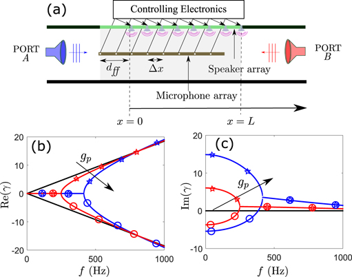
Figure 1. (a) Example configuration of the non-local active metamaterial (NAM) concept applied to an airborne acoustic medium. The sensors (microphones) and actuators (speakers) are arrayed along the waveguide and the output of each sensor is fed forward a distance dff to its corresponding actuator. (b) Real part and (c) imaginary part of the first two root loci of the complex wavenumber solutions to equation (3) for dff = 10 cm, and gp set to three values, 0 m−2 (black), 20 m−2 (red) and 50 m−2 (blue). Colored stars and circles are used to delineate the first and second root loci of the dispersion relation for each non-zero choice of gp.
Download figure:
Standard image High-resolution imageTo illustrate this general NAM concept as a tool to engineer nonreciprocal behavior, we use an airborne acoustic system as shown in figure 1(a), although this paradigm could be adapted for other wave-bearing media, like piezoelectric or magnetoelastic materials, with appropriate electronic control. First we consider the system in the limit where the acoustic wavelength is much larger than the spacing between successive sensors or actuators (Δx) so we can treat the active medium as a continuum. The sensed pressure is fed forward to the monopole sources located at a distance dff downstream. If we assume that the source can be manipulated electronically to precisely match the upstream pressure and that the electronic control is instantaneous, the acoustic source strength can be written as gpp(x − dff), where gp is the open loop gain between the sensor and the actuator. This simplifying assumption will be relaxed later to reflect the dynamics of the acoustic source. With these assumptions, the pressure in the waveguide (p) can be modeled using a modified version of the one-dimensional Helmholtz equation with an additional pressure-proportional source term as

where c is the acoustic speed, ω is the radian frequency (assuming an e−iωt time dependence), and k = ω/c. The gain gp is non-zero for x ∈ (0, L) and is zero elsewhere. To show the nonreciprocity of the NAM, let pI(x) be the solution of equation (1) due to a point source QI at x = x1 and pII(x) the solution due to a point source QII at x = x2, where x1 < 0 and x2 > L. Following standard arguments typically used to prove reciprocity in acoustics [1], we find

so that acoustic reciprocity, given by pII(x1)QI = pI(x2)QII [25], holds only at exceptional frequencies when the left-hand side integral vanishes. The spatial separation of the sensor and the actuator and the unidirectional sensor-signal transmission are the crucial elements in achieving inherent nonreciprocity in the NAM system. This is fundamentally different from the case where active elements of an acoustic waveguide are coupled via a bidirectional transmission line [26], because such a system is reciprocal. The non-local approach is also different from case where the sensor and source are collocated and local impedance modification or bianisotropy is utilized to achieve nonreciprocity [20, 21], because the non-locality, even though subwavelength, affords additional flexibility in achieving nonreciprocity.
To further investigate the nonreciprocal wave characteristics of the NAM, we assume harmonic waves of the form p0eiγx to obtain the dispersion relation in the active region (equation (1)) given by

where γ is the wavenumber. Owing to the exponential term on the right-hand side of (3) there are an infinite number of complex root loci and the equation is not even in γ. In order to show the evolution of the complex wavenumber–frequency loci with increasing gain, we plot the real part of the wavenumber in figure 1(b) and the imaginary part in figure 1(c) for the first two root loci. Two nonzero values of gp are chosen, gp = 50 m−2 (in blue) and gp = 20 m−2 (in red). The nondispersive and purely real wavenumber loci γ(+/−) = ±ω/c of the passive case (gp = 0 m−2) are shown for reference with black lines. For both active loci, the allowed waves are purely evanescent at low frequencies and asymmetric about the ordinate, indicating directionally dependent phenomena. The loci for both choices of nonzero gains exhibit a bifurcation point beyond which both root loci exhibit decay in the left-to-right direction (A → B) and growth in the right-to-left direction (B → A), demonstrating spatial nonreciprocity of the NAM. These gains yielded stable temporal solutions for the unbounded case, as confirmed by simulating the impulse response of the NAM. Increasing the gain changes the asymmetry of the evanescent component of the wavenumber, increases the frequency where the bifurcation point occurs, and eventually results in instability.
To determine if the nonreciprocity seen in the continuous system is conveyed to a system composed of discrete sensors and actuators, we consider an array of N = 10 uniformly spaced pairs (Δx = 5 cm) arranged in the active section in an infinite acoustic duct as shown in figure 1(a). We retain the assumption that the electronics can provide the gain necessary to guarantee that the acoustic source strength of each actuator is equal to the discrete gain, gd, times the measured pressure at a distance dff = 10 cm upstream, similar to the source term in equation (1). We modeled this numerically in two ways. First, we used one-dimensional (1D) acoustic theory, with the actuators idealized as point sources. Second, we used a full-wave (FW) solution that consisted of a complete three-dimensional finite element acoustic model in COMSOL Multiphysics that included the finite extent of the sources, treated as boundary velocity forcing, and three dimensionality of the fluid domain. Parameters for the 1D and FW models are given in the supplemental material. We define the transmission coefficient T as the ratio of the amplitude of the transmitted and the incident pressure field, and the reflection coefficient R as the ratio of the amplitude of the reflected and the incident field, expressed in dB. For a plane wave incident from port A, the subscript A → B is used while the subscript B → A represents the opposite situation. Analytical expressions for these coefficients derived from the 1D model are as follows,
where  , I is an N × N identity matrix, and G is a matrix of Green's functions, with
  denoting the Green's function from the nth source located at x = xsn to the mth sensor probe located at x = xpm. Equation (4) reveals the complex interaction of gd, Δx, and dff that result in nonreciprocal wave transmission through the system. As shown in figure 2(a), TA→B ≠ TB→A over the frequency range plotted (except at a single frequency) resulting in a non-symmetric scattering matrix, demonstrating the nonreciprocal nature of the system [27]. The reflection coefficients (figure 2(b)) are equal in amplitude, |RA→B| = |RB→A| but differ in phase by 2kdff radians (see proof in the supplemental material) (http://stacks.iop.org/NJP/22/063010/mmedia) for our equispaced sensor–actuator system. This is in stark contrast with
  symmetric systems, where the transmission coefficients from either direction are the same and the reflection coefficients differ [28]. Further, if the actuator has sufficient authority to deliver pressure at very low frequencies, this system reflects incoming waves from both directions at those frequencies, acting as a subwavelength wall for sound. Finally, near 1600 Hz, TA→B = TB→A representing a special frequency in the discrete system where reciprocity is restored, a scenario predicted by the reciprocity analysis of the prototypical continuous system (equation (2)). Multiple such special frequencies exist beyond beyond 1600 Hz, between which transmission coefficients oscillate about 0 dB with diminishing amplitude. Due to the presence of the wavenumber k in the denominator in equation (4), at very high frequencies, the system is effectively transparent to impinging waves from either direction. The FW simulations (symbols) are in good agreement with the 1D acoustic theory (solid lines) in this frequency range. The degree of nonreciprocity quantified by the isolation factor IF, defined as the difference of TB→A and TA→B, exceeds 40 dB over a broad range of frequencies from DC up to 800 Hz, as shown in figure 2(c), and displays a 20 dB IF bandwidth of more than 1 kHz. As noted, these impressive nonreciprocal effects diminish with increasing frequency.
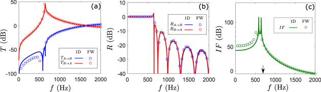
Figure 2. The (a) transmission and (b) reflection coefficients of the discrete realization of the NAM for a wave traveling from port A to B (blue) and from port B to A (red) as obtained from full wave (FW) simulations (symbols) and 1D simulations (solid lines). (c) the IF derived from the A → B and B → A transmission spectra in (a).
Download figure:
Standard image High-resolution imageTo further explore the effectiveness of the NAM, the spatial variation of the real part of the total pressure field due to incidence of 692 Hz plane wave from port A is shown in figure 3(a) and incidence from port B in figure 3(b). This frequency was chosen to establish the efficacy of the NAM away from the maximum IF. The plane wave incident from port B (figure 3(a)) is amplified by 29 dB whereas the wave incident from port A (figure 3(b)) is attenuated by 31 dB, leading to a remarkable net acoustic IF of 60 dB. To determine the effectiveness of the distributed active media under transient loading, we simulated the response of the NAM to a cosine squared windowed incident pulse 0.2 ms in duration and centered at frequency of 692 Hz, the envelope of which is shown in figure 3(c). Time domain calculations show that the transmitted wave packets exhibit minimal distortion, and the wave packet traversing from port B to A (red line) is amplified, whereas the transmitted wave packet traveling from port A to B (blue line) is reduced, consistent with the 60 dB IF predicted by the steady state response. The system was shown to be stable by casting the solution of the 1D model into the canonical closed loop transfer function form and applying the Nyquist stability criterion [29] as outlined in the supplemental material. The FW solution stability was confirmed by finding the impulse response, consistent with the transient results shown in figure 3(c) which also show stability.
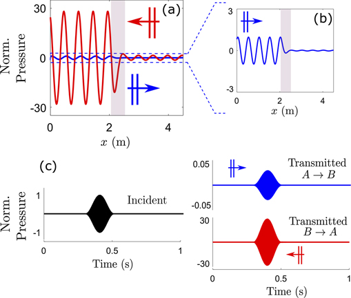
Figure 3. (a) FW simulation of the spatial pressure field for a plane wave incidence from port A (blue) and port B (red) at 692 Hz (frequency shown with black arrow in figure 2(c)) showing 29 dB of amplification for propagation from B to A and 31 dB of attenuation for propagation from A to B. The pressures have been normalized to the maximum incident pressure. A magnified view of the wave propagating from A to B is shown in (b). (c) The time evolution of the wave envelopes of the transmitted pressure at the output of the waveguide due to a 0.2 s cosine squared pulse centered at 692 Hz incident from port A (blue) and port B (red) are shown. The incident pulse is shown (black) for reference. Notice the different pressure scales in the right hand side of panel (c) associated with the different incidence directions. A constant and uniform gain of gd = 4.5 m−1 has been used for each sensor–actuator pair in all simulations.
Download figure:
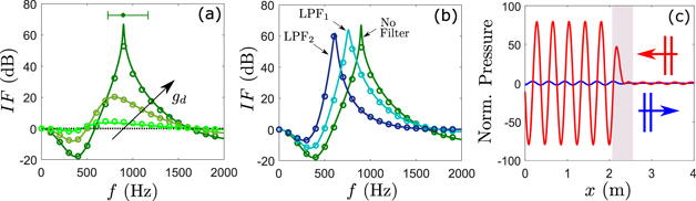
Standard image High-resolution imageTo verify the viability of the spatial feed-forward control with real electromechanical transducers, we relaxed the assumption that the source strength is precisely equal to the sensed pressure, as introduced in (equation (1)). Instead, we used the voltage output from each microphone (sensor) multiplied by a gain factor gd as the input voltage to the corresponding electrodynamic speaker (actuator) to simulate a real experiment. Using standard electrodynamic driver theory [25], we modeled each of the 10 sources with the nominal Thiele-Small parameters for a typical minispeaker, as documented in the supplemental materials. Figure 4(a) shows the IF spectrum for the maximum stable discrete gain,  = 0.086 m−1, 0.04 m−1, 0.01 m−1, and passive waveguide (gd = 0 m−1) to show the change in the IF spectrum with decreasing gain. Reducing gd reduces the peak magnitude and the peak frequency IF. To explore the programmable tunability of the NAM, we added electronic filters in series with the gain gd. Figure 4(b) shows the effect of setting gd = 0.07 m−1 and adding a single pole low-pass filter with corner frequencies of 2000 Hz (LPF1) and 600 Hz (LPF2). The filters introduced a phase shift that resulted in a delay in the signal actuating the speaker, artificially decreasing dff and lowering the peak IF frequency by 140 Hz and 290 Hz for the LPF1 and LPF2 filters, respectively. Figure 4(c) shows FW simulation of the spatial variation of the pressure field at 900 Hz corresponding to unfiltered system. For a 1 Pa (94 dB SPL) incident field, the voltage applied to the speakers remained under the maximum voltage rating for this speaker over the entire range of frequencies. We define ΔfIF as the 20 dB IF bandwidth, and calculated it to be 456 Hz for this system, equal to 51% of the peak IF frequency. Other studies utilizing linear mechanisms to achieve nonreciprocity have reported peak IF magnitudes of around 40 dB (ΔfIF = 4 Hz) for the acoustic circulator [15] and 25 dB (ΔfIF = 250 Hz) for the Willis metamaterial [21]. Hence, this proposed mechanism has the potential to exceed the maximum level and bandwidth achieved by other approaches [15, 21] without disrupting mean fluid flow. Further, the IF spectrum can be manipulated by electronically modulating gd, either in magnitude or in phase (see figures 4(a) and (b)), providing a highly flexible mechanism for in situ optimization of the NAM system for specific applications.
Figure 4. Nonreciprocity in the NAM system with actuators modeled as electrodynamical speakers. (a) The curves show the transition of the IF for increasing gd = 0.01 m−1, 0.04 m−1, and 0.086 m−1 (light to dark shades of green) along with gd = 0 m−1 (black). The lines are calculations from 1D acoustic theory and the symbols are from FW calculations. The 20 dB IF bandwidth is shown as a horizontal line at the top of the plot with the peak IF frequency indicated with a filled circle. (b) Modification of the IF spectra by electronic filters, demonstrating electronic tunability of the system. Addition of a low pass filter in the electronic control moved the frequency of the peak IF by more than half an octave. The gains used were gd = 0.086 m−1 for no filter and gd = 0.07 m−1 for filters with corner frequencies at 2000 Hz (LPF1) and 600 Hz (LPF2). (c) FW simulation of the spatial distribution of the pressure field for a 900 Hz unit amplitude plane wave propagating from B to A (red) and from A to B (blue) when gd = 0.086 m−1. The active section is shown with the shaded box.
Download figure:
Standard image High-resolution image
We have shown that it is possible to induce linear broadband nonreciprocity in acoustic systems, essentially creating a new stable media using the NAM mechanism. This mechanism consists of an array of interlaced subwavelength sensor–actuator unit cells (the total active region can be sub- or supra-wavelength). Although we have demonstrated the approach using a fluid-acoustic medium, this technique can be adopted and applied to many different wave-bearing media and systems. For instance, the locally sensed force or strain in either an interdigitated surface acoustic wave device [30–32] or a layered stack of bulk-wave piezoelectric elements [33, 34] can be fed forward to actuator elements using the NAM approach, creating a preferred direction and nonreciprocity. The NAM approach expands the design space, holding the potential to enhance the desired capability of the device (e.g., filtering or sound output). An extensively studied prototype for wave propagation and control in dispersive systems is an elastic beam bonded to piezoelectric patches arrayed down the beam. When the piezoelectric elements are electrically interconnected by a transmission line, a coupled elastic–electric waveguide is created [35]. While this coupled waveguide system can be designed to achieve excellent stop-band behavior or high losses, it is still reciprocal. By breaking the bidirectionality of the transmission line using the feed forward distributed control of the NAM, these reciprocal systems would be converted to nonreciprocal ones. Another popular approach is to use collocated sensor–actuator patch approaches to control wave propagation on beams, as in [36]. These too can be converted to nonreciprocal systems by feeding forward the control signal to the neighboring patch. Finally, one can also envision creating nonreciprocal anisotropy in two-dimensional media, potentially enabling one-way waveguding. Hence, our theoretical work opens up the possibility of reconfiguring a vast array of well-studied systems rendering them nonreciprocal.
In addition to showing the effectiveness of the NAM concept in breaking reciprocity, we have also highlighted its flexibility in designing systems with desired isolation factor magnitudes and frequencies (figures 4(a) and (b)). This tunability was accomplished with a controller consisting of a spatially constant gain with simple spectral variations. A vast design space associated with the spatio-spectral variation of the amplitude and phase of the gain associated with each sensor–actuator pair as well as the distance between them remains to be explored. Such new designs hold great potential for noise control as well as for enhancement of the performance of electromechanical filters and amplifiers.