


Abstract
High intensity laser-solid interactions can accelerate high energy, low emittance proton beams via the target normal sheath acceleration (TNSA) mechanism. Such beams are useful for a number of applications, including time-resolved proton radiography for basic plasma and high energy density physics studies. In experiments using the OMEGA EP laser system, we perform the first measurements of TNSA proton beams generated by up to 100 ps, kilojoule-class laser pulses with relativistic intensities. By systematically varying the laser pulse duration, we measure degradation of the accelerated proton beam quality as the pulse length increases. Two dimensional particle-in-cell simulations and simple scaling arguments suggest that ion motion during the rise time of the longer pulses leads to extended preformed plasma expansion from the rear target surface and strong filamentary field structures which can deflect ions away from uniform trajectories and therefore lead to large emittance growth.
Export citation and abstract BibTeX RIS
1. Introduction
The interaction of a high intensity laser pulse with thin solid foil targets can produce a burst of high energy ions [1–3] accelerated via the target normal sheath acceleration (TNSA) mechanism [4]. The laser pulse excites a population of hot electrons which stream through the target and establish a strong, electrostatic sheath field on the rear surface. The sheath field can drag protons and other ions out of the contaminant layer on the target surface, accelerating them to energies of many 10s of MeV. The acceleration occurs over time-scales comparable to the laser pulse duration (typically ranging from 100s of fs to 10s of ps). The accelerated beam propagation is nearly laminar [5, 6], emanating from the rear of the target as if from a small, virtual source [7]. These qualities make laser-accelerated ion beams a potentially attractive source for charged particle radiography [7, 8] or fast ignition [9, 10], and could lead to biomedical applications, such as cancer radiotherapy [11], or as a high-current ion injector for conventional accelerators [12] (see also the reviews by Daido et al [13] and Macchi et al [14] and references within).
While improvements to stability, energy, and bandwidth must be made before laser-driven ion beams become a practical source for accelerator or biomedical applications, proton radiography is routinely implemented as a diagnostic tool on high energy, high power laser systems throughout the world. Ultrafast TNSA beams of protons have been instrumental in measuring a number of high energy density (HED) electromagnetic phenomena including laser-driven magnetic field generation [15, 16], Weibel-type filamentation and magnetic self-organization [17, 18], high power laser channeling [19], and laboratory magnetic reconnection [20–22]. Compared to D3He fusion, an alternate HED radiography source which produces mono-energetic protons, the ultrafast proton beams provide improved spatial resolution due to the small virtual source [7, 23] and the quasi-Maxwellian energy spectrum can be employed to achieve temporal resolution by allowing for time-of-flight dispersion of protons before reaching the radiography subject. The broad spectrum makes possible single shot, time-resolved measurements of ultrafast dynamics with picosecond temporal resolution (as shown in [16] and [19]).
In recent years, there has been a concerted computational and experimental effort to revisit the physics of laser-solid interactions on newly available high-energy laser systems. OMEGA EP, for example, is capable of delivering relativistically intense laser pulses (Iλ2 > 1018 Wcm−2 μm2) with kilojoule energies and multipicosecond pulse durations. Simulations suggest that the multipicosecond interaction will heat plasma electrons beyond the ponderomotive potential of the laser [24–27]. Indeed, recent experimental results have confirmed that these high energy, multipicosecond laser systems accelerate ions to maximum energies beyond those predicted by traditionally cited scaling laws [28–30].
While these results are promising, little attention has been paid to the accelerated beam quality. A spatially uniform, low emittance beam is essential for many potential applications of laser-driven protons. In particular, accurate and reproducible diagnosis of electromagnetic fields requires a uniform beam profile. Additionally, attempts to focus or manipulate the beam would be limited by the transverse emittance. Potential gains in maximum proton energy afforded by multipicosecond laser pulses could be outweighed by degraded beam uniformity.
For example, the long rise time of the kilojoule, multipicosecond pulse can preheat the target, initiating plasma expansion from the rear surface [31]. Early work studying the impact of laser prepulse due to amplified spontaneous emission demonstrated that preformed density gradients can suppress the sheath electric field and reduce the maximum accelerated ion energies [32–35]. In addition, expansion of the rear surface can modulate the beam divergence [33, 36] and introduce non-uniform structures into the beam [37].
In this paper we present experiments exploring the impact of laser energy and pulse duration on the accelerated beam quality. The results demonstrate that the proton beam quality is significantly degraded as the laser pulse duration increases. The maximum proton energies agree well with previous results and scalings from kilojoule-class, multipicosecond laser systems, including first published measurements of TNSA driven by 100 ps laser pulses with relativistic intensities. However, the degraded uniformity at longer pulse durations makes these beams unsuitable for proton radiography. 2D particle-in-cell (PIC) simulations suggest that significant plasma expansion and formation of filamentary magnetic field structures during the rise time of the laser pulse increase the emittance of the proton beam for longer pulse durations. These results should inform the development and implementation of proton radiography diagnostics on existing and future HED facilities.
2. Experimental methods
Experiments were performed on the OMEGA EP laser system using two chirped pulse amplified (CPA), infrared (IR) beams. Taking advantage of the flexibility of the OMEGA EP CPA system, laser parameters such as pulse duration and energy were scanned to cover a range of pulse durations (nominally 0.7, 10 and 100 ps). Table 1 lists the laser parameters used in the experiment, including on-shot measurements of the pulse duration [38] and energy. The available laser energy depends on the pulse duration and ranged from approximately 150 to 2000 J. Despite f/1.8 focusing, the focal spot on target is typically large, with 80% of the laser energy contained in a radius, r80 = 15.9 ± 0.8 μm. However, as shown in figure 1(b), on-shot measurements of the laser fluence profile [39] reveal regions with high peak intensity that can be 5–10 times greater the r80 intensity.
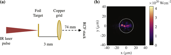
Figure 1. (a) Schematic of the experimental setup. Copper grids were mounted 3 mm behind the 2 mm × 2 mm foil targets. The radiochromic film stack was positioned 74 mm behind the grid. (b) An example vacuum focal plane intensity profile measured on-shot for a pulse with 296 J of energy and a 0.7 ps duration. The white circle encloses 80% of the energy.
Download figure:
Standard image High-resolution imageTable 1. A list of the laser parameters used in the experiment. The nominal pulse duration is shown in the first column. On-shot measurements of pulse duration, laser energy, and focal spot r80 are shown in columns 2, 3, and 4. Calculated laser power (rounded to nearest 5 TW) and peak intensity are in columns 5 and 6.
| Pulse duration | |||||
|---|---|---|---|---|---|
| Nominal (ps) | Measured (ps) | Energy (J) | r80 (μm) | P (TW) | I0 (Wcm−2) |
| 0.7 | 0.7 ± 0.1 | 296 ± 7 | 14.8 | 420 | 4.2 ± 0.4 × 10²⁰ |
| 0.7 | 0.6 ± 0.1 | 143 ± 4 | 17.2 | 240 | 1.8 ± 0.2 × 10²⁰ |
| 10 | 11.5 ± 1.2 | 753 ± 19 | 14.9 | 65 | 5.6 ± 0.6 × 10¹⁹ |
| 10 | 11.1 ± 1.1 | 376 ± 9 | 17.1 | 35 | 1.8 ± 0.2 × 10¹⁹ |
| 100 | 99.7 ± 10.0 | 1944 ± 49 | 15.7 | 20 | 1.5 ± 0.2 × 10¹⁹ |
| 100 | 95.4 ± 9.5 | 1006 ± 25 | 15.4 | 10 | 9.4 ± 1.0 × 10¹⁸ |
The targets were 2 mm × 2 mm flat copper foils with a thickness of 50 μm, and were shot at normal incidence. In order to assess the beam quality of the accelerated protons, a fine copper grid was placed 3 mm behind the foil target. The grid bars were nominally 25 ± 5 μm thick and the width and grid pitch were 10 μm and 83 μm, respectively. Any non-uniformity in the proton beam would be visually represented by a distortion of the imprinted grid pattern.
The accelerated proton beams were detected with layered stacks of radiochromic film (RCF). Exploiting the Bragg peak in proton stopping range, the film stacks were assembled with interleaved layers of film and aluminum filters to sample particular proton energies across the broad energy spectrum. This spectral information is often converted to time-of-flight between the source and the interaction being probed in order to achieve time-resolved radiography. In this experiment, the successive film layers allowed for direct comparison of the beam quality at different proton energies.
The RCF stacks were composed of GafchromicTM HD-V2 and MD-V3 film. After exposure, the pieces of film were digitized with an Epson V850 Pro flatbed scanner with 600 dpi resolution. The raw RCF signal was first converted to optical density (OD = −log10 (Exposed Signal/Unexposed Signal)) and then to deposited dose [40, 41] in order to retrieve the proton fluence.
3. Experimental results
In successive shots, the laser power was scanned between approximately 10 and 420 TW. The detected proton beams are shown in figure 2 grouped by laser pulse duration. As expected, the maximum observed proton energy increased with laser intensity, exceeding 60 MeV from a 0.7 ps pulse with 296 J of laser energy. The longer pulse duration, higher energy shots resulted in more signal at lower proton energies.

Figure 2. Radiochromic film stacks provide a visual comparison of the accelerated proton beam spectra and qualities. The diffuse signal present on later pieces of film, particularly in the nominally 100 ps shots, can likely be attributed to high energy electrons that co-propagate with the proton beam. (It should be noted that a different stack design was used for the 100 ps shots, but comparable penetration depths are shown here.) The color scale saturates low energy portions of the beams to emphasize the comparison between higher proton energies.
Download figure:
Standard image High-resolution imageThe proton spectra were reconstructed following methods outlined in Schollmeier et al [42]. Proton spectra from the highest intensity shots at each pulse duration are shown in figure 3. Taking into account that RCF ion spectrometry is less sensitive than other techniques, such as Thomson Parabola spectroscopy used in [28] and [29], these measurements likely underestimate the cutoff proton energy. Batch-to-batch variations in the sensitivity of the film give rise to a 20%–30% absolute error in determining proton number [43]. The error bars in figure 3 correspond to this absolute error, rather than the relative error between RCF layers.
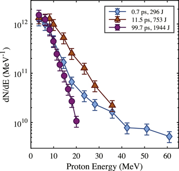
Figure 3. Reconstructed proton spectra from the highest intensity shots for each laser pulse duration.
Download figure:
Standard image High-resolution imageWhile protons were accelerated to energies exceeding 20 MeV with the 1944 J, 99.7 ps pulse, the conversion efficiency was considerably lower than the shorter pulse durations. We estimate a 0.46% ± 0.1% conversion to protons with kinetic energies exceeding 3.5 MeV, compared to 4.7% ± 1% and 3.4% ± 0.9% conversion for the 296 J, 0.7 ps pulse and 753 J, 11.5 ps pulse, respectively. The 11.5 ps pulse resulted in the highest overall beam charge, 2.3 ± 0.5 μC, while the 0.7 ps pulse gave 1.4 ± 0.3 μC and the 99.7 ps pulse gave 1.3 ± 0.5 μC. Note that the low energy portions of the beams overfilled the RCF detectors, and the grid target partially obscured the beams. Therefore, these estimates provide a lower bound on the conversion efficiency and beam charge.
Figures 4(a)–(c) compares representative proton beam profiles for the three pulse durations explored. For clarity, the nominal pulse duration will be used for reference throughout the following discussion. It is immediately evident that the grid pattern is significantly distorted in the 10 ps pulse duration case and completely absent in the 100 ps case. Beyond visual inspection, the 2D Fourier transform of the grid pattern was used to quantify the beam quality across the entire proton energy range for each pulse duration. In Fourier space, a high resolution image of the grid will result in well defined mode structure. As the resolution is degraded, fewer high order modes will be present in the Fourier transform. In addition, distortion or warping of the grid pattern will result in broadening of the mode features. Line-outs through the 2D Fourier transforms of the shown proton data are plotted together in figure 4(d). The periodic mode structure is evident the 0.7 ps data, while the 10 ps results are broadened and less prominent due to the distortion of the grid. Just as there is no visible grid pattern in the 100 ps data, no mode structure appears in the Fourier transform.
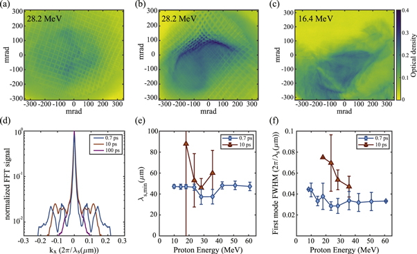
Figure 4. (a)–(c) Selected RCF data from the highest intensity shot for each pulse duration: (a) 0.7 ps, (b) 10 ps, and (c) 100 ps. (d) Line-outs through the 2D Fourier transforms of the data in (a)–(c) shows the effect of the proton beam quality the on mode structure. Analysis of the Fourier transforms reveals the minimum spatial wavelength resolved (e) and the broadening of the first mode peak due to distortion of the grid pattern (f).
Download figure:
Standard image High-resolution imageThe highest order mode observed along the primary grid axes can be interpreted as the average minimum spatial scale resolved (ks,max = 2π/λs,min). Figure 4(e) shows the minimum spatial scale resolved across the entire energy spectrum for the 0.7 and 10 ps results. The error bars include effects of anisotropy in the mode structure (i.e.  ) and uncertainty in the magnification of the grid image. Low energy portions of the beams and all of the 100 ps results fall well above the plotted range. As a measure of the warping and distortion, the full width at half maximum of the first order mode is plotted in figure 4(f).
Overall, the 0.7 ps pulse duration results in the best beam quality. However, even the best beam exhibits degraded imaging quality for protons with kinetic energies below 10 MeV. At higher energies, despite a visually uniform beam and grid structure, the resolution appears degraded likely due to a combination of reduced proton signal, increased transmission through the grids (reduced contrast), and scattering of the high energy protons as they pass through front layers of the RCF stack.
As the laser pulse duration is increased, the beam quality is significantly degraded. Though still visible in the 10 ps case, strong modulations in the beam profile distort and blur the grid pattern. With a 100 ps pulse duration, poor beam quality renders the grid nearly indistinguishable across the entire spectrum.
Even for the most uniform beams, there is still some warping and distortion of the grid pattern. This can likely be attributed to electrical charging of the grid target by the fast electrons passing through in advance of the proton beam and the electrons that co-propagate with the protons. This effect will be more pronounced for slower protons which pass through the grid after charge has been deposited by the higher energy portion of the beam. In addition, the slower velocity means the low energy protons will experience larger deflections. Often times during proton radiography experiments carried out on OMEGA EP, the proton source foil is enclosed in a plastic tube capped by a thin foil in order to protect it from ambient plasma, debris or radiation from the primary interaction (see for example the experimental setup used by Gao et al [15]). This tube assembly could potentially experience similar, or more pronounced, charging effects, impacting the slower portions of the proton beams.
4. Simulation results
In order to explore the impact of laser pulse duration on the underlying interaction dynamics and ion acceleration, we performed 2D PIC simulations with the fully relativistic OSIRIS 4.0 framework [44]. We examined the interaction of laser pulses different durations with over-dense targets. In the experiment, the pulse durations ranged from a few times the ion response time, ti ≈ 2π/ωpi, to 10s or 100s of ti. This suggests that ion motion during the longer pulses likely influences the interaction dynamics and could contribute to differences observed experimentally. Due to the computational expense of carrying out PIC simulations lasting many tens of ps, we chose to reduce the simulated ion mass in order to speed up the ion dynamics. This allows us to approximate the long timescale dynamics with shorter, more computationally accessible pulse durations. The following results compare the interactions of a 1τ0 laser pulse and a 10τ0 pulse, where τ0 is defined to be 100 fs. Consistent with the experiment, the longer pulse duration has more energy, but lower intensity. Here the 1τ0 pulse has a peak normalized intensity (a0) of 5, while the longer 10τ0 pulse is reduced to a0 = 2.5. The laser pulses interact at normal incidence with an over-dense plasma slab. The peak density is 25nc, where  is the critical density for a laser frequency ω0. A uniform exponential profile with a characteristic scale length of λ0/2 extends from the front surface, where λ0 is the laser wavelength. The front and rear surfaces of the target are composed of reduced-mass protons (
 ), while the bulk target has a mass of
  . The bulk target is 10λ0 thick and the rear reduced-mass proton layer thickness is 1λ0. The simulation box size is 1200 × 1200 (c/ω0)2 and is resolved by 12 000 × 12 000 cells with 100 particles-per-cell for both ions and electrons. Cubic particle interpolation was used to limit numerical heating. Absorbing boundary conditions were used for the particles and open, Perfectly Matched Layers (PML) boundaries for the fields.
Previous studies of laser-accelerated proton beams have concluded that filamentation instabilities driven by the high energy electrons determine the beam quality and emittance [6]. The filamented electron beam can drive strong return currents and generate filamentary magnetic field structures which deflect protons away from otherwise uniform trajectories. In addition, the presence of a low density preformed plasma on the rear surface of the target in advance of the peak of the laser pulse has been shown to enhance Weibel-like instability formation that can lead to strong modulations in the accelerated proton beam [45, 46]. Even without filamentation, recent work by Nakatsutsumi et al using higher intensities and thinner targets demonstrated that strong azimuthal magnetic fields on the rear surface can inhibit proton acceleration and impact the beam quality [47]. With these simulations, we investigate the influence of pulse duration on emittance growth mechanisms.
The temporal evolution of the ion density and rear-surface magnetic field are shown in figure 5. In each panel, the time axis is normalized to the rise time of the respective laser pulse, with the peak arriving on target at time = 1. The first column corresponds to the 1τ0 pulse duration and the second column to the 10τ0 pulse duration. The ion density evolution (figures 5(a) and (b)) reveals significantly more expansion of low density plasma from the rear surface of the target during the rise time of the 10τ0 pulse. While filamentary structures are evident in the out-of-plane magnetic field in both pulse duration cases (figures 5(c) and (d)), the fields are enhanced in the longer pulse duration case despite lower incident laser intensity.
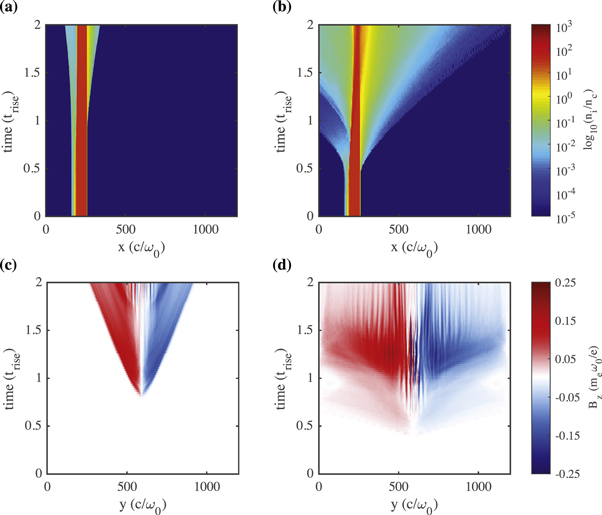
Figure 5. The time evolution of the ion density (a)–(b) and out-of-plane magnetic field (c)–(d) is compared between the two pulse durations. The time axis is normalized to the rise time of the respective laser pulse, with the left column corresponding the a 1τ0 pulse and the right to the 10τ0 pulse. The ion density is measured along the laser axis and the magnetic field is measured at the rear surface of the target.
Download figure:
Standard image High-resolution imageTo assess the accelerated beam quality, the normalized transverse emittance of the protons was measured for 10 bins across the energy spectra. The normalized emittance describes the phase space area occupied by the beam, and is a conserved quantity during vacuum propagation. For the following analysis, the normalized emittance is calculated as:
where y is the transverse spatial dimension, py is the transverse momentum, and  signifies the distribution average. Good beam quality is associated with a lower emittance. Figure 6 shows the temporal evolution of the normalized emittance for both pulse durations as a function of proton energy. Figure 6(a) corresponds the arrival time of the peak of the respective pulse. Panels (b) and (c) correspond to 5τ0 and 10τ0 after the peak, respectively. There is good qualitative agreement between the simulation results and the experiment. The higher energy portions of the short pulse case have the lowest emittance, while the lower energy protons are more strongly impacted by the developing filamentary field structures. The longer pulse duration exhibits a larger overall emittance. In addition, ion acceleration and emittance growth has already commenced by the time the peak of the pulse arrives on target (figure 6(a)).

Figure 6. The normalized emittance, σN, is measured for 10 energy bins across the spectra for both pulse durations. To capture the evolution, the emittance is measured at peak of the pulse (a), 5τ0 after the peak (b), and 10τ0 after the peak (c).
Download figure:
Standard image High-resolution imageDirect comparison of simulations to the experiments is challenging because the interaction and ion acceleration depend strongly the exact details of the laser pulse profile and the target composition and thickness. For example, as previous studies have noted [6], electron-ion collisions in the bulk target will help smooth current filaments, particularly for high-Z target materials. Without including collisions, our simulations potentially overestimate strength of the filaments and the extent of the preformed plasma expansion. However, we do not expect collisional effects to change the general trends observed here.
5. Discussion
In the experiment, we observed a significant degradation of the proton beam quality as we increased the laser pulse duration. The 2D PIC simulation results suggest that ion motion during the rise time of the longer pulses leads to enhanced plasma expansion from the rear surface of the target and to formation of stronger filamentary field structures. The characteristic scale length of preformed plasma at the peak of the pulse can be estimated by  , where
  is the sound speed with hot electron temperature
  , and tp is the pulse duration. The hot electron temperature is given by the ponderomotive potential [48] of the half-maximum laser intensity,
 ![${k}_{B}{T}_{{he}}={m}_{e}{c}^{2}[{\left(1+\langle {a}_{0}/2{\rangle }^{2}\right)}^{1/2}-1]$](https://content.cld.iop.org/journals/1367-2630/21/10/103021/revision2/njpab4721ieqn9.gif) , (here,
, (here,  represents the time average). From this, we can derive an approximate scaling for the characteristic plasma gradient length as a function of pulse duration and peak intensity,

Figure 7 shows a comparison of this simple model and the density profiles observed in the simulation. While the model overestimates the plasma scale length for the shorter pulse duration, there is reasonable agreement for the longer pulse duration case. At the very least, the model provides order of magnitude estimates of the extent of plasma formation on the rear surface. Turning to the experimental data, we predict ls ≈ 6, 50, and 266 μm for the 0.7, 10, and 100 ps pulse duration shots compared in figures 3 and 4. While charging of the secondary target certainly contributes to the distortion of the grid pattern, simulations suggests that most of the structures and non-uniformity in the beam can be attributed to pre-expansion of the target.

Figure 7. At the peak of the respective laser pulse, the rear surface plasma profile from the simulations is compared with the simple scale length estimate developed in the text (dashed lines).
Download figure:
Standard image High-resolution imageIn addition to degrading the beam quality, large preformed plasma density gradients should reduce maximum proton energies. With a sharp interface, the maximum sheath electric field is given  , where
  is the hot electron temperature, e is the electron charge, and λD is the Debye length [49]. However if ls ≫ λD, the field is reduced to
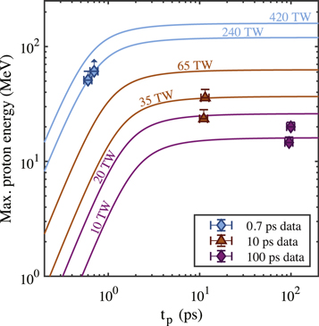
  [34]. Alternatively, strong magnetic fields can inhibit sheath formation by confining or scattering hot electrons away from the central axis [47]. In figure 8, the maximum proton energies observed in the experiment are compared with predictions based on the analytical model described by Schreiber et al [50]. As mentioned above, the RCF measurements likely slightly underestimate the maximum proton energies and represent a lower bound. In general, the 0.7 ps results show reasonable agreement with the model, while the 10 and 100 ps results fall below the predictions. Unlike other models [49, 51], the Schreiber model stays finite as
  , and therefore appears to more accurately predict the maximum proton energies for the 100 ps pulse duration results. Despite the long scale lengths predicted, protons are still accelerated to multi-MeV energies in all cases, potentially due to the impact of super-ponderomotive electron heating or laser self-focusing in front-side preformed plasma. Maximum energies measured here in the 100 ps pulse duration case exceed previous observations from kilojoule-class laser-solid interactions with 100s of ps pulse durations and lower intensities [52, 53].
Figure 8. The maximum proton energies observed in the experiment are compared to the analytical model developed by Schreiber et al [50]. For the highest intensity shot with a 0.7 ps pulse duration, the arrow indicates that the proton energy spectrum extended beyond the range detected by the RCF stack by an unknown amount.
Download figure:
Standard image High-resolution image
6. Conclusion
For high energy, high power laser systems, these results demonstrate that the laser pulse duration should be minimized to limit pre-expansion of plasma from the rear target surface and ensure optimal proton beam quality. While the promise of superponderomotive electron heating and favorable ion energy scaling from multipicosecond interactions may yet prove useful for other applications, such as fast ignition [9, 10] and neutron generation [54, 55], the non-uniformity of the accelerated proton beams make them unsuitable for ultrafast proton radiography or other applications that require a uniform, low-emittance beam. Even with optimal laser pulse conditions, proton radiography experiments and detector stacks should be designed to emphasize protons with energies exceeding 10 MeV. These results can help guide future experimental designs both on OMEGA EP and other HED facilities, such as the NIF-ARC which can also produce kilojoule, multipicosecond laser pulses.
Acknowledgments
The authors would like to acknowledge the OMEGA EP staff at the Laboratory for Laser Energetics, Sarah Mueller of General Atomics for assembling the targets, Charlotte Palmer of University of Oxford and David Carroll of the Rutherford Appleton Laboratory for helpful communication regarding radiochromic film and Michael Pillainayagam and Dr Dale Litzenberg of the Radiation Oncology department of Michigan Medicine for their assistance calibrating radiochromic film. The authors would also like to acknowledge the OSIRIS Consortium, consisting of UCLA and IST (Lisbon, Portugal) for providing access to the OSIRIS 4.0 framework. Work supported by NSF ACI-1339893.
This material is based upon work supported by the Department of Energy/NNSA under Award Numbers DE-NA0002372 and DE-NA0002727.