


Abstract
Modern high performance circular accelerators require sophisticated corrections of nonlinear lattices. The beam betatron tune footprint may cross many resonances, reducing dynamic aperture and causing particle loss. However, if particles cross a resonance reasonably fast, the beam deterioration may be minimized. This paper describes the experiments with the beam passing through a half-integer resonance stopband via tune modulation by exciting synchrotron oscillations. This is the first time that beam dynamics have been kept under precise control while the beam crosses a half-integer resonance. Our results convincingly demonstrate that particles can cross the half-integer resonance without being lost if the passage is reasonably fast and the resonance stopband is sufficiently narrow.
Export citation and abstract BibTeX RIS
1. Introduction
It has become standard practice to constrain the particle's tune footprint while designing the storage ring lattice so that the particle tunes fit between harmful resonances, which limit ring dynamic aperture (DA) [1]. This approach, known as 'tune confinement', puts tight limits on the magnitude of the tune shifts with amplitude and with momentum. The latter requires labor-intensive optimization of the off-momentum DA and the corresponding tune footprint for the large momentum deviations to achieve a reasonable lifetime.
As nonlinearities of the modern ring lattices are much enhanced as compared with the previous generation of synchrotrons, it is becoming more and more difficult to keep the off-momentum tune footprint inside the range surrounded by the resonance lines [2–4]. One of the major resonances is the half-integer resonance and it is always treated as an unstable working point that may cause beam loss. The half-integer resonance poses concerns in many circular accelerators, such as modern synchrotron light sources [2, 3], heavy ion medical accelerators [5] and non-scaling fixed-field alternating-gradient (FFAG) accelerators [6].
Intuitively, if the particle crosses the stopband quickly, one may expect that the betatron oscillation amplitude will not increase substantially thereby keeping the particle within the machine acceptance. At the same time, the tight tolerances with which modern lattice elements can be designed and produced afford much narrower resonance stopbands when compared with machines built decades ago.
Recently modern synchrotrons advanced to multi-bend achromat lattices featuring small dispersion and low beta functions, and high nonlinearity of the particle motion due to stronger sextupoles. In certain cases [2, 3], the tune spread for on-energy beam was successfully minimized, but the off-momentum tunes swing across the major resonances, as shown in figure 1. However, the tracking result did not show particle losses in contrast to the experiments [5, 7] on resonance crossing where the beam losses were observed.

Download figure:
Standard image High-resolution imageIn this paper we investigate, both analytically and experimentally, the beam dynamics during crossing of a major resonance in one of the lowest-emittance storage rings worldwide. This is the first time in storage ring experiments that the beam crossed the half-integer resonance without losses due to the fast passage and narrow resonance stopband width.
The authors of [2] found during tracking studies with the APS-U lattices that the half-integer resonance is transparent for particle motion. They explained this phenomenon as resulting from the rapid transition of the particle through the stopband together with substantial amplitude-dependent tune shifts which helped move the tune off the resonance during the transition. The results of our studies presented in this paper indicate that this explanation is adequate.
The topic of resonance crossing and rapid tune manipulations in circular accelerators has been studied in the past. In the 1970s Chasman et al [8], Evens and Gareyte [9] and Bruck [10] analyzed the repetitive crossing of an isolated resonance driven by a single multipole term. In [11] the authors solved the problem of multiple crossing of a nonlinear resonance by tune modulation and the overall emittance growth with the assumption that the phase of betatron oscillation is uncorrelated between successive crossings. Chao and Month [12] obtained expressions for efficiency of particle trapping while the bunch traverses an isolated nonlinear resonance and demonstrated that the trapping efficiency depends on the resonance width, the speed of traversing the resonance and the nonlinear detuning. Additionally, in 1970 Pellegrini and Sessler developed a formalism for calculating the displacement and width of a bunch of particles passing through an integer resonance by additional focusing (and the corresponding tune shift) produced by the ions trapped in the storage ring [13]. The authors calculated betatron amplitude growth rates [14, 15] and presented the emittance growth factor [16–18] for particles traversing different resonances. Lysenko [15] analyzed betatron amplitude growth in the cases when the particle tune is fixed, moves along a single resonance line or crosses an isolated resonance. Later, in 1991, Mane and Weng studied the cases of single and repetitive resonance crossing caused by power supply noise or by synchrotron oscillations, including consideration of amplitude-dependent tune shift and growth of emittance [19]. Experimental results on passing a half-integer resonance in the Heavy Ion Medical Accelerator by means of a fast modulation of a quadrupole were presented [5]. Beam loss was observed. Experimental results of the crossing of a nonlinear third-order resonance at an electron–positron collider were presented in [20]. Other experimenters [21] have measured exponential gain in the ratio of betatron amplitudes before and after crossing 3/2 resonance in a cyclotron as a function of the resonant harmonic amplitude in the magnetic field index around the ring. The experiments on integer resonance crossing in EMMA, a non-scaling FFAG constructed at Daresbury Laboratory in the UK, were described in a detailed PhD thesis [22].
This paper is organized as follows:
- Section 2 discusses beam dynamics of the particle crossing a static resonance stopband. We also describe our method to control the tune swing by choosing a large chromatic tune shift in the vertical plane and driving large synchrotron oscillation.
- Section 3 discusses the ways to control the resonance stopband width and the measurement results for half-integer resonance characterization at Brookhaven National Laboratory's NSLS-II facility.
- Section 4 provides an analytical solution of beam parametric oscillations in close proximity to the half-integer resonance and beam oscillation amplitude amplification factor while crossing half-integer.
- Section 5 describes the concept of the experiment.
- Section 6 presents the measurement results.
- Section 7 concludes with our findings.
2. Dynamics of the particle crossing a static resonance stopband
We consider a storage ring model with large chromatic tune shift and a particle with momentum deviation  up to the second order writing the particle's tune shift as:

where ξ1 and ξ2 are linear and 2nd order chromaticities. In the following, we constrain our analysis to the two-dimensional case of y and δ. For our experiments we kept ξ1y = +1 and tuned the 2nd order chromaticity to ξ2y = +300 (the same value as in [2, 3]) by changing ring sextupoles while maintaining small tune shifts with amplitude.
Next we assume that the particle energy oscillates with the maximum deviation δ0 and this synchrotron oscillation, for simplicity, is taken as  where
where  is the synchrotron tune and n is the number of turns around the ring. An illustration of the problem under consideration is shown in the left plot of figure 2. As can be seen, the betatron tune of a longitudinally oscillating particle crosses the half integer resonance νR = p/2, which has a stopband width that depends on quadrupole errors. The resonance is characterized by a stopband with the width
  which is heuristically defined as the boundary of the tune range where the peak beta-beat
  reaches 100% [23]. Here p is an integer number,
  is the reference beta function calculated from the unperturbed lattice model, and
  is the measured beta function obtained from beam oscillations excited by a pulsed kicker and measured by beam position monitors (BPMs) distributed around the ring [24].

Figure 2. Left-hand plot: particle's synchrotron oscillations with maximum amplitude δ0 crossing resonance at νR = p/2 with the stopband width of  and lower scale refers to the momentum deviation versus RF phase φ(t). Right-hand plot: measurement of the ½ resonance stopband width
  at NSLS-II using the scan of quadrupole gradients
  (blue points), the scan of RF frequency ΔfRF (red points) and their fits.
Download figure:
Standard image High-resolution imageThe right-hand plot of figure 2 shows the resonance stopband measured at NSLS-II using two techniques to control the tune: a scan of the quadrupole gradients and a scan of the RF frequency. Applying the first technique we adjusted the quadrupole gradients  to move the tune around the resonance and measure beta-beat as a function of the tune. We measured the second curve by moving the tune via changing the momentum deviation according to (1). We accomplished the latter by changing the RF frequency and scanning the tune through the resonance similar to changing ring quadrupole strengths
We define δR = δ(νR) as the value of the energy deviation where the particle's tune crosses the resonance νR. The boundaries of energy deviation that correspond to the resonance stopband  are (neglecting the contribution from the linear chromaticity ξ1 and assuming that
  and
and  is positive):
For calculating the number of turns the particle takes to cross the stopband we get:
Due to the radiation damping the amplitude of energy oscillations δ will decay below δR after the time interval ΔT = NcrossTs/2, where Ts is the synchrotron period,  corresponds to the number of crossings of the resonance stopband when
  and τs is the damping time. This expression is an approximate result since we are not taking quantum excitation into account.
Note that we made the two following assumptions in this section: first, we assumed that the detuning effect from betatron oscillations is insignificant as compared with the detuning from energy oscillations. This holds only for small amplitudes of betatron motion and, thus, we limited the range of amplitudes in our experiments to within a few millimeters. Second, we assumed that the resonance stopband is 'static', i.e. it does not change with the energy deviation δ. The latter means that the chromatic widening of the resonance stopband is smaller than that driven by errors in quadrupole gradients.
As shown in the right-hand plot of figure 2, the measured stopband does not change significantly between the quadrupole scan and the RF frequency scan, which supports our second assumption.
3. Controlling the resonance stopband width
Quadrupole imperfections of the linear lattice lead to a betatron tune shift as well as forming a finite bandwidth of resonances on the tune diagram. The tune shift and half-integer stopband width are determined correspondingly by the 0th and pth harmonics of quadrupole perturbations around the machine (we are using largely the same notation as in [23]):

where p is close to  , q runs over the lattice quadrupoles,
  and
and  are betatron amplitude and phase and
  is the perturbed quadrupole focusing strength.
The way to control the resonance stopband width  is to act on the pth harmonic of
  while maintaining the 0th harmonic caused by the same
  equal to zero. Methods of minimizing the stopband width were presented in [25].
In the experiments we characterized the resonance stopband using the two ways of tune scans described above, resulting in the measured  of 0.016 with accuracy of about ±0.0025. We assume the beta-beat distribution along the ring as the sum of harmonic functions and calculate the rms beta-beat driven by random Gaussian distributed errors in the ring quadrupole settings as:
where Mq is the total number of quadrupoles. Using the measured value of beta-beat (3%) we calculate the rms perturbations in Mq = 300 NSLS-II quadrupoles as  = 0.13%. From these perturbations we estimate the ½ resonance stopband width
  via (3) as 0.015, which closely corresponds to our measurements reported in figure 2.
To control the stopband width, defined in (3), we selected several quadrupoles separated by n · π + π/2 in betatron phase advance  and changed their strength by
  yielding the maximum change in the stopband width of
4. Parametric oscillator excited at ½ resonance
We solved the perturbed Hill's equation with normalized variables via the Floquet transformation.
where  is the betatron tune,
  is an integer number,
  ≪
≪  is static detuning from the half-integer resonance,
  β is beta-function,
  is the phase, which changes by 2π every turn and Δk1(s) is a perturbation of quadrupole k1(s).
Following [1] we expand the RHS of the equation above in Fourier series and retain only the resonance harmonic of the perturbation arriving to the Mathieu equation:

where  is the stopband width as in (3). We carry out the method of slowly varying amplitudes and obtain the solution [26]:
where 

 and
and  are defined by the initial conditions of
  and
and 
 phase are defined as
  and
and 
When the tune is out of stopband, i.e.  particle motion is stable. When the tune is within the stopband with
  the amplitude of motion increases exponentially. The oscillation amplitude
  is given by
  since the second term in (5) becomes insignificant after a few turns.
In our experiment the detuning,  =
=  =
=  is not constant but changes every turn. We note that the corresponding change in ν is slow as compared with the value of the tune itself:
  so
so  varies slowly and crossing the stopband takes a large number of betatron oscillations.
To assess the increase of betatron amplitude  during the resonance crossing we solved the equation (4) numerically. Results of this solution are presented as the red trace in figure 3 and compared with particle tracking results using code Elegant [27] for the conditions of our experiment at NSLS-II.

Figure 3. Betatron oscillations versus turn number. The red curve corresponds to numerical solution of equation (4) and the blue curve shows a result of particle tracking using code Elegant (oscillation of the beam centroid, with the envelope determined by rms beam size to evaluate the decoherence effect). The green trace shows tune evolution with dashed lines indicating borders of the stopband.
Download figure:
Standard image High-resolution imageThe turn-by-turn (TBT) graphs of the beam centroid position and its rms size obtained from multi-particle tracking simulations are shown as the blue trace in figure 3. The beam transverse oscillation is excited at the 20th turn by a pulsed kicker. The tune manipulation, according to equation (1), is accomplished by the excitation of synchrotron oscillations using fast shift of the RF phase (also referred to as RF phase jump) at the 120th turn. The tune crosses the half-integer resonance twice: the first crossing occurs around the 140th turn, where one can see the oscillation amplitude ramping up; and the second crossing is at around the 175th turn. The oscillation decoherence becomes significant at large beam oscillation amplitudes.
As follows from figure 3, the oscillatory solution is modulated with the beat frequency μ in proximity to the stopband to a rapid growth of the oscillation envelope while the tune approaches the stopband and crosses it. The nature of the increase in the amplitude fits with the model described by equation (4) adequately and shows good agreement with the output of the Elegant. We note that these solutions deviate at the top of the first maximum of the oscillation envelope because of the tune shift with amplitude, which is not taken into account in (4) and filamentation of the particle distribution due to high chromaticity.
To estimate the increase of amplitude after a single passage of the stopband, we developed a simplified solution of equation (4). The ratio of betatron oscillation amplitudes before (i) and after (f) passing the resonance is as follows:

with  estimated using the first expression of (2), as the number of ring revolutions while the particle is moving through the resonance stopband. When the particle moves through the unstable region, the growth rate varies from zero (when
  to a maximum (when
  ), and then back down to zero again (when
  ). In order to obtain a bound on the amplitude overall growth, we assume that the instantaneous growth rate equals the maximum growth rate, i.e.
  when the particle motion resides in the unstable region. This method then gives the solution of growth rate as equation (6).
We applied the expression above to the case depicted in figure 3 and obtained the gain in amplitude as a result of a single passage through the resonance as approximately 2 for the stopband width as mentioned in section 3, which is in reasonable agreement with the numerical results plotted in figure 3.
We note that a similar estimate of the amplitude gain factor was reported in [28], whereas the analytic solution of slow passage through a resonance governed by the Mathieu equation was presented in [29].
5. Concept of the experiment
We carried out our experimental studies at the NSLS-II storage ring. The NSLS-II is a high-brightness synchrotron light source based upon a 3 GeV storage ring with a 30-cell double-bend-achromat lattice complimented by damping wigglers in order to reduce the emittance below 1 nm rad [30]. In table 1 we present the beam parameters of the NSLS-II storage ring relevant to our experiments.
Table 1. NSLS-II storage ring beam parameters.
| Vertical betatron tune | 16.26...16.55 |
| Revolution period, μs | 2.64 |
| Synchrotron tune | 0.006 25 |
| Damping time (x/y/z), ms | 55.3/55.3/27.7 |
| Vertical emittance, pm rad | 30 |
| Energy spread, % | 0.05 |
In our experiments we moved the tune  to a proximity of a half integer resonance located at 16.5 and excited the beam vertical betatron oscillations with a transverse pulsed kicker. TBT beam transverse positions and beam relative intensity were measured with BPMs. The vertical TBT data showed modulated betatron oscillations, which provided a convenient tool for independent measurement of the detuning
  and
and  using the solution of equation (5). Rapid changes of the RF phase at some delay with respect to the transverse kicker pulse induced beam energy oscillation large enough to cross the resonance stopband.
Beam TBT energy oscillation was retrieved from the horizontal data of the BPMs located in the dispersion region. Also we measured the first and second order dispersion and chromaticity by scanning the RF frequency, which provided the necessary calibration of the energy and tune oscillations [31].
While the beam crosses the resonance its motion is affected by rapid decoherence of the betatron oscillations. The small transverse size and energy spread of the bunch prior to the transition allowed us to observe coherent betatron motion as the bunch was crossing the resonance stopband. In our experiments at NSLS-II the transverse and longitudinal pinger amplitudes (Δα = 200 μrad and δ0 = 1.5%) exceeded the natural beam divergence (1.5 μrad) and the energy spread (0.05%) by the ratio of about a hundred. Therefore the decoherence of beam oscillation and subsequent filamentation of the particle distribution become significant only after the beam has crossed the resonance, thus not masking the BPM TBT signals of the coherent particle motion during the transition.
In order to modulate the off-energy tune in this experiment, we developed a method of rapid excitation of coherent beam energy oscillations ('RF jump' or 'RF pinger', [31]). The NSLS-II Low Level RF controller [32] was modified by adding an external timing trigger to control the phase transient.
The RF pinger timing was aligned with other timing-driven subsystems, such as transverse kicker and BPMs as shown in figure 4. The timing delay for the RF pinger trigger was synchronized with and delayed by 100 turns relative to the transverse kicker in order to monitor beam betatron oscillation and energy oscillation.
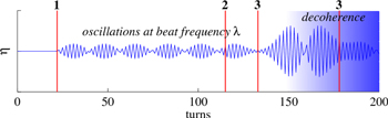
Figure 4. Timing diagram. The numerical solution of equation (4) is presented by the blue line, the major events are indicated by the vertical red lines: 1—transverse kicker, 2—RF pinger, 3—resonance crossings.
Download figure:
Standard image High-resolution imageRF feedback gain parameters were also optimized so that the RF phase transition excited the beam synchrotron oscillations with the maximum amplitude [31, 32].
6. Experimental results
In the experiment, we stored a beam current of a few milliamperes, switched to the lattice with high ξ2 and then moved the betatron tune to a near half-integer resonance (ν0 ∼ 16.47) by controlling non-dispersive quadrupoles.
The beta-beat along the ring at different tunes was retrieved from BPM TBT data to measure the stopband width. The beta beat for the nominal lattice was corrected to ∼3% with stopband width at 0.016. We called these experimental conditions the 'small stopband' scenario.
With the same RF jump and transverse kicker settings we designed another experimental scenario in which the quadrupole strength was adjusted to expand the stopband width from 0.016 to 0.038, so that the beam tune stays within the stopband much longer during the RF jump. We called these experimental conditions the 'large stopband' scenario.
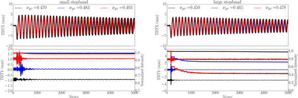
The measurement results are shown in figure 5 including traces of the vertical tune, vertical beam position and beam normalized intensity. Beam energy oscillation amplitude is about +/−1.4% (peak to peak), as retrieved from the horizontal beam position measured by BPMs. The tune modulation is calculated using equation (1) and presented in the upper plots. Different colors correspond to the different values of the initial tune  When the tune approaches the resonance, motion in the vertical plane exhibits the behavior typical for parametric resonance, i.e. modulation at the detuning frequency Δν, which is in the range between 20 and 120 turns for our experimental conditions.
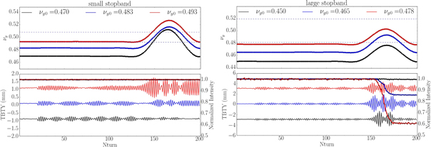
Figure 5. TBT beam parameters (upper plot: calculated y-tunes with dashed lines indicating borders of the stopband, lower plot: BPM measured TBT y-position on left axis and normalized beam intensity on right axis) for the three separate experiments with different initial tunes prior to triggering the RF phase jump. The left-hand plot corresponds to the 'small stopband' case and the right-hand plot corresponds to the 'large stopband' case.
Download figure:
Standard image High-resolution imageIn the left-hand plot of figure 5 we plotted the data with different initial vertical tunes: 0.470 (black), 0.483 (blue), 0.493 (red). With these initial conditions the beam takes approximately 11, 12 and 17 turns to cross the resonance. The difference in the oscillation amplitude after the first crossing is visible but in every case there is no beam loss. In the 'large stopband' scenario, there is no beam loss while the tune is outside of the resonance stopband, but when the beam is moving through the resonance for about 40 turns, particle loss occurs. The losses then repeat during subsequent synchrotron oscillations.
With equation (2) we estimate that the maximum number of turns the beam can spend within the 'small stopband' is about 25 and for the 'large stopband' it is about 49. Using equation (6) we estimate the betatron amplitude growth under our experimental conditions as a factor of 3.5 for the 'small stopband' and a factor of 350 for the 'large stopband'. This large amplification factor for the 'large stopband' leads to significant beam loss as demonstrated by our experiments. Since about half of the beam intensity is lost after the first crossing of the stopband, the plots of vertical TBT data in this case are not representative of the actual beam betatron motion.
We note that we were able to study vertical TBT data corresponding to the first crossing of the resonance during the first half-period of the energy oscillation. Clear exponential-like growth of betatron motion is visible only during the first crossing. During the next few synchrotron oscillations the BPM TBT signal blurs due to the decoherence and filamentation of the beam as the particles are repetitively passing through the stopband.
Figure 6 shows oscillations of the beam position and evolution of the beam intensity over a longer period of time, 5000 turns, which is equivalent to about half of the radiation damping time. The upper plot of figure 6 presents oscillations in the horizontal position as measured by the BPMs at non-zero dispersion location. The shape of the waveform is asymmetric due to contributions from the second order dispersion. We took this effect into account while retrieving beam energy dependence on the turn number from the TBT data [31]. The oscillation envelope decays exponentially due to the radiation damping.
Figure 6. TBT beam parameters (upper plots: horizontal position, lower plots: vertical position on left axis and beam intensity on right axis) for both cases of 'small stopband' (left plot) and 'large stopband' (right plot). The horizontal axis extends to 5000 turns so that 40 synchrotron oscillations are shown.
Download figure:
Standard image High-resolution image
We carried out studies of the beam executing large-amplitude synchrotron oscillations and crossing a major machine resonance in the storage ring with high chromaticity. First we designed a lattice with high second order chromaticity and characterized its properties. Next we developed and tested an experimental technique, 'RF pinger' [31], which provided us with a way to excite synchrotron oscillations of the whole beam at an amplitude sufficient to cross the ½ resonance. We measured the resonance stopband using scans of quadrupole gradients  and energy deviation and developed solutions with two different stopband widths.
In our experiments we studied the beam coherent oscillations during the crossing of the resonance stopband as if the beam was a single particle. Due to the constraints imposed by this experimental method we could not study the dynamics of multiple crossings of the resonance, which may be the subject of our future experiments.
Considerations presented in this paper can be readily applied to the analysis of beam dynamics in the new generation of synchrotrons [2, 3]. For instance, we estimate a gain in the betatron oscillation amplitude of a particle crossing the resonance for conditions similar to [2] or [3], i.e. ξ2 ≈ 300. Using equation (2) we calculate the number of turns that the particle takes to cross the resonance stopband is  turns with an assumption on the stopband width of 0.02 as at NSLS-II and
  as in [2]. The gain factor
  estimated via equation (6) gives 1.2 for the single crossing of the stopband. Due to low synchrotron frequency (taking Ts ≈ 1.4 ms and τs ≈ 14 ms from the APS-U design report) we get the total number of crossings
  and therefore the total gain in the amplitude of betatron oscillation amplitude cannot exceed a factor of 2.
We note that, as predicted [8, 11], in the case of large  the partial increases in the betatron amplitude per crossing should add up 'incoherently', i.e. the growth of amplitude follows the random walk process. This happens because there are a large number of betatron oscillations between successive crossings and particles enter the resonance stopband with the uncorrelated betatron phases from one crossing to the next.
7. Conclusions
In summary, we carried out a study focused on beam dynamics in a storage ring featuring a large chromatic tune footprint that can span across major resonances. Such a property of the ring lattices has been recently identified during the design of the new multi-bend achromat lattices [2, 3] proposed for the next generation of synchrotron light sources.
We have shown that it is possible, both by design and by experiment, to achieve the storage ring conditions where the beam crosses the ½ resonance without particle loss. This can be accomplished if the stopband is narrow due to small residual field errors in the ring magnets and is further controlled by accurate cancellation of the harmful harmonic of the field errors around the ring. The combination of the small stopband width with a large magnitude of nonlinear chromaticity leads to the rapid crossing of the resonance, which does not cause loss of the particles as demonstrated by our experiments.
We studied the motion of particles in the vicinity of a single resonance and could not cross the whole range of tunes covered by the footprint similar to [2, 3]. The amplitude of momentum oscillations that we were able to excite with our RF-pinger technique was limited by the reflected power during transition of the RF cavity phase and was about 1%, while the maximum amplitudes in the cases of [2, 3] reach or exceed 3%. Another limitation of our technique comes from the fast decoherence of the beam oscillations masking coherent beam motion during subsequent crossings of the resonance.
Acknowledgments
We are grateful to F Willeke and S Y Lee for helpful discussions and advice related to this paper. T Shaftan is thankful to N A Vinokurov and E B Levichev for insightful discussions on particle dynamics. We appreciate the leadership and help from the NSLS-II RF group for jointly developing and characterizing a powerful diagnostic tool for the beam longitudinal plane—the RF pinger. This work was supported by the U.S. Department of Energy contract no: DE-SC0012704.