


Abstract
The generation of extreme-ultraviolet (XUV) isolated attosecond pulses (IAPs) has enabled experimental access to the fastest phenomena in nature observed so far, namely the dynamics of electrons in atoms, molecules and solids. However, nowadays the highest repetition rates at which IAPs can be generated lies in the  range. This represents a rather severe restriction for numerous experiments involving the detection of charged particles, where the desired number of generated particles per shot is limited by space charge effects to ideally one. Here, we present a theoretical study on the possibility of efficiently producing IAPs at multi-
 repetition rates via cavity-enhanced high-harmonic generation (HHG). To this end, we assume parameters of state-of-the-art Yb-based femtosecond laser technology to evaluate several time-gating methods which could generate IAPs in enhancement cavities. We identify polarization gating and a new method, employing non-collinear optical gating in a tailored transverse cavity mode, as suitable candidates and analyze these via extensive numerical modeling. The latter, which we dub transverse mode gating (TMG) promises the highest efficiency and robustness. Assuming 0.7
  , 5-cycle pulses from the seeding laser and a state-of-the-art enhancement cavity, we show that TMG bares the potential to generate IAPs with photon energies around
  and a photon flux of at least
  at repetition rates of
  and higher. This result reveals a roadmap towards a dramatic decrease in measurement time (and, equivalently, an increase in the signal-to-noise ratio) in photoelectron spectroscopy and microscopy. In particular, it paves the way to combining attosecond streaking with photoelectron emission microscopy, affording, for the first time, the spatially and temporally resolved observation of plasmonic fields in nanostructures. Furthermore, it promises the generation of frequency combs with an unprecedented bandwidth for XUV precision spectroscopy.
Export citation and abstract BibTeX RIS

Original content from this work may be used under the terms of the Creative Commons Attribution 3.0 licence. Any further distribution of this work must maintain attribution to the author(s) and the title of the work, journal citation and DOI.
1. Introduction
Towards the end of the last century, the duration of pulses produced with modelocked lasers had approached the limits imposed by increasing material dispersion towards the ultraviolet, corresponding to just a few cycles of the carrier wave [1]. The ability to stabilize the carrier-to-envelope phase (CEP) of such pulses and to amplify them to intensities at which their electric fields rival the atomic Coulomb field allowed for the generation of extreme-ultraviolet (XUV) isolated attosecond pulses (IAPs) via the highly nonlinear process of high-harmonic generation (HHG). The first XUV–IAPs were shown in 2001 [2] and enabled experimental access to the hitherto fastest phenomena observable in real time, namely electron dynamics in atoms, molecules, solids and plasmas [1, 3].
Currently, titanium–sapphire-based (Ti:Sa) ultrashort-pulsed lasers represent the workhorse technology for experiments in attosecond physics. However, strong absorption and thermal lensing in the Ti:Sa gain medium [4] limits the generation of high-energy ultrashort pulses to repetition rates significantly lower than  . In particular experiments which involve the detection of charged particles would tremendously profit from IAPs at higher repetition rates: in this class of experiments, space charge effects limit the detection to ideally a single particle per shot, so that the data acquisition rate scales with the repetition rate rather than with the total photon flux. Examples include coincidence spectroscopy [5], time-resolved spectroscopy/microscopy of nano-plasmonic fields [6–8], and of ultrafast electron dynamics in nano-structured topological insulators [9], just to name a few.
Coherently stacking the pulses of a high-repetition-rate modelocked laser inside of a passive optical resonator, or enhancement cavity (EC), provides a convenient way to combine peak intensities on the order of  necessary for HHG in a gas target with pulse repetition rates of several (tens of) MHz [10, 11]. With the advent of Yb-based lasers, ECs have enabled reaching these intensities at the highest repetition rates so far, providing ultrashort pulses with the highest average powers ever demonstrated [12], and allowing for HHG with photon energies exceeding 100 eV at repetition rates as high as 250 MHz [13]. Just a few years ago, femtosecond ECs have been used for the first frequency comb spectroscopy experiments in the vacuum ultraviolet spectral region [14, 15]. Owing to recent progress concerning advanced cavity designs [12, 16], the quantitative understanding of the intracavity gas target nonlinearity [17–19], and thanks to scaling the bandwidth of ECs [20] and of phase-stable, high-power seeding laser systems [21–23], it seems feasible as from today's point of view to extend this technology to application in attosecond physics. However, state-of-the-art dielectric multilayer optics cannot cover the bandwidth necessary for single-cycle near-infrared pulses [20], which would enable the direct generation of IAPs in ECs.
In this paper we theoretically study the possibility of efficiently generating IAPs using ECs supporting pulses comprising several cycles. We identify and, employing thorough modeling, compare suitable time-gating methods and reach the conclusion that the generation of IAPs with sufficient photon flux for multi-MHz-repetition-rate experiments is within reach with current laser technology.
In section 2, we first review the state of the art of ultrashort-pulse ECs, deriving the parameter range for our study, and describe the computational model used for the simulations. In section 3, established gating methods are assessed for compatibility with the geometry, bandwidth and loss restrictions of ECs, allowing us to identify the most promising candidates. For a fair comparison of these candidates, all relevant parameters are optimized for IAPs with highest photon flux in a defined spectral range, within the technical constraints set by state-of-the-art experiments. Finally, in section 4 we compare the results of the optimized gating schemes, identify a preferred one and estimate the achievable photon flux. Section 5 concludes the paper and addresses the implications for time-resolved spectroscopy applications at high repetition rate.
2. Methods
2.1. State of the art of HHG in femtosecond ECs
HHG in ECs has been an active research topic in the last years, and many prerequisites to generate high-repetition-rate IAPs have already been established. First, XUV radiation is emitted collinearly with the strong driving beam, it needs to be separated without introducing too much loss to the driving field. Several approaches have been demonstrated, offering output coupling efficiencies between 5 and around 20% [24]. Most suitable for the generation of IAPs seem geometrical output coupling techniques [25, 26], which are power-scalable and do neither angularly disperse nor spectrally alter the XUV beam because it leaves the resonator without reflection or diffraction at an optical element.
Further, formation of plasma on the time scale of one pulse leads to a blueshift limiting the overlap of input and intracavity spectrum and thus the power enhancement. For high intensities, plasma lensing can be expected to affect the spatial overlap. This effect is quantitatively understood [17–19], and approaches to alleviate the limitations arising from the blueshift have been suggested [19].
The problems of thermal lensing, mirror damage and resonator stability were addressed in [12, 16, 27], identifying ways of progressively scaling the intracavity power. Thanks to these results, a state-of-the-art experiment demonstrated a enhancement-cavity-based 250  HHG source reaching photon energies in excess of
  and a photon flux of
  in a 2% bandwidth around
  [13], which indicates that intracavity HHG has come to a point where it is potentially useful for ultrafast photoelectron spectroscopy and microscopy experiments. For this, 30
  pulses at
  with a pulse energy of
  were power-enhanced a factor of 60 and focused down to
  , reaching peak intensities around
  in a 200
  long neon gas target with an atomic density of
  placed 0.5 Rayleigh ranges before the focus, where nstd is the atomic density of an ideal gas at IUPAC standard temperature and pressure and
  and
and  are the beam waists in x and y direction. The XUV radiation was coupled out through a 120
  -inner-diameter hole in the cavity mirror right after the focus, leaking and scattering approximately 1% of the intracavity power and coupling out 5% of the XUV radiation.
For waveform-stable IAPs, first of all it is a requirement that the enhanced comb has an offset frequency of zero. This can be accomplished by phase-stabilizing the seeding comb [22, 28, 29] and using tailored cavity mirrors [30]. Then, the XUV emission must be confined to only one attosecond burst per pulse. The bandwidth of currently available highly reflective (HR) mirrors does not allow to enhance pulses short enough to reach the single-cycle limit. However, recent work in our group [20] shows that a power enhancement of 75 is still possible with mirrors supporting pulses shorter than  at a central wavelength of
  , corresponding to 5.4 cycles.
2.2. Constraints for the theoretical study
Considering the aforementioned state-of-the-art HHG experiment [13] and the new results regarding the mirror bandwidth, for our study we assume the ability to enhance 17.5  pulses at
  in an empty cavity with zero offset frequency and
  round trip losses (corresponding to a power enhancement of 125 in the impedance-matched case). We presume that it is possible to generate phase-stable 17.5 fs pulses with a pulse energy of
  as seed for the EC. High-repetition-rate pulses with 17 fs and similar pulse energy have already been reported in [22].
Apart from the seeding pulse parameters and the round-trip losses, there are several other technical restrictions for intracavity HHG: the gas flowing through the nozzle deteriorates the vacuum causing XUV reabsorption amongst other effects, so there is a technical limit on the gas flux, which is proportional to n · L2, where n is the atomic density and L the target diameter. There is also a lower limit on the beam waist due to EC alignment sensitivity and astigmatism, and on beam diameter on the curved mirrors due to truncation. Finally, the peak intensity on the curved mirrors is limited by mirror damage. In our study, we restrict ourselves to parameters similar to the ones demonstrated in the reference experiment [13]:
- gas flux
 ,
, - beam waist ,
- beam diameter on curved mirrors, where ,
- peak intensity on the curved mirrors .


2.3. Computational model
For an accurate theoretical description of HHG in gas targets, our model considers all relevant effects affecting the propagation of the driving field and the generation/propagation of the XUV field in the target: both fields experience linear refraction in transverse and in longitudinal direction, as well as absorption. Nonlinear effects on the driving field, most importantly plasma effects resulting in a spectral blue shift, defocusing and loss, as well as the Kerr effect causing focusing and self-phase modulation, are accounted for. For the XUV emission, the dipole response of an individual atom to the strong driving field is modeled, including polarization-dependent effects and depletion of the ground state.
A standard approach for HHG simulations is to employ a semiclassical model: the Maxwell equations are solved classically, whereas the dipole response is modeled quantum-mechanically. This approach is described in detail in [31]. Our model follows the standard approach, but in contrast to many computational models for HHG, our implementation is not limited to configurations with rotational symmetry. The model is also valid for polarized fields if vector quantities are used for the electric field and the polarization.
2.3.1. HHG model
For the description of XUV and driving field propagation through the gas target, we employ the forward wave equation [31], a first-order propagation equation obtained by applying the slowly evolving wave approximation [32] to the scalar wave equation in Fourier domain, using coordinates co-moving at vacuum speed of light (z is the propagation direction):

Here, EIR is the driving field and EXUV the generated high harmonic radiation, and  is the source term for the driving field and composed of the linear response
  , the Kerr contribution [33]

and the plasma contribution [34]

The XUV source term  consists of the linear response
  and the HHG term
  computed with the strong-field approximation (SFA), accounting for elliptic polarization [35, 36] and ground state depletion [37]. Here, Ip is the ionization potential of the atom, e, me denote the electronic charge and mass, respectively,
  the susceptibility at the driving field's carrier frequency,
  the complex XUV susceptibility,
  the third-order susceptibility. Furthermore,
  denotes the time-dependent atomic density of neutrals with n0 being the total atomic density,
 ![$\eta (t)=1-\exp \left[-{\int }_{-\infty }^{t}w({E}_{\mathrm{IR}}(t^{\prime} )){\rm{d}}t^{\prime} \right]$](https://content.cld.iop.org/journals/1367-2630/19/3/033040/revision2/njpaa6315ieqn43.gif) the ionization fraction,
the ionization fraction,  ,
,  and
and  the first- and third-order polarizabilities, and w(E) the static ionization rate. The values for
  ,
,  and
and  are taken from [38–40], respectively. We use static ionization rates w(E) [41], obtained with the approach described in [42, 43]. We interpolate
  for lower intensities and obtain reasonable agreement with recently published rates [44] in the relevant intensity regime.
2.3.2. Computational implementation and optimizations
The first-order propagation equation is solved numerically in  coordinates using a predictor–corrector Crank–Nicolson scheme, where spatial Fourier transforms are necessary in each z step to compute source terms. Large-distance propagation in vacuum, needed for modeling propagation to the EC mirrors, is done with a Fresnel two-step propagator [45], which allows us to use the same transverse discretization for each frequency component and thus avoid interpolation steps. In cases with rotational or reflectional symmetry, the spatial discrete Fourier transform is replaced by a quasi-discrete Hankel [46] transform/discrete cosine transforms and appropriate transverse discretization is used. The lack of rotational symmetry in some cases makes 3 + 1D simulations necessary. Without approximations, these would consume too much computational and memory resources for broad parameter scans. In these cases, we employed optional envelope approximations for the linear, Kerr, plasma and XUV source terms that permit a coarser t discretization in case of linear polarization (see appendix). The high-harmonic dipole response is computed by a fast, parallel C++ implementation of the SFA model [47]. The overall implementation was verified by reproducing the results of [48], amongst others.
3. Results
3.1. Identification of promising gating methods for cavity-enhanced HHG
The intracavity field in an EC must be an eigenmode of the resonator geometry. Therefore, compared to single-pass HHG, cavity-enhanced HHG permits less freedom in choosing the driving field incident on the gas target, narrowing down the number of viable gating methods. Apart from that, efficiently driving HHG in a passive resonator comes with a few more particularities: first, low round-trip losses are necessary to maintain the main advantage of an EC, i.e., a high enhancement. This is not only hindered by absorbing elements in the cavity, but also by energy coupling to non-resonant eigenmodes through perturbation of temporal/spectral or spatial features of the circulating pulse, e.g., while passing the gas target. Second, to enable such low losses, HR multilayer dielectric mirrors are used as cavity mirrors which can provide well-behaved reflectivity and phase only over a limited bandwidth, imposing a lower limit on the duration of the circulating pulse. Furthermore, at high peak intensities, intracavity optics can manifest undesired nonlinear and thermal effects and, ultimately, damage. In the following, we shortly explain each considered gating method, examine their compatibility with the EC geometry and analyze each scheme with respect to round-trip losses, necessary pulse duration and power scalability.
Amplitude gating [49] relies on the fact that the driving field intensity determines the high harmonic cutoff, so by spectrally filtering the XUV, the emission can be confined to a short time window around the peak of the driving pulse's field, which allows for the production of IAPs. This scheme does not impose further conditions on the spectral or the temporal shape of the pulse incident on the target and is therefore compatible with the standard EC geometry. However, efficient amplitude gating has only been shown with sub-two-cycle pulses [49], while the bandwidth of HR mirrors currently limits the intracavity pulse duration to  at a wavelength of
  [20], rendering this scheme unviable for intracavity IAP generation.
For ionization gating, there are two approaches: one is to fully ionize the gas within the first few cycles and therefore inhibit XUV emission from subsequent cycles [50]. Another possibility is to use phase matching in a high-density gas target: in the first few cycles, sufficient plasma is generated so that the critical free-electron density is reached at which phase matching becomes impossible [51]. Like amplitude gating, these approaches would be compatible with the standard EC geometry. Commonly, cavity-enhanced HHG is performed in a tight-focusing regime with a high gas density to achieve good phase matching, and a low enough peak intensity to limit ionization-related clamping effects due to blue-shifting and plasma lensing [19]. On the contrary, ionization gating implies higher ionization levels than typically achieved in intracavity HHG—even the phase matching variant of ionization gating requires an ionization of 5%, using three-cycle pulses [51]. Although the use of input couplers with a tailored transmission curve and of mirrors correcting for the nonlinear phase have been suggested as a countermeasure against blueshift-induced clamping [19], this cannot reduce spatial effects due to plasma lensing, which are to be expected at such high ionization fractions. Moreover, the necessary pulse duration is out of reach with state-of-the-art mirrors. Therefore, efficient production of IAPs in ECs with ionization gating does not seem a viable route.
Polarization gating takes advantage of the fact that the HHG efficiency drops considerably with increasing ellipticity of the polarization [36]. By shaping the ellipticity of a pulse in a time-dependent manner, the harmonic emission can be confined to a time window with a duration on the order of a single half-cycle. As a standard EC with small incidence angles and geometric output coupling is basically insensitive to polarization, it is possible to apply such a scheme to the seed without modifications to the geometry of the EC. A straightforward way to shape the ellipticity is to produce two delayed, perpendicularly polarized copies of an initial pulse by passing a linearly polarized pulse through a multi-order quarter-wave plate with its optical axis rotated by  with respect to the polarization direction (see figure 1). The polarization of the resulting pulse then changes from linear to circular to linear. Then, circular and linear polarization are swapped by a zero-order quarter-wave plate with its optical axis parallel to the original pulse's polarization direction [52]. Interferometric polarization gating [53] produces a similarly shaped pulse by introducing the delays interferometrically, and offers the additional degree of freedom to choose the relative amplitudes of both polarization directions in the resulting pulse, permitting production of IAPs from multi-cycle driving pulses, at the expense of at least 50% loss to the driving pulse energy. In [54] a scheme called collinear many-cycle polarization gating (CMC-PG) based on the waveplate scheme is introduced, which adds the same degree of freedom using reflection off a silicon plate as a polarizer and achieves similar performance as interferometric gating, while it is easier to align and more stable. This scheme has been shown to produce IAPs from pulses as long as
  at a wavelength of
  , corresponding to 12.4 optical cycles [54]. Efficient intracavity HHG with 30
  -pulses was already shown [13], approaching the optimum photon flux for time-resolved photoelectron emission experiments, and mirrors supporting even shorter pulses have been demonstrated [20], so CMC-PG is a viable candidate. To avoid damage at high intensities, the silicon plate can also be replaced by a broadband thin-film polarizer.

Figure 1. Polarization gating with the waveplate/CMC-PG scheme. MO: multi-order quarter-wave plate, ZO: zero-order quarter-wave plate, PO: polarizing optics. The inset shows the time-dependent ellipticity  .
.
Download figure:
Standard image High-resolution imageSeveral methods have been suggested using multi-color collinear superpositions: in [55], an XUV continuum around  is generated by mixing the 6.7-cycles-long driving pulse with its detuned second harmonic. (Generalized) double optical gating [56] is a combination of two-color gating with polarization gating. In both cases, the second harmonic allows to suppress harmonic emission from every other half-cycle, allowing for the production of IAPs with multi-cycle driving pulses. These schemes could in principle also work with a standard EC geometry—however, both colors would need to be enhanced with the same mirror set, which imposes a serious technological challenge. Another possibility is to produce the second component inside the cavity. However, the portion η of energy that can be converted to a second radiation component limits the power enhancement to maximally
  , limiting the practicability of this approach. Non-collinear combination would also be an option, but an angle large enough to afford spatial separation would angularly disperse the harmonic radiation strongly when combining two different wavelengths [57], which is disadvantageous for time-domain applications.
The angular streaking method uses a driving pulse with a wave front rotating over the time scale of a single driving pulse. The XUV bursts take over the instantaneous wavefront orientation and are therefore emitted in different directions, allowing to separate IAPs by spatial filtering in the far field. One way of achieving such a wave front rotation (WFR) is to impose a spatial chirp in one transverse direction on the pulse [58–60]. Such a spatially chirped pulse cannot propagate as an eigenmode of a standard resonator, because each frequency component has a different optical axis. Consequently, intracavity elements (e.g. wedges or gratings) would be necessary to introduce a WFR in the resonator, which, similar to the case of multi-color gating, come with significant technological challenges.
Another possibility to achieve WFR is non-collinear optical gating (NOG). Here, the idea is to cross two equally strong delayed pulses [61, 62]. Then, the wave front orientation will change continuously from the direction of the first pulse to the one of the second pulse, leading to an attosecond lighthouse effect as in the case of the spatially chirped driving pulse. For generating such a driving field using cavities, there exist several possibilities. The most obvious is to use two separate cavities for both pulses and cross their foci. An alternative approach is to use a single EC with two circulating pulses and two crossed foci [26] (see figure 2). It is preferable to have three focused arms instead of two for alignment sensitivity reasons [16]. A third approach to realize a continuous WFR in an EC is to exploit the similarity of two crossed beams to some higher-order transverse eigenmodes. For instance, the Gauss–Hermite mode  (figures 3(a) and (b)) consists of two well-separated lobes. If a π phase mask is applied to one of the lobes far before the focus [26], a single lobe emerges in the focal plane (figure 3(c)). Then, by also delaying the pulse envelopes of the lobes with respect to each other (figure 3(d)), it is possible to achieve WFR in the focus (figure 3(e)). Such a delay can be introduced by depositing material onto one half of a cavity mirror before applying the coating. The π phase mask can be achieved by choosing the step height as
  times the wavelength, with an integer n, or by using different coatings for the two halves [30]. However, the resulting field distribution is not a resonator eigenmode. Thus, it is required to place the step mirror inside the cavity and compensate for the mode alteration after passing the focus (see figure 3(f)), which is possible with very low losses using a second step mirror (see

Figure 2. Non-collinear optical gating in a three-focus cavity. IC: input coupler, PM: plane highly reflective mirror, CM: curved highly reflective mirror.
Download figure:
Standard image High-resolution image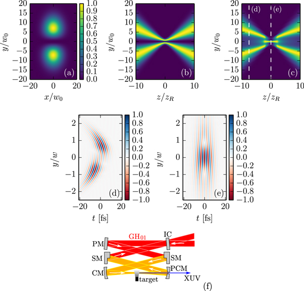
Figure 3. (a) beam profile of  at
at  (b) y–z-cut at x = 0 (c) same as (b) with π phase mask applied to one lobe in far field, where z is optical axis, w0 beam waist, zR Rayleigh range; data normalized for each z position (d) normalized time-dependent electric field of a 7 fs pulse in the
  plane after phase shift of π and an envelope delay of
  was applied to one lobe of the
  in far field (e) same in focal plane, showing wave front rotation (f) setup for a low-loss cavity with wave front rotation in the focus. IC: input coupler, PM: plane highly reflective mirror, SM: highly reflective mirror with step, CM: curved highly reflective mirror, PCM: pierced highly reflective curved mirror.
Download figure:
Standard image High-resolution imageProduction of IAPs by NOG was only experimentally demonstrated with sub-two-cycle pulses [62]. However, [61] predicts that separation of an IAP is still possible with 
 pulses at
  , which corresponds to 3.75 cycles, assuming a harmonic beamlet divergence angle of
  , with
  denoting the divergence angle of the driving beam. As we show later, it is possible to obtain a significantly smaller beamlet divergence by placing the target before the focus, so non-collinear generation of IAPs at pulse durations realistic in cavities may come into reach.
The maximum crossing angle for efficient NOG is only  [61]. This means that in the two-cavity and the three-focus approach, the curved mirrors next to the target have to be placed as close as possible to each other to avoid losses due to truncation of the mode. Reflection on a mirror cropped by a straight line in a distance of
  from the center ideally leads to a round-trip loss of
  . The same holds for gating by an external pulse, but in that case one can choose to truncate the intracavity beam less and the external beam more to allow for a better power enhancement. TMG does not suffer from truncation losses, however care must be taken that the distortion introduced by the first delay mirror is compensated well by the second one without introducing too much loss. As it will be shown later, these losses can be kept small if the delay mirrors are placed appropriately.
Commonly, the resonator length and the seed repetition rate must be actively stabilized with respect to each other to maintain constructive interference of the carrier of the seed pulse with the carrier of the circulating pulse. Likewise, for NOG, sub-wavelength precision and stability of alignment are necessary for constructive interference of the two beams in the intersection point. From all presented NOG variants, TMG appears to be the most stable, because the delay between the beams is implemented monolithically. So, from the point of view of truncation losses and experimental effort, TMG can be considered the most promising variant for intracavity NOG.
In conclusion, we reviewed possible schemes for intracavity production of IAPs and identified two promising approaches (CMC-PG and TMG) and we found significant reasons to prefer them over the remaining schemes. In the remainder of the paper, we aim at performing a fair comparison of polarization gating with TMG. For this, we optimize both gating methods for optimum photon flux using the same target parameters and considering the same technical restrictions.
3.2. Criteria for a fair comparison of viable gating schemes
For a fair comparison of the two considered gating schemes for cavity-enhanced HHG, we need to optimize the parameters of both methods for optimum photon flux, demanding the same minimum intensity contrast ratio of the IAPs and taking into account the same technical restrictions, as discussed in section 2, i.e., limited seed pulse energy, cavity losses, gas flux, beam waist, beam diameter on the curved mirrors and damage intensity. We optimize for output coupling through a hole (for CMC-PG) and a slit (for TMG) in the mirror following the focus, because geometrical output coupling does not angularly disperse the harmonic radiation, works over a broad bandwidth and it is suitable for high photon energies.
For each scheme, we identify parameters affecting the contrast ratio and perform a broad scan on them, which is enabled by the approximations and optimizations of the implemented computational model. Based on these parameters, we optimize the phase matching conditions and the output coupling. Accounting for losses to the circulating pulse by nonlinear effects in the gas target, we obtain a complete set of optimum parameters, allowing us to simulate the optimum case with a minimum number of approximations.
To be consistent, we need to impose the same contrast ratio for both schemes. Having in mind time-resolved photoelectron emission spectroscopy (PES) and microscopy (PEEM) applications, in the broad parameter scan we optimize for IAPs with an intensity contrast ratio better than 10 after spectral filtering for harmonic orders between 74 and 84 (88.2– ), which is about the minimum required photon energy for time-resolved PEEM experiments. In the following step of optimizing the phase matching, we only require a contrast ratio of 6.66 to make sure that promising results are not excluded due to numerical deviations, e.g., due to neglecting propagation effects in the broad parameter scan.
We restrict the study to HHG in neon, which was already shown experimentally in ECs and is a suitable choice for the targeted photon energy range due to its high ionization potential.
3.3. Polarization gating
In the CMC-PG scheme, the contrast ratio is affected by the delay  of the multi-order quarter-wave plate, the CEP
  of driving pulse and the incidence angle
  on the polarizing optic. Parameters affecting the photon flux are the target position z0, the target length L, the atomic density n of the target gas, the driving pulse energy EIR and the focusing w0, which affect the phase matching, and the hole diameter d for the output coupling.
In a first step, we optimize the parameters affecting the contrast ratio. For this, we compute the single-atom dipole response, scanning the delay  from 0 to
  in 1
in 1  steps, the carrier-envelope phase
  from 0° to 180° in 5° steps and the incidence angle
  from 73.5° to 90° in 1.1° steps. This interval of incidence angles already covers all reflectance ratios and smaller angles would only result in higher losses to the p-polarized component (see figure 4). The long trajectory is suppressed by restricting the electron excursion time to values below 0.66 driving field periods, and the peak intensity is chosen to be
  in each case. For each parameter set, we compute the conversion efficiency
  , where d(t) is the single-atom dipole response envelope after a bandpass from harmonic order 74–84 and IIR is the driving field intensity. The contrast ratio, i.e. the ratio between the global and the secondary maximum of
  , is also computed. Figure 5(a) shows that there is a tradeoff between the conversion efficiency and the contrast ratio. Choosing the parameter set with best efficiency and a contrast ratio
  , we obtain an incidence angle
  , a delay
  and a CEP of
  , resulting in a contrast ratio of 10.5 (see figure 5(b)). The energy loss at the polarizing optic is
  , i.e.
  of the seed energy is available to the cavity.

Figure 4. Reflectance off a silicon plate for the s-polarized (solid line) and p-polarized (dashed line) components versus incidence angle, at a wavelength of  . The dotted line shows the ratio of the reflectances.
Download figure:
Standard image High-resolution image
Figure 5. CMC-PG in neon with  pulses at 3 × 10¹⁴ W cm–2,
  . (a) Tradeoff between contrast ratio and conversion efficiency. Each point represents one parameter set of the scan. The dashed line marks the contrast ratio 10 and the diamond marks the parameter set shown in the right panel (b) attosecond pulse train from single-atom dipole response, bandfiltered from H74 to H84, interpolated and squared.
Download figure:
Standard image High-resolution imageAfter having determined the parameters for the optimum contrast ratio of the single-atom dipole response, the next step is to optimize the parameters affecting the phase matching (z0, L, EIR, w0, n). The scaling law introduced in [64] states that a parameter set z0, L, EIR, w0, n is equivalent to a parameter set  ,
,  ,
,  ,
,  ,
,  , where η is an arbitrary number and the XUV photon flux also scales with
  . This allows us to eliminate one parameter by using the following scale-invariant parameters: relative target position
  , driving field peak intensity I, relative gas density
  and relative target length
  , where
  is the Rayleigh range. The scale-invariant quantities corresponding to the pulse energy E and the XUV photon flux
  are the relative pulse energy
  and the relative XUV photon flux
  .
.
To enable a parameter scan on such a broad parameter range, which requires computing the single-atom dipole response on a spatial grid for each parameter set, we resort to several approximations and optimizations: first of all, we exploit rotational symmetry. The relative target length  is successively increased and the far-field on-axis harmonic peak intensity is calculated. This intensity will typically first increase with increasing target length and then decrease when the phase matching length is exceeded. The calculations stop when the intensity drops to 75% of the maximum or when
  exceeds 1. We only save the harmonic spectra from H74 to H84 and discard the rest of the spectrum. We vary
  from −1 to 1 in steps of 0.1, the peak intensity from
  to
to  in
in  steps, and
  from
from  to 0.5 × 10⁻³ nstdm, using
  steps. The step size in the direction of the optical axis is chosen as
  .
.
For each set of scale-invariant parameters, we compute the driving field and the XUV radiation incident on the output coupling mirror. Then we also scan the relative output coupling hole diameter d/w from 0.1 to 0.6 in steps of 0.05, where w is the driving beam radius at the output coupling mirror. This determines the output coupling efficiency as well as the losses of the circulating pulse at the pierced mirror ( for
for  ).
).
Using the driving field on the output coupling mirror and the losses at the pierced mirror, we compute the achievable pulse-energy enhancement (see
As we are interested in the parameters with optimum photon flux, we apply the scaling law to each parameter set, increasing the focus size to the maximum without violating any of the technical restrictions (gas flux, beam waist, beam diameter, peak intensity), and without requiring more than the available seed pulse energy. Of the assumed input pulse energy of  , a fraction of
  is lost at the polarizing optics of the gating scheme, leaving a pulse energy of
  to seed the cavity. We only allow target lengths with a resulting contrast ratio better than 6.66. The obtained optimum parameters are a peak intensity of
  , an atomic density of
  , a beam waist of
  , a target length of
  , target position at
  and a hole diameter of
  , leading to an estimated pulse-energy enhancement of 97.2 (considering nonlinearities). The curved mirrors must be placed at a distance of at least
  from the focus in order to not exceed the assumed damage threshold.
With the optimum parameters, we repeat the simulation without suppressing the long trajectory. The resulting time-domain XUV intensity on output coupling mirror is shown in figure 6. The contrast ratio of the output coupled, spectrally filtered XUV radiation is 7.82.

Figure 6. (a) Far-field XUV intensity versus time and transverse coordinate for CMC-PG with optimum parameters after spectral filtering from H74 to H84 and interpolation, in arbitrary units. The dashed line marks the radius of the hole in the output coupling mirror. (b) Output coupled XUV radiation, integrated over the hole (solid line) and the full transverse coordinate (dotted line, scaled by  ).
).
Download figure:
Standard image High-resolution image3.4. Transverse mode gating
Like with polarization gating, the achievable contrast ratio is affected by the delay  and CEP
  . Moreover, the relative target position
  affects the XUV beamlet divergence angle [65] and thus the separation of harmonic bursts in the far field, so it is also an important parameter for the contrast ratio. As before, the parameters affecting the photon flux are L, EIR, w0 and n, as well as the width d of the slit in the output coupling mirror.
As a first step, we again determine the optimum parameters for the contrast ratio. Here, it is not sufficient to only compute single atom dipole responses, because transverse effects (beamlet divergence) must be accounted for. Therefore we compute the XUV far field in the limit on an infinitesimally thin gas target, scanning  from 0 to
  in 1
in 1  steps and the relative target position from −1.3 to 1.3 in steps of 0.1, again at a fixed peak intensity of
  . To reduce computation time, we use the short-trajectory envelope approximation for the dipole response around H79, and only consider one transverse direction: the one along which the harmonic bursts are angularly separated. For each parameter set, we compute the time-dependent on-axis XUV far field. Because the envelope approximation only yields spectral components in a narrow bandwidth around the targeted H79, this time-dependent field does not exhibit the individual bursts of an attosecond pulse train, but rather represents an envelope over the pulse train. From this envelope E(t), we can compute the contrast ratio of the attosecond pulse train, i.e. the ratio between global maximum and secondary maximum, which is expected at least one half-cycle before or after the global maximum, as

where t0 is chosen so that  is maximal and
  the duration of a half-cycle. We also compute a conversion efficiency measure by relating the peak intensity of the XUV field with the necessary IR pulse energy:

Figure 7(a) shows the tradeoff between these two quantities. Choosing the parameter set with best efficiency and contrast ratio  as before, we get a target position of
  and a delay of
  , resulting in a contrast ratio of 19.3 (figure 7(b)).
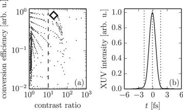
Figure 7. Transverse mode gating (TMG) in neon with  pulses at
  ,
,  . (a) Tradeoff between contrast ratio and conversion efficiency. Each point represents one parameter set of the scan. The dashed line marks the contrast ratio 10 and the diamond marks the parameter set shown in the right panel (b) envelope over attosecond pulse train from single-atom dipole response, interpolated and squared. The distance between the dotted lines is one half-cycle.
Download figure:
Standard image High-resolution imageFor the parameters of optimum contrast ratio, we optimize the phase matching parameters L, EIR, w0 and n by scanning the scale-invariant parameters  , I and
  . We compute in 3 + 1D, exploiting reflectional symmetry in one spatial direction, and use envelope approximations for the driving field source terms as well as the short-trajectory envelope approximation for the XUV. As in the case of polarization gating, we only consider relative target lengths
  and only compute until the photon flux (peak of the time-dependent on-axis far field) decreases to 75%. We vary the peak intensity and the relative gas density in the same parameter range.
For each set of scale-invariant parameters, we compute the driving field and the generated XUV radiation in the output coupling mirror plane. Then we scan the relative slit width d/w from 0.01 to 0.10 in steps of 0.01, where w is the radius of the driving beam on the mirror. For  , the round-trip loss is still below
  . Figure 3(c) shows that the on-axis minimum of the GH01 mode in the far field is conserved if a phase shift is introduced to one lobe far from the focus, i.e. the circulating mode has an intensity minimum at the position of the slit, which explains the low losses. Thus, for these slit widths the loss is still not a limiting factor. However, the slit also serves to spatially separate one of the angularly dispersed harmonic beamlets. Increasing the slit size further would make it impossible to reach a good contrast ratio, as the results of the parameter scan will show later.
As for polarization gating, for each resulting parameter set we compute the necessary relative seed pulse energy and relative output-coupled photon flux, accounting for cavity round-trip losses, phase shift and output coupling efficiency. After that, we apply the scaling law to maximize the photon flux in each case without violating the same technical restrictions as in polarization gating, requiring a contrast ratio better than 6.66 and permitting  of
of  as seed pulse energy, where
  is the maximum achievable overlap of a GH00 seed with the GH01 resonator eigenmode using a phase mask [66]. The resulting optimum parameters are a peak intensity of
  , an atomic density of
  , a beam waist of
  , a target length of
  and a slit width of
  , leading to an estimated pulse-energy enhancement of
  . The distance between focus and curved mirror must be larger than
  to avoid damage.
For the optimum parameters, we repeat the simulation without envelope approximations and considering both trajectories. The resulting time-domain XUV intensity evolution on the output coupling mirror is shown in figure 8, where a clear lighthouse effect can be seen which allows the separation of an IAP by spatial filtering at the slit. We observe that the contrast ratio can be improved if not only the slit width but also the slit length is limited; when choosing a  slit the contrast ratio of the output coupled, spectrally filtered XUV radiation is 7.0. This can most likely be attributed to the larger divergence angle of the long-trajectory contribution to the harmonic far field. It can be seen that the harmonic beamlet divergence is on the order of
  —this explains the good angular separation of harmonic bursts even with 17.5
  pulses.
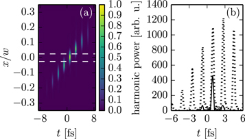
Figure 8. (a) Far-field XUV intensity versus time and transverse coordinate for transverse mode gating (TMG) with optimum parameters after spectral filtering from H74 to H84 and interpolation, in arbitrary units. The dashed line marks the slit radius of the output coupling mirror. (b) Output coupled XUV radiation, integrated over a  slit (solid line) and the full transverse plane (dotted line); power axis as in figure 6.
Download figure:
Standard image High-resolution image4. Discussion
4.1. Comparison of TMG and polarization gating
Comparing figure 5(a) with figure 7(a), it can be seen that the trade-off between contrast ratio and conversion efficiency is much more critical in the CMC-PG scheme than in the TMG scheme. Also, the resulting XUV peak intensity is 135.7 times higher for TMG after optimizing under the previously specified contraints.
There are several reasons for this: in the CMC-PG scheme, only  of the seed energy is available, because one polarization direction must be suppressed, whereas in TMG up to
  of the seed energy can be coupled into the cavity assuming optimum mode matching. Further, the resonator mode excited in TMG has an on-axis minimum in the middle of the output coupling mirror, leading to lower round-trip losses of the circulating pulse. Then, to reach the required contrast ratio, the delay for polarization gating must be chosen
  while it is only
  for TMG. Due to the larger delay, more pulse energy or a tighter focusing is needed to reach the same peak intensity in the focus, which results in a lower efficiency. Finally, the output coupling efficiency (fraction of the XUV power transmitted through the orifice to the whole XUV power incident on output coupling mirror, computed at the peak of the IAP) is
  for CMC-PG, but
  for TMG—for optimum beamlet divergence and thus optimum output coupling efficiency, the target has to be placed approximately one Rayleigh length before the focus, which is not possible in the case of CMC-PG because the necessary peak intensity can not be reached there due to the longer delay.
For these reasons, TMG can be regarded as the preferred method for implementation.
4.2. Photon flux estimation for TMG
To estimate the photon flux that can be obtained with the TMG scheme, assuming the determined optimum parameters, we also simulate HHG with the parameters of the reference experiment [13], using the same approach applied to obtain figures 6 and 8, and compare. The number of XUV photons produced per pulse (in the spectral range from H74 to H84) can be obtained by integrating the harmonic power over time and is 1.8 times higher for the simualted TMG case than in the simulated reference experiment. From this we can conclude that a similar photon flux as in the reference experiment ( ) can be obtained with TMG. However, it is important to note that the photon flux in the reference experiment was strongly limited by cumulative effects in the gas target due to the high repetition rate of
  [13] and that these cumulative effects were not included in the model. Therefore, the predicted photon flux should be regarded as a rather strong underestimation of the flux attainable with implementing this scheme at a repetition rate at which each gas atom is hit by a single pulse only. With state-of-the-art lasers operating at the highest repetition rates in this regime [29] and a pulse-energy-scalable compression scheme (e.g. [67]), the seed pulse energy can be increased accordingly. The scaling law of [64] allows to change the geometry of the EC setup such that the same total photon flux can be obtained at a significantly lower repetition rate, without violating the constraints of beam waist and peak intensity as given in section 2. The beam diameter on the curved mirrors and therefore the size of the substrates may have to be increased, however. The maximum allowed gas flux is not exceeded because the flux is scale-invariant if the nozzle size is only scaled in transverse direction. Therefore, scaling to lower repetition rates is possible without reducing the XUV photon flux.
Decreasing the repetition rate to a value where cumulative effects do not play a role anymore promises considerably better photon flux than demonstrated in [13]. For instance, gas flow simulations predict that at  and for typical beam waists, each atom is only hit by a single pulse.
5. Conclusions
In conclusion, we theoretically investigated possible time gating methods for the enhancement-cavity-assisted generation of isolated XUV attosecond pulses within the constraints of state-of-the-art laser technology. In particular, we identified polarization gating and TMG, a new method combining the ideas of NOG with higher-order mode output coupling, as viable gating methods for intracavity generation of IAPs. We presented an algorithm optimizing all relevant parameters for intracavity HHG in order to obtain optimum photon flux, considering the various trade-offs among finesse, focusing and the position, density and size of the gas target, and output coupling orifice size in the case of geometric output coupling, and applied it for a fair comparison between TMG and polarization gating. TMG is identified as the preferred method in terms of the photon flux and trade-off between efficiency and IAP contrast ratio. In contrast to other supposable intracavity non-collinear gating schemes, the delay in TMG is alignment-free and intrinsically stable because it is introduced by a monolithical step mirror.
We showed that using this scheme and taking advantage of state-of-the art technical advances, IAPs at a photon energy and flux sufficient for time-resolved PES and PEEM experiments can be expected. Scaling laws predict that this photon flux can be achieved at repetition rates compatible with time-of-flight spectrometers when using non-circular gas nozzle orifices and sufficiently large mirror substrates. Given the recent advances of power scaling in resonators [12], broadband cavity mirrors [20], high-power phase-stable Yb-based seed lasers [29], and zero-offset-frequency resonators [30], the implementation of efficient, cavity-enhanced generation of IAPs comes into reach. Compared to state-of-the-art  sources of IAPs, the dramatic increase in repetition rate will have a corresponding impact on the signal-to-noise ratio in experiments in attosecond physics, promising to reveal nanoscopic information so far hidden under the measurement noise floor [8]. Equivalently, with such a source, the measurement time can be dramatically reduced, rendering applications which so far have been prohibited by long acquisition times, feasible. Just to name an example, the time-resolved investigation of the spatial dynamics of plasmonic fields in nanostructures, combining attosecond streaking with PEEM, comes into reach with such a source [6, 7].
In addition, such a source would constitute an XUV frequency comb with unique properties for precision spectroscopy [14, 15]: the high repetition rate corresponds to a high spacing between the comb lines, increasing the power per line. Furthermore, while common cavity-based XUV frequency combs are only available in small spectral ranges around the odd harmonic orders, such a source would allow precision spectroscopy over a broad spectral continuum.
Acknowledgments
This research was supported by the Fraunhofer Society/Max-Planck Society cooperation 'MEGAS'. Valer Tosa acknowledges partial support from UEFISCDI projects 03ELI-RO/2016 and RU-TE-2014-4-0425. We thank Simon Holzberger, Henning Carstens, Nikolai Lilienfein and Vladislav Yakovlev for fruitful discussions.
Appendix A.: Placement of delay mirrors in the TMG scheme
We show that WFR as discussed in section 3.1 and depicted in figure 3(e) can be achieved using a setup as shown in figure 3(f) without introducing significant round-trip losses. Our reasoning consists of three steps: first, we show that the same electric field distribution is obtained from a  mode irrespective of the position along the optical axis at which the phase mask is placed, as long as it is placed sufficiently far from the focus. Then, we show that this field distribution exhibits point symmetry around the focus. Finally, we show that in a setup like in figure 3(f), the phase masks are imaged into planes far enough from the focus. We begin with only considering the π phase mask and then generalize the result for an additional delay.
To examine the sensitivity of the desired field distribution with respect to the distance  between phase mask and focus, we first compute the
  mode numerically at the delay mirror position. We then add a constant phase to one lobe and propagate to a position zff far behind the focus. Now we can analyze how strongly the field at zff depends on
  . For this, we vary
  and compute the overlap of the field at zff with a reference field at the same position obtained with
  . Figure A1 shows that a good approximation to this reference field is already obtained if the delay mirror is placed at a distance
  before the focus, reaching overlap values better than 0.999 irrespective of the phase shift, which shows that losses are not significant for a targeted pulse-energy enhancement of ∼100.

Figure A1. Convergence to the single-lobe phase-shifted  mode for different values of the phase shift.
Download figure:
Standard image High-resolution imageFor the second step of showing the symmetry of the field distribution, we assume that the phase mask is placed at  and numerically compute the complex electric field amplitude
  for different z positions behind the phase mask. We then compute the overlap of
  with
with  . The overlap is 1 within numerical precision both for z positions far from the focus as well as near the focus.
As last step, we apply the mirror equation  to find out to which planes the step mirrors in figure 3(f) are imaged. Assuming
  , which is the case for the determined optimum parameters of TMG, and assuming that the step mirrors are placed at a distance
  from the curved mirrors, we obtain
  , i.e., the first step mirror is imaged to a plane far behind the focus. Given the symmetry shown in the last step, we can conclude that we indeed obtain a mode that is a very good approximation to the desired field distribution, with a overlap of 0.999. A similar argument can be applied to the compensating step mirror.
In conclusion, we have shown that a single-lobe phase shift can be introduced and compensated without significant round-trip losses. Now we look at the case when we also add a single-lobe delay. In the spectral domain, introducing a delay  corresponds to multiplication with a factor of
  , where
  , i.e., delaying one lobe is equivalent to applying a phase mask on each spectral component, with a frequency-dependent phase shift. Figure A1 shows that the overlap is even better for phase shifts
  , therefore the previous result can be generalized from phase-shifting to delaying one lobe.
Appendix B.: Approximation of the pulse energy enhancement
When traversing the gas target, the driving pulse is altered in its spectral (magnitude as well as phase) and spatial features due to the linear refractive index of the gas, the Kerr effect and plasma formation. This limits the overlap between the input and the intracavity beam and, therefore, the achievable pulse-energy enhancement. After performing the parameter scan to optimize phase matching for the CMC-PG and TMG schemes, we need to estimate the enhancement to compute the necessary seed pulse energy.
To arrive at a suitable approximation, we follow a similar approach as [19] and decompose the field that has passed the gas target into Gauss–Hermite modes, which are the eigenmodes of an empty resonator. We denote the driving field that has passed the gas target by  (e.g. in the plane of the output coupling mirror). In the case of TMG, we have to compensate the one-sided phase shift π and delay
  to arrive at a field
  that can be compared to the resonator eigenmode, and which, in the case of an empty cavity, is just equal to the eigenmode:

For CMC-PG, we just set  . Then, we decompose
  into the resonator eigenmodes:

where

and  are the normalized Gauss–Hermite modes. We can compare the coefficients
  with coefficients
  obtained with the same approach but for a driving field that is not altered by a gas target. Denoting the resonant mode with
  , with
  for CMC-PG and
  for TMG, we get
  for
for  . We compute the energy loss Lm to non-resonant modes by comparing the energy in the resonant mode after passing the gas target with the energy of an unaltered mode:
The total round-trip loss L is the sum of losses Lm to non-resonant modes, losses due to the hole in the output coupling mirror (twice the loss that is caused by transmission through the orifice, also due to coupling to non-resonant modes [68]) and the assumed  losses of the empty cavity.
The spectral phase shift  the pulse experiences while traversing the target can be computed by comparing the phases of the altered and the unaltered mode:

The choice of the cavity length and the position in the stability range (and of the EC mirrors [30]) allows to compensate for the spectral phase shift by a polynomial of first order. Therefore, we fit a first-order polynomial  to
to  (weighted by the spectral intensity) and subtract it to obtain the round-trip spectral phase shift

The round-trip phase shift and loss together allow us to choose the optimum input coupler reflectance r2 for maximum pulse-energy enhancement. Assuming a steady state in the cavity, the enhancement of a cavity seeded by CW light is [69]

To find a local maximum for ![$r\in [0,1]$](https://content.cld.iop.org/journals/1367-2630/19/3/033040/revision2/njpaa6315ieqn214.gif) , we compute the roots of
, we compute the roots of  , which are

Computing the enhancement E for  and
and  and choosing the higher one, requiring
 ![$r\in [0,1]$](https://content.cld.iop.org/journals/1367-2630/19/3/033040/revision2/njpaa6315ieqn218.gif) , yields the optimum pulse-energy enhancement and input coupler reflectance. To generalize to broad-band pulses, we apply this procedure for each wavelength and average over the results, again weighted by the spectral intensity.
, yields the optimum pulse-energy enhancement and input coupler reflectance. To generalize to broad-band pulses, we apply this procedure for each wavelength and average over the results, again weighted by the spectral intensity.
Appendix C.: Envelope approximation for the Kerr source term
Given complex envelope  , the electric field is
  . Neglecting terms oscillating at
  , which describe harmonic generation, (2) can be written as

with the source term envelope

Appendix D.: Envelope approximation for the plasma source term
For the plasma source term  , we employ the envelope approximation to (3) as suggested in [18]:

The source term envelope  can be computed from
 without resorting to finer time discretization.
Here,  denotes temporal Fourier transform, r0 is the classical electron radius,
  is the ionization fraction computed from cycle-averaged ionization rates,
  is the ionization rate at the electric field maximum of the cycle and I is the intensity.
Appendix E.: Envelope approximation for the XUV source term
We obtain an envelope approximation for the XUV source term by approximating the linearly polarized driving electric field locally by a CW field and then using precomputed dipole responses. This leads to a significant speedup in the calculation of the dipole response, because the envelope approximation allows coarser time discretization and the lookup of precomputed responses is fast.
We denote the harmonic dipole response obtained from the SFA with neglected ground state depletion for a cosine driving field  by
by  . Delaying the driving field by
  just delays the harmonic response correspondingly, therefore the dipole response for a delayed cosine driving field
  is
is  .
.
Now, provided that the complex driving field envelope  varies slowly compared to one cycle, we can approximate the driving field
  in the vicinity of
  by
by
which is a cosine field with the amplitude  , delayed by
  . The dipole response to such a CW driving field would be

Neglecting long-timescale effects like ground state depletion and considering that the time scale on which HHG happens, which is given by the electron excursion time, is typically below one cycle, we can use  as an approximation of the real dipole response d(t) in the vicinity of
  . Applying this approximation for all
  and selecting the contribution of a single harmonic order will lead us to an envelope approximation for the dipole response.
For convenience, we express the cosine dipole response for each amplitude as a Fourier series

where q is the harmonic order. The harmonic spectra cq (A) can then be precomputed for each amplitude A. Substituting yields

This formula allows to only consider the contribution dq (t) from a single harmonic order q by choosing only one term of the series:

Until now, we inherently assumed that HHG happens instantaneously. In reality, this is not the case—in the three-step model, the emitted electron travels some time before recombination happens. Further, the ground state of the atom gets depleted due to partial ionization. We can account for both effects in a limited manner by multiplying the dipole response by the squared absolute value of the ground state amplitude  , where
  is the ionization fraction, and introducing an artificial lag
  , which will in general depend on the harmonic order q and on the considered trajectory:

We can decompose dq
(t) into an envelope and a rapidly oscillating term,  , with

This envelope can be computed without the requirement of sub-cycle time resolution.
We verify the approximation by computing the dipole spectrum around H79 in neon for a  gaussian pulse with a peak intensity of
  . The CW spectra cq
(A) are precomputed with the SFA model with limited excursion time to suppress the long trajectory. We compute the dipole spectrum without envelope approximation, and the envelope approximation for H77, H79 and H81, which overlap due to the short pulse duration. As can be seen in figure E1, their superposition is a good approximation around H79, while the agreement gets worse further away because neighboring harmonics were not considered. The lag was chosen equally for the three neighboring harmonics to be
. The CW spectra cq
(A) are precomputed with the SFA model with limited excursion time to suppress the long trajectory. We compute the dipole spectrum without envelope approximation, and the envelope approximation for H77, H79 and H81, which overlap due to the short pulse duration. As can be seen in figure E1, their superposition is a good approximation around H79, while the agreement gets worse further away because neighboring harmonics were not considered. The lag was chosen equally for the three neighboring harmonics to be  , where T is the duration of one cycle, to get optimum overlap.
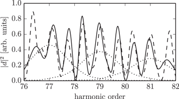
Figure E1. Dipole spectrum for a  ,
,  pulse in neon. The solid line is the dipole spectrum computed without envelope approximation; the dotted lines are envelope approximations of individual harmonics and the dashed line is their superposition.
Download figure:
Standard image High-resolution image
In the limit of long pulses, the envelope  can be regarded as the scaled envelope of an attosecond pulse train obtained by spectral filtering around the harmonic order q: for long pulses, the individual harmonics do not overlap. Then, the spectrum of dq
(t) is a good approximation to the spectrum of the SFA dipole response d(t) in the spectral range from harmonic order
can be regarded as the scaled envelope of an attosecond pulse train obtained by spectral filtering around the harmonic order q: for long pulses, the individual harmonics do not overlap. Then, the spectrum of dq
(t) is a good approximation to the spectrum of the SFA dipole response d(t) in the spectral range from harmonic order  to
to  . This also means that we can obtain dq
(t) by applying a bandfilter to d(t) around the harmonic order q with a bandwidth of two harmonic orders. In the time domain, after eliminating the oscillation with frequency
. This also means that we can obtain dq
(t) by applying a bandfilter to d(t) around the harmonic order q with a bandwidth of two harmonic orders. In the time domain, after eliminating the oscillation with frequency  , this bandfilter corresponds to a convolution with a half-cycle-long time window, therefore smoothing out the individual bursts of the attosecond pulse train d(t). We can conclude that
  is the smoothed-out version of the attosecond pulse train d(t), which is approximately proportional to the envelope of the pulse train if the individual bursts have similar pulse durations.