


Abstract
Recent explorations of topology in physical systems have led to a new paradigm of condensed matters characterized by topologically protected states and phase transition, for example, topologically protected photonic crystals enabled by magneto-optical effects. However, in other wave systems such as acoustics, topological states cannot be simply reproduced due to the absence of similar magnetics-related sound–matter interactions in naturally available materials. Here, we propose an acoustic topological structure by creating an effective gauge magnetic field for sound using circularly flowing air in the designed acoustic ring resonators. The created gauge magnetic field breaks the time-reversal symmetry, and therefore topological properties can be designed to be nontrivial with non-zero Chern numbers and thus to enable a topological sonic crystal, in which the topologically protected acoustic edge-state transport is observed, featuring robust one-way propagation characteristics against a variety of topological defects and impurities. Our results open a new venue to non-magnetic topological structures and promise a unique approach to effective manipulation of acoustic interfacial transport at will.
Export citation and abstract BibTeX RIS

Content from this work may be used under the terms of the Creative Commons Attribution 3.0 licence. Any further distribution of this work must maintain attribution to the author(s) and the title of the work, journal citation and DOI.
1. Introduction
While topology is a pure mathematic concept, it has now become a powerful freedom in designing physical systems and their intrinsic symmetries. For example, the conventional Landau symmetry breaking theory alone failed to describe recent developments in condensed matter physics such as the quantum Hall effect [1–6], where topological descriptions become crucial and the corresponding topological phases can be characterized by topological invariants such as Chern numbers. Remarkably, the local perturbation to the edge cannot affect bulk properties, due to the presence of topologically protected edge states at the interface between two media with different topological phases, which leads to the robust one-way edge state transport in recent emerging fields of Chern insulators [7–9] (systems with nonzero Chern numbers and associated with integer quantum Hall effects) and topological insulators [10, 11] (associated with quantum spin Hall effects). A typical condition to observe these unique topological phenomena is the broken time-reversal symmetry, e.g., by means of applied magnetic fields in the two-dimensional electron gas for the quantum Hall effect. Similarly, nontrivial photonic topological phases have also been demonstrated in a variety of photonic crystals based on magneto-optical materials in which time-reversal symmetry is broken with external magnetic fields [12–17]. Similar to the electronic system, the bands of photonic crystals can also be characterized by Chern numbers [13, 18], and gap Chern numbers [19], defined as the sum of the Chern numbers of all the bands below the photonic bandgap, can be used to describe the topological property of the corresponding photonic bandgaps. When such gap Chern number changes across an interface separating two media, there will exist gapless surface states with robust one-way light propagation against impurities and perturbations, characterizing the non-trivial topological properties of photonic crystals due to the breaking of the time reversal symmetry.
However, due to the absence of similar magnetics-introduced breaking of time reversal symmetry in acoustics [20, 21], it is therefore necessary to develop an effective strategy by which a gauge magnetic field can be created for acoustics to break the time-reversal symmetry of sound propagation, and acoustic metamaterials [22–29] or sonic crystals [30] may be exploited to solve this issue. Recently Alu et al proposed a good solution to solve the problem with a compact design [31]. They designed a circular structure containing flowing air, attached with three channels for signal input/output. When the air inside the ring is flowing circularly, the signal in any two channels of the device exhibits non-reciprocal propagation due to the broken time-reversal symmetry induced by an effective gauge magnetic bias, similar to the Zeeman effect observed in magneto-optical medium. In this paper, we propose to utilize the air-flow circulation [31] to break the time-reversal symmetry from the 'meta-atom' level and thus to control the fundamental symmetries in order to address this grand challenge. Specifically, we apply circulating air flow to a designed 'meta-atom'—an acoustic ring resonator—to spatially modulate the effective sound velocity in air. Similar to how circulating electrons produce magnetic field, the circulating air flow creates an effective gauge magnetic field that breaks the time-reversal symmetry of sound propagation. We further demonstrate a topological sonic crystal based on the ring resonators with circulating air inside, in which the gapless acoustic edge-state transport occurs in the band gap between two adjacent bands with nontrivial Chern invariants.
2. Time-reversal symmetry breaking due to air-flow circulation
In both topological electronic and photonic crystals and their associated quantum Hall effects, the external magnetic field is required to break the time-reversal symmetry. For example, the Lorentz force is induced by the magnetic field, such that electrons preferentially circulate only in one direction, as shown in figure 1(a). Similarly in an acoustic case, the clockwise air circulation applied to the acoustic ring cavity as shown in figure 1(b) creates an equivalent time-reversal symmetry breaking for sound. Intuitively, if the velocity of the clockwise air flow is  and the sound speed in air is
  the speeds of sound transiting through circulating air flow become different:
  for the clockwise and
  for the counter-clockwise directions, respectively. It is therefore obvious that sound transports with reverse phase shift in clockwise and counter-clockwise directions, leading to the time-reversal symmetry breaking. More rigorously, the wave equation for sound in such a circulating air flow can be expressed using an aeroacoustic [32] model,

where  is the velocity potential,
  is the angular frequency of sound, and
  is the density of air. Since the air flow is confined in the clockwise direction, the corresponding flow velocity only contains an azimuthal component,
  where
where  is the amplitude and
  is the azimuthal unit vector. As a result,
  and equation (1) can thus be simplified as

where the term  represents the scalar potential, while
  denotes [33] the vector potential, showing an effective magnetic field in such a non-magnetic structure due to the introduced circulating air flow. As a result of the existence of such non-zero vector potential, sound circulating inside the resonator experiences a phase shift if taking different paths, similar to the well-known Aharanov–Bohm effect. For example, between two points Q and P in the resonator in the inset of figure 1(b), the additional phase due to the vector potential is
  when sound travels from Q to P, whereas it becomes
  from P to Q. Because the selected paths are
  the additional phases become
  This vector potential-enabled phase difference clearly shows the breaking [2, 15] of time-reversal symmetry if simply reversing the sound propagating direction, i.e. the time-reversal symmetry and reciprocity are simultaneously broken for sound transport in such air-flow-circulated acoustic ring resonator.

Figure 1. Time-reversal symmetry breaking due to air-flow circulation. (a) Illustration of the mechanism of gyromagnetic materials showing the precession of the magnetic moment M of the electron e under the magnetic field B. (b) Illustration of the air-flow-circulated ring resonator containing clockwise flowing air of speed V with broken time-reversal symmetry similar to gyromagnetic materials. The inset shows an arbitrary propagation path of acoustic waves inside the ring.
Download figure:
Standard image High-resolution image3. Topological sonic crystal made of air-flow-circulated units
The topological sonic crystal we propose here is constructed with a graphene-like or honeycomb lattice [34] as depicted in figure 2(a) using the acoustic 'meta-atoms' demonstrated above. The graphene-like structure is to introduce the deterministic Dirac-like degeneracy at the boundaries of the Brillouin zone due to the intrinsic three-fold rotation symmetry of honeycomb lattice. In the designed topological sonic crystal, the neighboring rings are connected by non-circulated subwavelength waveguides ( in which only the acoustic plane wave (i.e. the fundamental waveguide mode) is supported in the studied frequency range (figure 2(b)). The lattice constant of the honeycomb-lattice sonic crystal is chosen to be
  for potential applications related to audible sound. The inner and outer radii of the ring resonators are
  and
and  respectively. The corresponding band structures with and without the circulating air flow, i.e.
  and
and  respectively, are shown in figure 2(c). It is clear that the degeneracies of a Dirac point at
  or
or  and two quadratic degenerate points at
  are lifted due to the time-reversal symmetry breaking caused by the circulating air flow. Such degeneracy lift leads to Chern number exchange of adjacent acoustic bands and their associated special topological states.
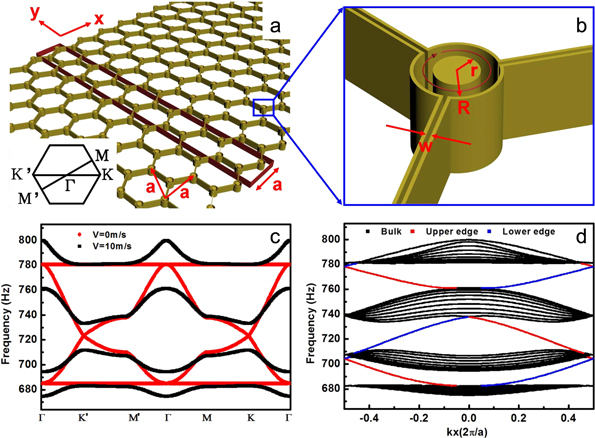
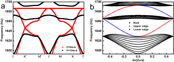
Figure 2. Topological sonic crystal made of air-flow-circulated units. (a) Illustration of the sonic crystal consisting of the air-flow-circulated ring resonators. The supercell (highlighted by the red rectangle) is selected to calculate the projected frequency band along the zigzag edge and the inset shows the first Brillouin zone. (b) The zoomed-in illustration of the detailed structural parameters. (c) The bulk frequency bands of the sonic crystal without air flow (V = 0, denoted by red circles) and with clockwise air flow (V = 10 m s−1, denoted by black squares). (d) The projected frequency bands of the sonic crystal with clockwise air flow (V = 10 m s−1) along x direction (zigzag edge). See appendix
Download figure:
Standard image High-resolution image4. Tight-binding model to calculate the Chern numbers
Here, we employed the tight-binding approximation theory to analyze the Chern numbers of two bands around the Dirac point, e.g., at 723 Hz, by recasting equation (2) into the Dirac equation. In the tight-binding model, each ring resonator directly couples to the nearest neighbor through the subwavelength waveguide. As a result, such coupling is not affected by the introduced air flow and its resulted vector potential, leading to the first-neighbor coupling coefficient of  without any additional phase shift. The outer rings can only be coupled through the adjacent neighbor rings in which the air flow induces an additional phase shift due to the vector potential, leading to the second-neighbor coupling coefficient of
  where the additional phase term is expressed as [2]

where is the total effective flux through an acoustic ring,
  is the effective flux occupied by the second-neighbor hopping path (only one third of an acoustic ring due to the three-fold rotation symmetry), and
  is the propagation phase of the mth-order azimuthal mode [31] in the ring resonator. Therefore, the Hamiltonian based on location wave functions of the two atoms in each unit cell of the graphene-like structure in the vicinity of the
  and
and  point can be expressed as [2]
  and
and  (see appendix
  and
and  are small quantities associated with the wave vectors
  expanded near the Dirac point at
  (
( is the angle between the vectors
  and
and  Based on the eigen vector
  of the Hamiltonians, the resulted Berry phase near the Dirac point can be derived with its definition
  The total Berry phase of the lower frequency band including the contributions from phase changes of both
  and
and  denoted as
  and
and  becomes
  which can be further simplified as
  due to the very small
  and
and  Hence, the topological invariant of the gap Chern number [13, 19] associated with the bandgap induced by the time-reversal symmetry breaking is

In the discussed frequency range around 723 Hz, the dipole mode of the ring resonator (see figure C1(a) in appendix  and according to equation (3) (defining
  in the case of clockwise air flow)
  is obtained consequently leading to
  associated with the bandgap around the Dirac degeneracy at
  or
or  Similarly the gap Chern number of −1 can also be obtained for the other two bandgaps around the quadratic degeneracies at
  analogous to the photonic counterpart [35]. Therefore, in our sonic crystal, the Chern numbers associated with the 4 bulk frequency bands can be easily calculated: −1, 0, 0, 1, respectively (from lower to upper bands in figure 2(c)). The obtained nonzero Chern invariants clearly indicate the nontrivial topological properties of the designed sonic crystal due to the degeneracy lift around the Dirac and quadratic degeneracy points.
5. Robust one-way acoustic edge modes
A signature of topological states is the presence of topologically protected gapless edge states inside the bulk frequency band gap at the interface between two media with different topological phases. In our design, such edge states exist by placing the air-flow-circulated graphene-like sonic crystal next to a rigid boundary (figure 2(a)). Since they possess different gap Chern numbers (for example, −1 for the sonic crystal and 0 for the rigid boundary) and the local topological perturbations due to the rigid boundary cannot affect the bulk properties of the sonic crystal, the topological phase transition occurs at the interface, leading to the continuous spectra of the gapless edge states with the neutralized Chern numbers inside the bulk frequency band gap of the sonic crystal, as shown in figure 2(d) where the projected frequency dispersion of the zigzag edge state is calculated. It is worth noting that the obtained topology-protected property is attributed to the bulk topological invariants across the interface and the number of the supported edge-modes is consistent with the corresponding difference in gap Chern numbers between adjacent materials. Since gap Chern number is the acoustic/photonic analogue [13] of Hall conductance whose sign denotes the transport direction of edge currents in integer quantum Hall effect, similarly the sign of the gap Chern number difference can also indicate the propagation direction of the supported edge mode. In our case the topological sonic crystal with  is surrounded by a rigid wall with
  leading to a negative sign of gap Chern number difference, which indicates a counterclockwise propagation of edge modes along the interface, corresponding to a rightward (+x) propagation of the lower edge mode (blue lines in figure 2(d)) and a leftward (−x) propagation of the upper edge mode (red lines) respectively.
We performed finite element simulations to examine the properties of the edge mode supported by the designed topological sonic crystal. Figure 3 shows the sound transport of the edge mode with the edge of the sonic crystal terminated at different locations. If the graphene structure is well preserved at the edge (i.e. the zigzag edge) (figure 3(a)), the expected unidirectional counterclockwise sound transport is clearly observed: sound propagates from right to left at the upper edge, but travels from left to right at the lower edge, well consistent with the theoretical predictions in figure 2(d). Although how we geometrically determine the edge of the sonic crystal leads to different geometrical forms and may slightly modify the acoustic dispersion of the edge [36], the global topological property of the sonic crystal is still maintained. The edge mode intrinsically supported by different topological phases between two different media therefore remains, for example, with the armchair edge (figure 3(b)) and the bearded edge (figure 3(c)) (see appendix
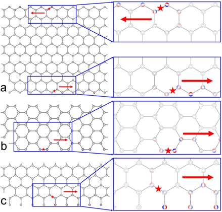
Figure 3. One-way acoustic edge modes. (a) The velocity–potential field distribution of the upper and lower unidirectional zigzag edge mode at 770 Hz with clockwise air flow (V = 10 m s−1). The red star shows the position of the acoustic source and the arrows show the propagation direction. The color from blue to red represents the value from minimum value to maximum value. (b) And (c) the velocity–potential field distribution of the propagating edge mode along the lower (b) armchair and (c) bearded edge at 770 Hz with clockwise air flow (V = 10 m s−1). The insets show the zoomed-in field distributions.
Download figure:
Standard image High-resolution imageSuch sound transport robustness of the edge mode of the topological sonic crystal remains even if a variety of interface defects are introduced. This is because the system is immune to any backscattering, which is topologically forbidden with nonzero gap Chern numbers as shown in figure 2(d). Here, we introduced four types of interface defects and investigated their effects on the edge mode of the topological sonic crystal: a vacuum void formed by removing one ring resonator (figure 4(a)), a strong local dislocation in the lattice (figure 4(b)), an exaggeratedly enlarged ring resonator (figure 4(c)), and a random-shaped object hidden inside an enlarged circle (figure 4(d)). Remarkably, sound transport is immune to backscattering by self-detouring around the disordered region or reorganizing the field distribution in the local defects. It is therefore evident that the supported edge-mode is robust against a large number of defects, which is a universal characteristic caused by the intrinsic topological feature of the topological sonic crystal and its enabled topological protection. It should be noticed that in the simulation above the air flow is well-isolated within each ring, and does not leak to neighbors through the coupling waveguides. The inter-cell flows may slightly modify the dispersions of the frequency bands but won't change the topological properties of the associated bands, and our further simulation (see appendix

Figure 4. Robust one-way acoustic edge modes. The velocity–potential field distribution of the acoustic edge mode along the lower zigzag edge robust to interfacial defects caused by (a) removing one ring, (b) moving one ring's position, (c) enlarging one ring's size, and (d) hiding one arbitrary-shape object inside the enlarged circle. The excitation frequency is chosen to be 770 Hz with clockwise air flow (V = 10 m s−1). The red star shows the position of the acoustic source and the arrows show the propagation direction. The color from blue to red represents the value from minimum value to maximum value.
Download figure:
Standard image High-resolution image6. Discussion
In summary, we have designed a topologically protected sonic crystal by using air-flow-circulated unit cells. Such topological acoustic phenomenon originates from the broken time-reversal symmetry caused by effective gauge magnetic field of circulating air flow and its related nontrivial topological properties with non-zero Chern numbers. Interestingly, the corresponding topological Chern number is relevant to the azimuthal order of the resonant mode in the ring resonator. For example, the topological Chern properties in the study above are within the frequency range around 770 Hz and with the azimuthal order of 1 for the resonant mode in the ring. If the frequency range is doubled (see appendix
Acknowledgments
The work was jointly supported by the National Basic Research Program of China (Grant No. 2012CB921503, and No. 2013CB632702) and the National Nature Science Foundation of China (Grant No. 11134006, No. 11474158, and No. 11404164). We also acknowledge the support of Natural Science Foundation of Jiangsu Province (BK20140019) and the support from Academic Program Development of Jiangsu Higher Education (PAPD).
Appendix A: The bulk and projected frequency bands with smaller V (V = 3 m s−1)
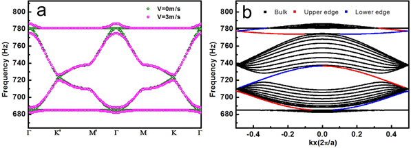
Figure A1. (a) The bulk frequency band of the sonic crystal without air flow (V = 0, denoted by green circles) and with clockwise air flow (V = 3 m s−1, denoted by magenta circles). (b) The projected frequency band of sonic crystal with clockwise air flow (V = 3 m s−1) along the x direction (zigzag edge). The blue and red lines correspond to the lower and upper edge states, respectively.
Download figure:
Standard image High-resolution imageAppendix B: The derivation of the Hamiltonian  without air flow
In the honeycomb-lattice sonic crystal, rings are located at positions  where
where  runs for all the lattice vectors (
 and
and  are basic lattice vectors, where
  is the lattice constant,
  and
and  are unit vectors in x and y direction) and
  (
( runs for the two rings within the unit cell. Because of the axial symmetry, the Hamiltonian based on location wave functions of the two rings in each unit cell can be written as
  in which
 ![$\varepsilon ={{E}_{0}}+\int [\sum n \sum \alpha {{\hat{q}}_{n\alpha }}(\vec{r})\delta (\vec{r}-{{\vec{R}}_{n\alpha }})-{{\hat{q}}_{n\alpha }}(\vec{r})\delta (\vec{r}-{{\vec{R}}_{01}})]\psi *(\vec{r}-{{\vec{R}}_{01}})\psi (\vec{r}-{{\vec{R}}_{01}}){\rm d}\vec{r}$](https://content.cld.iop.org/journals/1367-2630/17/5/053016/revision1/njp513017ieqn73.gif) indicates the on-site energy of the ring at
indicates the on-site energy of the ring at  (
( is the eigen value of a single unit cell), while the overlap integrals
 ![${{t}_{a}}={{t}_{1}}={{{\rm e}}^{-{\rm i}\vec{k}\cdot ({{{\vec{R}}}_{01}}-{{{\vec{R}}}_{02}})}}\int [\sum {{R}_{n}} \sum \alpha {{\hat{q}}_{n\alpha }}(\vec{r})\delta (\vec{r}-{{\vec{R}}_{n\alpha }})-{{\hat{q}}_{n\alpha }}(\vec{r})\delta (\vec{r}-{{\vec{R}}_{01}})]{{\psi }^{*}}(\vec{r}-{{\vec{R}}_{02}})\psi (\vec{r}-{{\vec{R}}_{01}}){\rm d}\vec{r}$](https://content.cld.iop.org/journals/1367-2630/17/5/053016/revision1/njp513017ieqn76.gif) (
( is the reciprocal lattice vector),
  and
and  indicate the hopping terms between the ring at
  and three nearest ones at
 and
and  where
where  represents the operator of local potential. Consequently, we obtain
  Further expanding
  near the K point and removing the energy origin point, we finally come to the Dirac equation:
  in which
  and
and  (
( are x and y components of the vector
  (
( is the angle between the vectors
  and
and 
 is proportional to the nearest coupling term,
  and
and  are Pauli matrices, and
  represents the amplitudes of two degenerate Bloch states at one of the corners of the hexagonal first Brillouin zone.
Appendix C: Different azimuthal modes of the ring resonator
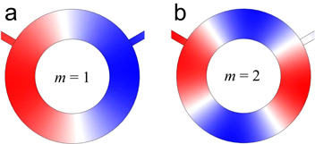
Figure C1. The velocity–potential distribution of the (a) dipole and (b) quadrupole mode of the ring resonator corresponding to the azimuthal order m = 1 and m = 2, respectively. The color from blue to red represents the value from minimum value to maximum value.
Download figure:
Standard image High-resolution imageAppendix D: The projected frequency bands of the armchair and bearded edges
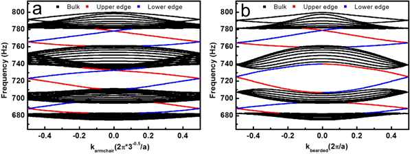
Figure D1. The projected frequency bands of (a) armchair and (b) bearded edges with clockwise air flow (V = 10 m s−1). The blue and red lines correspond to the lower and upper edge states respectively.
Download figure:
Standard image High-resolution imageAppendix E: Simulation consideration of the inter-cell flows in the waveguides and the inhomogeneous flow in the rings
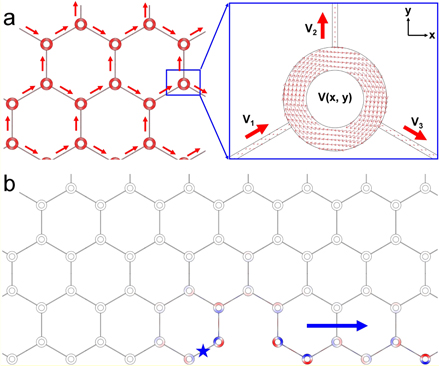
Figure E1. The robust one-way edge modes tolerant of the inter-cell flows in the waveguides and the inhomogeneous flow in the rings. (a) The air-flow distribution of the topological sonic crystal system. The speed of air flow inside the rings is inhomogeneous, while that inside the waveguides is homogeneous. The red arrows represent the amplitude and direction of the air flow. (b) The velocity–potential distribution of a one-way edge mode robust to a void defect. The blue star shows the location of the acoustic source with frequency of 770 Hz, and the blue arrow gives the propagating direction of the edge mode. Color from red to blue represents the value from maximum to minimum.
Download figure:
Standard image High-resolution imageAs to the details of simulation, we utilize the aeroacoustics module of COMSOL Multiphysics, which is a finite-element-method based commercial simulation software. This aeroacoustics module is based on solving the equation below

where  is the velocity potential,
  is the angular frequency of sound,
  is the density of air,
  is the sound speed of air, and
  is the speed of air flow. In the simulation (figure E1(a)), we set the air-flow speed inside the
  th ring to be
  where
where  is the maximum amplitude,
  is the minimum amplitude,
  is the ring's outer radius, and
  is the location of the center of the
  th ring. The speed of air flow inside the waveguides are

 with the amplitudes
  The resulted field distribution (figure E1(b)) still shows a robust one-way edge mode propagating to the right side with the acoustic source (770 Hz) located at the blue-star position. This simulation result suggests that the one-way edge mode is highly robust to both the inhomogeneous air flow inside the rings and the inter-cell flows in the waveguides.
Appendix F: The higher-frequency bands corresponding to the ring's azimuthal mode of m = 2
Figure F1. The bulk frequency bands of the sonic crystal without air flow (V = 0, denoted by red circles) and with clockwise air flow (V = 10 m s−1, denoted by black squares) in a higher frequency range corresponding to the ring's azimuthal mode of m = 2. (b) The projected frequency bands of the sonic crystal with clockwise air flow (V = 10 m s−1) along x direction (zigzag edge) in a higher frequency range.
Download figure:
Standard image High-resolution image