


Abstract
The physical properties of interfaces between organic semiconductors and metal surfaces crucially influence the performance of organic electronic devices. In order to enable the tailoring of such metal–organic hybrid interfaces we study the adsorption of heteromolecular thin films containing the prototypical molecules copper-II-phthalocyanine (CuPc) and 3,4,9,10-perylene-tetra-carboxylic-dianhydride (PTCDA) on the Ag(111) surface. Here, we demonstrate how the lateral order can be tuned by changing the relative coverage of both adsorbates on the surface. The layer growth has been studied in real time with low energy electron microscopy, and—for different stoichiometries—the geometric properties of three heteromolecular submonolayer phases have been investigated using high resolution low energy electron diffraction and low temperature scanning tunneling microscopy. Furthermore, we have used a theoretical approach based on van der Waals and electrostatic potentials in order to reveal the influence of the intermolecular and the molecule–substrate interactions on the lateral order of heteromolecular films.
Export citation and abstract BibTeX RIS

Content from this work may be used under the terms of the Creative Commons Attribution 3.0 licence. Any further distribution of this work must maintain attribution to the author(s) and the title of the work, journal citation and DOI.
1. Introduction
One crucial issue for the success of organic materials in electronic devices is the ability to specifically design the interfaces between different active layers according to their functional purpose. In particular, the contact between metal and functional organic molecules is of great importance for device performance. This is, on the one hand, due to charge carriers, which have to cross this interface when they are injected into the active organic film. On the other hand, the first organic layer, which is in direct contact with the metal substrate, acts as a template for the subsequent growth during fabrication of the thin film and has great influence on its structural properties. The latter are of particular importance for the performance of any organic-based device. In order to control these properties, the complex interplay between intermolecular and molecule–substrate interaction and their consequences for the geometric and electronic structure at metal–organic interfaces have to be understood.
For that reason, the adsorption of different prototype molecules on  -oriented noble metal surfaces has been investigated over the last decades [1–9]. These particular surfaces are highly interesting since the interaction between the adsorbed molecules and the substrate is of similar importance as intermolecular interactions. Consequently, the fine interplay of these two types of interactions plays a decisive role, and often only subtle details determine the properties of the films. This leads to unexpected effects and complex structural phase diagrams for these metal–organic interfaces [10–17]. One example is the chemical bonding between metal-phthalocyanine (MePc) molecules and the Ag(111) substrate, which results in a (substrate mediated) repulsion between the molecules [10, 13, 18]. This effect leads not only to a 2D-gas like growth of the molecules for submonolayer coverages, but—at rising coverage—also to a continuously shrinking unit cell for ordered structures phase. The situation is different for molecules like 3,4,9,10-perylene-tetra-carboxylic-dianhydride (PTCDA) [19–21] or 1,4,5,8-naphthalene-tetra-carboxylic-dianhydride (NTCDA) [14, 22–24], which exhibit a permanent electrostatic quadrupole moment. The attractive interaction between the molecules, which in some cases is enhanced by charge transfer from the surface, results in the formation of ordered molecular islands even for very low submonolayer coverages. Increasing the number of molecules on the surface enlarges the size of the islands without changing their internal structure. However, although in principle the molecule-molecule interaction is responsible for the formation of islands, the precise local arrangement of the molecules within these islands is in many cases driven by the molecule–substrate interaction. Especially in the case of chemical bonding between molecules and surface, an alignment of molecules along high-symmetry directions of the substrate, for example, along rows of substrate atoms, is likely in order to maximize the overlap between electronic states of the molecule and of the substrate.
The fundamental mechanisms that are responsible for the interface formation of homomolecular layers on the metal surface are well understood, and details are often determined by intrinsic properties of the interface components and can hence only be modified by substituting either the surface material or the molecular adsorbate. This situation becomes even more complicated when heteromolecular monolayer films consisting of two different types of molecules are considered due to an additional parameter, the ratio of coverages. But for the same reason, these layers offer great potential for selectively tuning the shape and size of the adsorbate lattice on a particular surface by changing the relative ratio of the adsorbates on the substrate [25, 26]. This would allow us to tailor metal–organic interfaces and hence to control the subsequent film growth as well as the electron injection barrier.
On the way towards realization of such tailor-made systems, the first studies on the lateral order in heteromolecular adsorbate films have been reported recently [25–28]. They already demonstrated that the lateral periodicity can indeed be influenced by the stoichiometry of the components and that the arrangement of the molecules in the heteromolecular films is mainly determined by intermolecular interactions. In addition to these findings, however, we recently revealed the importance of the molecule–substrate interaction for the properties of heteromolecular-metal hybrid interfaces formed by coadsorption of copper-II-phthalocyanine (CuPc) and PTCDA on Ag(111) [29]. The differences in the charge affinity of the molecules lead to charge transfer from CuPc to PTCDA via the Ag(111) substrate and has consequences for both the electronic and geometric structure of the interface. While we focused on the electronic properties in [29], in particular on the origin of the substrate-mediated charge transfer, we concentrate on the lateral structure formation and the growth modes of the lateral monolayer films in the present paper. A combination of several experimental techniques allows us to determine the structures of three ordered phases with different CuPc/PTCDA stoichiometry in the (sub-) monolayer coverage regime. While low energy electron microscopy (LEEM) is used to study the formation of the heteromolecular films in real time, we apply spot profile analysis low energy electron diffraction (SPA-LEED) and low temperature scanning tunneling microscopy (LT-STM) to determine the lateral order of these films with highest precision. The structural parameters found in the experiments are verified by pair-potential calculations, which reveal the influence of the molecule substrate and of the intermolecular interactions on the structure formation in heteromolecular films.
2. Experimental details
2.1. Sample preparation
All experiments and sample preparations were carried out under ultra-high vacuum conditions with a base pressure better than  mbar. The surface of the Ag(111) single crystal was cleaned by repeated cycles of Ar ion bombardment
  incident angle of the ion beam,
  min,
min,  ) and subsequent annealing with temperatures of
  K for
K for  minutes. Evaluating the transfer width of the specular reflection obtained with the SPA-LEED instrument revealed that such preparation delivers large Ag(111) terraces (
 Å).
Å).
The organic layers were prepared by organic molecular beam deposition (OMBD) using a dedicated evaporator. Except for one of our real-time LEEM studies, the sample was kept at room temperature for the preparation of the organic films. The CuPc and PTCDA molecules were deposited sequentially onto the Ag(111) surface. In the SPA-LEED chamber, the molecular flux was monitored during the growth process by measuring molecular fragments with a quadrupole mass spectrometer ( au for CuPc and
  au for PTCDA). We used constant deposition rates of
  . The coverage of both molecular species in the heteromolecular films was determined separately for both individual deposition steps by the integrated QMS signal, which was normalized to the one of the corresponding homomolecular monolayer film. The latter is defined as that organic overlayer with the highest (homo)molecular surface density completely covering the silver surface. Therefore, all molecular coverages
  and
and  given in this paper represent the amount of CuPc and PTCDA molecules present on the silver surface relative to homomolecular closed layers, and hence do not refer to the molecular surface density of the different heteromolecular structures.
2.2. Low energy electron microscopy
The LEEM experiments were performed using a commercial Elmitec AC-SPE-LEEM III. During the growth processes, LEEM images were recorded continuously with an acquisition time of  s per video frame. All data were recorded in bright field mode in which mainly the specular reflection contributes to the contrast of the real space image. We used a start voltage of
  V and a field of view of
  . During and after the measurements, no indications for radiation damage have been detected.
2.3. High resolution low energy electron diffraction
The LEED data were obtained using a SPA-LEED instrument (Omicron). This device operates with very low electron flux ( nA) which allows a non-destructive investigation of organic samples. In order to achieve the highest accuracy, we exclusively recorded the diffraction pattern in the k-space segment, which reveals the smallest distortion of the reciprocal space pattern. These distortions are due to extreme trajectories of the diffracted electrons in the inhomogeneous field of the SPA-LEED instrument and are a well-known artifact of SPA-LEED systems. In order to determine the structural lattice parameters, the recorded diffraction patterns were calibrated using the SPA-LEED pattern of the PTCDA monolayer structure (herringbone phase) on Ag(111). The epitaxial matrix can be determined with an accuracy of ±0.04 for each matrix entry. This error is propagated to the lattice parameters.
2.4. Scanning tunneling microscopy
All STM experiments were carried out at low temperature ( K) using a commercial Createc LT-STM. STM images were recorded in constant current mode. Since the unit cell dimensions were precisely known from the SPA-LEED measurements, we could correct all images for distortions.
3. Experimental results and discussion
A schematic overview of different CuPc-PTCDA heteromolecular phases on the Ag(111) surface is shown in figure 1. Except for very low molecular coverages below  ML, long-range ordered mixed structures are formed, which can be classified according to their stoichiometry. The total coverage for all these molecular blends is less than or equal to one organic layer, and the total thicknesses is
  Å as revealed recently by the normal incidence x-ray standing wave technique [29, 30]. For CuPc coverages (
 ) smaller than
  ML and PTCDA coverages (
 ) larger than
  ML, the Mixed Brick Wall (MBW) structure is observed
1
. This structure is characterized by a commensurate registry with the silver surface and contains two PTCDA and one CuPc molecule per unit cell. The surface density of PTCDA and CuPc in the MBW, as well as in all other heteromolecular structures on Ag(111), is comparable to the one of the individual molecular species in their homomolecular monolayer structure. Typically, the MBW structure coexists with islands of the homomolecular PTCDA/Ag(111) monolayer structure, which take up the excessive PTCDA molecules.
ML, the Mixed Brick Wall (MBW) structure is observed
1
. This structure is characterized by a commensurate registry with the silver surface and contains two PTCDA and one CuPc molecule per unit cell. The surface density of PTCDA and CuPc in the MBW, as well as in all other heteromolecular structures on Ag(111), is comparable to the one of the individual molecular species in their homomolecular monolayer structure. Typically, the MBW structure coexists with islands of the homomolecular PTCDA/Ag(111) monolayer structure, which take up the excessive PTCDA molecules.

Figure 1. Schematic overview of the three different heteromolecular phases observed for different coverages of CuPc and PTCDA on Ag(111). The SPA-LEED patterns show typical diffraction signatures ( eV), the insets show either STM images (MBW and M121,
  ) or a structural model (MZZ).
Download figure:
Standard image High-resolution imageWhen increasing the CuPc coverage up to  ML and using PTCDA coverages below
  ML, the Mixed One-to-One (M121) phase is formed. It is found in two structures, one is commensurate and the other shows a point-on-line coincidence with the substrate, but both have an almost squared unit cell containing one molecule of each type. Finally for CuPc coverages larger than
  ML and PTCDA coverages below
  ML, the Mixed Zig-Zag (MZZ) phase is visible. In this regime, different structures with large unit cells containing two CuPc and one PTCDA molecules are found. Note that all organic blends do not undergo any lattice parameter changes upon cooling to cryogenic temperatures, as proven by SPA-LEED. The relative number of molecules found in the mixed structures approximately reflects the coverage of molecules deposited on the surface. This finding indicates that the lateral order in heteromolecular structure can indeed be tuned by changing the relative molecular coverage.
Before we report on more structural details of these three heteromolecular phases, we first discuss the layer formation of CuPc-PTCDA mixed films based on a real-time LEEM study in the following section. In addition, we report pair potential calculations in order to achieve a better understanding of the intermolecular interaction between CuPc and PTCDA and to reveal the influence of this interaction—in relation to molecule–substrate interaction—on the lateral order of heteromolecular CuPc-PTCDA films.
3.1. Investigation of the growth
All three thermodynamically stable heteromolecular structures can be prepared either by deposition of PTCDA onto a submonolayer CuPc/Ag(111) film or by the reversed deposition sequence. For both cases, the transformation from the homomolecular to the heteromolecular film can be monitored in real time by LEEM. We have exemplarily chosen the formation of the MBW structure in order to demonstrate qualitative differences between both deposition sequences.
Figure 2(a) shows snapshots recorded during the deposition of PTCDA on a submonolayer film of  ML CuPc/Ag(111) at room temperature. The homomolecular CuPc film (first image of panel a) reveals an homogeneous contrast with very low intensity, which is due to the 2D lattice gas of CuPc. At the specific electron energy selected for this experiment, the intensity is small because of destructive interference between electrons reflected at the molecular layer and at the bare silver surface. This effect is similar to intensity modulations observed in reflection high-energy electron diffraction (RHEED) during thin film growth. The deposition of PTCDA immediately results in the formation of areas with a brighter contrast (second image), which can be identified by LEED as islands of the MBW structure. The size of these MBW islands increases with rising PTCDA coverage (third image) until the deposition is stopped (fourth image) or all CuPc molecules are incorporated in the MBW islands. A movie showing the entire deposition process is available as supplementary online material.
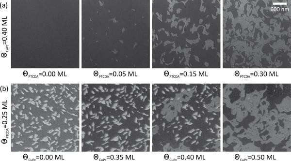
Figure 2. Bright-field LEEM images taken during the deposition of the second molecular component ( V). Row (a): deposition of PTCDA on a submonolayer film of CuPc on Ag(111) at room temperature: MBW islands (bright contrast) appear immediately when the deposition of PTCDA is started. Their size increases linearly with the PTCDA coverage. Row (b): deposition of CuPc on a submonolayer film of PTCDA on Ag(111) at
  K: initially (second image) CuPc forms a 2D lattice gas between the existing PTCDA islands (bright contrast), which are essentially unchanged. Only after the lattice gas has reached a sufficiently high density, MBW islands are formed (third image, islands having the same contrast as those in row (a)) and grow until all PTCDA islands have disappeared. All images are taken from LEEM movies showing the entire deposition process. These movies are available as supplementary online material (available at stacks.iop.org/njp/17/023046/mmedia).
Download figure:
Standard image High-resolution imageThe finding that MBW islands are formed indicates that the intermolecular interaction between adsorbed CuPc and PTCDA is, in general, attractive. Due to the high mobility of CuPc at this temperature, the thermodynamically most stable structure is formed immediately. Changing the deposition sequence, that is first PTCDA, then CuPc, results in no direct mixing of CuPc and PTCDA at room temperature (without any further annealing). Instead, both homomolecular phases coexist in separate areas on the same terrace. In this case, the formation of a mixed structure can be achieved either by annealing the sample at K, or by performing the second deposition at an elevated temperature of
 K. For the latter case, exemplary snapshots of our LEEM study recorded during CuPc deposition are shown in figure 2(b); the full movie is again available as supplementary material. The first image reveals the LEEM contrast of a PTCDA submonolayer film. The areas with bright contrast can be identified as molecular islands; the ones with dark contrast as bare substrate. When starting the deposition of CuPc, the LEEM intensity from the bare substrate decreases significantly. This indicates that CuPc forms a 2D gas phase in the regions between the PTCDA islands and confirms that a phase separation of the homomolecular phases of CuPc and PTCDA exists at this stage. As the CuPc coverage increases, the PTCDA islands start to dissolve, and islands of the first mixed structure (MBW) appear (third image). The MBW islands continue growing until all PTCDA islands have disappeared (fourth image).
For this deposition sequence, a thermal activation barrier has to be overcome before a mixed structure is formed. This is the result of an intermolecular attraction between the PTCDA molecules in their homomolecular herringbone structure and a low detachment rate of PTCDA from the islands at room temperature. Since CuPc cannot penetrate the PTCDA islands, those are stable and surrounded by the CuPc 2D gas. At elevated sample temperatures, the detachment rate of the PTCDA molecules increases and their high mobility allows diffusion into the CuPc 2D gas regions. We also observe that CuPc is now penetrating into the PTCDA islands. Both processes contribute to the formation of the heteromolecular structure since we observe both the formation of new MBW islands in the CuPc 2D gas regions and the conversion of PTCDA islands to the MBW structure.
The thermally activated mixing also indicates that the mixed layer is the thermodynamic equilibrium state and hence energetically more favorable than two separated homomolecular CuPc and PTCDA phases. A more detailed and quantitative analysis [31] of the LEEM results, including studies of the growth of the other phases, are beyond the scope of this paper and will be published subsequently.
3.2. Modeling intermolecular interactions by pair potential calculations
As discussed in the previous section, the formation of heteromolecular films reveals clear signs of an attractive interaction between CuPc and PTCDA. We now want to understand this finding by discussing the interaction between individual CuPc and PTCDA molecules in the framework of a pair potential approach [32, 33]. In this theoretical approach, the interaction energy between two molecules A and B is calculated by the sum over two-body potentials of every atom of molecule A with every atom of molecule B. The two-body potentials consider van der Waals and electrostatic contributions, for which we use a set of parameters that has been proven to describe the intermolecular interactions of homomolecular combinations of PTCDA and CuPc molecules very accurately [32]. The structural parameters, which were varied in these calculations, are the lateral distance vector  between the centers of the two molecules and their relative orientation
  . In practice, we have fixed the CuPc molecule at a certain position and in a certain orientation (in the center of the maps shown in figures 3 (a)–(e) and with its long axes horizontally and vertically), and scan the PTCDA molecule across the relevant area. Within one map, the PTCDA molecule is also kept in a fixed orientation, whereby
  is the angle between its long axis and the
  -direction. Other rotations around the x- and y-axes (
 and
and  ), as well as the vertical displacement
  between the two molecules, were always kept at zero. This corresponds to the assumption of a flat adsorption geometry for both molecules at the same height above the surface (although, the interaction with the surface was not considered). We furthermore treated the molecules as rigid objects with an inner geometry that was optimized beforehand by density functional theory for free molecules in the gas phase. More technical details about this method can be found elsewhere [32].

Figure 3. (a)–(e) Pair potential maps for different orientations  of the PTCDA molecule. The CuPc molecule is always oriented horizontally with its long symmetry axis.
  is the distance vector between the molecules. Red areas indicate regions of intermolecular repulsion, and green/blue areas indicate attraction. Panel (f) shows radial line profiles through minima in the maps as they are indicated by dashed lines in (a)–(e).
Download figure:
Standard image High-resolution imageIn figure 3 the results of pair potential maps for five different orientations  are shown. Each point of the map represents the pair potential energy as a function of the distance vector
  and the relative orientation
  . The color code illustrates the energies of the pair potential calculations, with positive energies depicted in red and negative energies in green and blue. All maps reveal that the interaction between CuPc and PTCDA is dominated by an attractive intermolecular interaction (large areas with negative potential values in the maps figures 3(a)–(e) and negative values in the line profiles figure 3(f)). This is caused by an electrostatic attraction between the negatively charged oxygen atoms of the PTCDA molecule and the positive partial charge on the hydrogen atoms of CuPc, and by van der Waals forces. There are also regions with a repulsion between the molecules, but these cover smaller areas in the potential maps. They arise from the electrostatic repulsion between the positively charged hydrogen atoms on both molecules. But overall, the interaction between CuPc and PTCDA can be described as mostly attractive.
Note that there are sharp and distinct potential minima for all relative orientations. Radial line profiles through the prominent minima for different relative orientations  are shown in figure 3(f). The energy gain in these potential minima is much larger than the thermal activation energy at room temperature. Therefore, PTCDA molecules can be trapped in the vicinity of CuPc, which leads to the formation of a mixed structure. The largest energy gain of
  meV was found for
  and
and  . This value has to be compared with corresponding numbers calculated for CuPc-CuPc and PTCDA-PTCDA pair potentials. In [32] we found
  meV for the first and
  meV for the latter. From this simplified energetic approach based on the interaction of pairs of molecules and neglecting entropy effects, the formation of the mixed film appears questionable since the value for the mixed molecular system lies between the corresponding values for the homomolecular systems. But note that in the CuPc-CuPc case, the minima are very strongly localized while the interaction otherwise is dominantly repulsive [32, 34]. In particular, when PTCDA is deposited on a diluted gas-phase of CuPc/Ag(111), that is, when the CuPc molecules have rather large distances to their neighbors, which is energetically an unfavorable situation since it is in the repulsive regime of the CuPc-CuPc pair potential map, the PTCDA molecules can rather easily squeeze themselves in between the CuPc molecules. It is then plausible that the CuPc-PTCDA pairs find their optimum relative position in the mixed phase.
Hence, when forming a blend with PTCDA, the CuPc molecules can transform the intermolecular repulsion between each other into an attractive interaction with PTCDA. This results in an energy gain for the entire system, which is even enhanced when considering substrate-mediated intermolecular exchanges reported earlier for this heteromolecular adsorbate system [29]. Furthermore, the entropy term, which was neglected in the discussion so far, will obviously always favor the formation of mixed structures rather than a phase separation.
In the case of reversed deposition, when PTCDA has to be dissolved from compact islands, the formation of the blend is a question of thermal energy (and also the CuPc density). PTCDA molecules at the edges of the PTCDA homomolecular islands, which are stably bonded to their neighbors, must be detached from that island in order to be able to form large mixed islands, and since the PTCDA-PTCDA pair is more stable than a CuPc-PTCDA pair, this is not possible without thermal activation.
We finally would like to note that the optimum relative position between CuPc and PTCDA is reflected only by the minimum in the map for  , although the minimum for
  is almost equally deep. The reason is that the optimized distance between CuPc and PTCDA is smaller for the
  -minimum, so that in this orientation a higher packing density and therefore a larger energy gain per surface area can be achieved. Hence, for a close-packed structure, our pair potential calculations suggest a relative orientation of
  between CuPc and PTCDA. As we will demonstrate later, this value is close to our experimental finding for all heteromolecular films.
3.3. The Mixed Brick Wall structure
We now turn to a more detailed discussion of the individual heteromolecular structures. The Mixed Brick Wall structure is found for coverages  ML and
  ML, that is, in the PTCDA-rich regime. A typical LEED pattern of this commensurate structure with two PTCDA molecules and one CuPc molecule is shown in figure 4(a). In the lower-left part, the calculated diffraction spot positions of the superstructure matrix

are indicated by blue circles. The corresponding unit cell vectors have a length of  Å and
Å and  Å with an angle of
  . Additional diffraction spots, which cannot be explained by this superstructure matrix, stem from the PTCDA monolayer structure [19]. Obviously, excessive PTCDA molecules form homomolecular islands, while practically all CuPc molecules are included in the mixed islands. This indicates that mixed structures with more than two PTCDA molecules per unit cell are not favored on Ag(111).
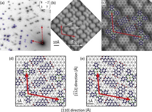
Figure 4. Structural details of the MBW structure. (a) SPA-LEED image recorded at  eV. Blue circles in the lower-left half of the diffraction image indicate calculated spot positions. All spots in this part of the image that are not described by blue circles stem from parasitic islands of the homomolecular PTCDA herringbone structure. (b) and (c) High resolution STM images (
 Å
Å Å and
Å and  Å
Å Å, respectively,
  V,
V,  nA). In (c) the unit cell is indicated by red arrows and ball-and-stick models of the molecules are shown, indicating their position relative to the substrate lattice (black grid). (d) and (e) show hypothetic structures which were found by minimizing the pair potential energy for a free-standing heteromolecular film with the given stochiometry and unit cell size. Structure (d) is very similar to the existing MBW structure, but structure (e) was not found in the experiment.
Download figure:
Standard image High-resolution imageThe island growth, as well as the formation of a commensurate structure for a large coverage regime, are properties that the MBW structure has in common with the homomolecular PTCDA monolayer film. This suggests that the structure formation of the mixed film is dominated by the adsorption behavior of the PTCDA molecule. In particular, the site-specific interaction of the carboxylic oxygen atoms with the underlying silver should be present in the mixed structure [2, 35].
Combining the diffraction results with a local probe technique allows a complete characterization of the unit cell. In the STM image shown in figure 4(b) the molecular species in the unit cell can be distinguished easily. While CuPc shows its typical cross-like shape, the PTCDA molecules feature an elongated form. A qualitative analysis reveals that the PTCDA molecules in the MBW structure are not arranged in a herringbone pattern like in the PTCDA monolayer [21], but are aligned parallel to each other and form alternating rows with the CuPc molecules. Since the orientation of the mixed structure unit cell with respect to the silver substrate grid is known from the diffraction measurement, the orientation of the molecules in the unit cell can be analyzed quantitatively. We find that one pair of CuPc wings is almost aligned with the ![$[\bar{1}10]$](https://content.cld.iop.org/journals/1367-2630/17/2/023046/revision1/njp508556ieqn70.gif) -direction of the substrate (
-direction of the substrate (![${{\theta }_{{\rm CuPc},[\bar{1}10]}}={{(4\pm 5)}^{\circ }}$](https://content.cld.iop.org/journals/1367-2630/17/2/023046/revision1/njp508556ieqn71.gif) ), whereas both PTCDA molecules are rotated by almost 30° with respect to this direction (
), whereas both PTCDA molecules are rotated by almost 30° with respect to this direction (![${{\theta }_{{\rm PTCDA},[\bar{1}10]}}={{(27\pm 5)}^{\circ }}$](https://content.cld.iop.org/journals/1367-2630/17/2/023046/revision1/njp508556ieqn72.gif) ). In figure 4(c), the substrate grid is superimposed on the structural model of the MBW phase (in an arbitrary position since the adsorption sites are not known), which indicates that the molecules are located on identical adsorption sites, and therefore are equivalent in their adsorption geometry. However, they are not aligned along a prominent substrate direction, which inhibits the formation of Ag–O bonds for some of the carboxylic oxygen atoms since not all of them can be located directly on top of silver atoms.
). In figure 4(c), the substrate grid is superimposed on the structural model of the MBW phase (in an arbitrary position since the adsorption sites are not known), which indicates that the molecules are located on identical adsorption sites, and therefore are equivalent in their adsorption geometry. However, they are not aligned along a prominent substrate direction, which inhibits the formation of Ag–O bonds for some of the carboxylic oxygen atoms since not all of them can be located directly on top of silver atoms.
Although the PTCDA molecule is supposed to be the prominent species in the MBW structure formation, its alignment with the substrate as well as with its neighboring PTCDA molecules differs from the homomolecular monolayer structure. However, the formation of a brick wall arrangement of PTCDA molecules in the blend cannot be explained only by direct intermolecular interactions with CuPc alone, as we will show in the following: we have performed pair potential calculations also for this system and optimized the lateral position vectors  and the rotation angles
  of all three molecules in the unit cell. For these calculations, we placed CuPc molecules at the corners of the MBW unit cell, and two PTCDA molecules at variable positions in the cell. Using a structural optimization algorithm, the positions and orientations of the PTCDA molecules, as well as the orientation of the CuPc molecules, were then allowed to relax towards a potential minimum, whereby we always ensured that enough neighboring molecules are taken into account. We repeated this relaxation with many different start values for positions and orientations in order not to miss any relevant minimum in the potential landscape
2
.
of all three molecules in the unit cell. For these calculations, we placed CuPc molecules at the corners of the MBW unit cell, and two PTCDA molecules at variable positions in the cell. Using a structural optimization algorithm, the positions and orientations of the PTCDA molecules, as well as the orientation of the CuPc molecules, were then allowed to relax towards a potential minimum, whereby we always ensured that enough neighboring molecules are taken into account. We repeated this relaxation with many different start values for positions and orientations in order not to miss any relevant minimum in the potential landscape
2
.
These calculations yielded two geometries which correspond to two distinct potential minima. Ball-and-stick models of these two geometries are shown in figures 4(d) and (e). Note that the first model, which corresponds to the less deep minimum of the two, is very similar to the MBW structure found in the experiment (compare figures 4(c) and (d)). While the orientations of all molecules fit exactly, the lateral position of the PTCDA molecules differ slightly (by 0.7 Å). Such a small difference is not surprising when considering the fundamental simplifications in our model and can easily be caused by the neglect of molecule–substrate interactions. However, from these calculations it is obvious that this structure is stabilized by the electrostatic attraction between positively charged hydrogens on PTCDA and CuPc, and negatively charged oxygens on PTCDA. The distance between these atom pairs is  Å, close to the expected distances for hydrogen bonds [36]. But it also has to be mentioned that the relative position of both PTCDA molecules implies a relatively strong repulsion between them, since the hydrogen-groups are facing each other (see figure 4a of [32]). This reduces the energy that can be gained by forming this structure.
The second minimum found by this kind of calculations is almost four times deeper and corresponds to a mixed structure with the PTCDA molecules in a herringbone arrangement; see figure 4(e). However, such a structure was not found in the experiment. This suggests that the brick wall orientation of the PTCDA molecules in the MBW structure is caused by the interaction with the substrate, which is not included in our calculations. It has been shown in [29] that the electronic interaction between molecules and the Ag(111) surface in the MBW structure is very important. It even causes a complete depletion of charge from the former lowest occupied molecular orbital (F-LUMO) of CuPc, while the PTCDA F-LUMO becomes (almost) completely filled. However, this kind of interaction and the consequences for the structure formation depend strongly on the specific choice of substrate and adsorbate. This becomes clear when the adsorption of the same molecules on a copper (111) surface is considered: for that system a phase was reported [27], which is very similar to the hypothetic mixed herringbone structure suggested by our calculations (figure 4(e)), with very little differences in the molecular arrangements. In contrast to the Ag(111) surface, the herringbone—not the brick wall—arrangement was found experimentally for Cu(111), which is the one being energetically more stable when surface interactions are neglected. This finding emphasizes the crucial role of the substrate for the structural properties in the heteromolecular films. In our case the interactions with the surface are obviously more important on Ag(111) than on Cu(111).
3.4. The Mixed One-to-One Phase
Upon increasing the CuPc coverage up to  ML, while keeping that of PTCDA below
  ML, the Mixed One-to-One (M121) phase is formed. In this coverage regime, two main mixed structures with almost square unit cells are observed. Their diffraction patterns are displayed in figures 5(a) and (b). From the corresponding superstructure matrices it is evident that within the experimental error, one of these structures can be classified as truly commensurate, whereas the other structure is only uniaxially commensurate. Its lattice vector b has almost integer coordinates, but a is only point-on-line, and therefore we entitle this structure 'p.o.l. M121' in the following. Annealing at
  K for
K for  min transforms the p.o.l. M121 structure into the commensurate M121 structure, whereby at least one intermediate structure has been observed. This goes along with an expansion of the lattice, since the unit cell area of the p.o.l. structure is slightly smaller than the one of the commensurate structure (
 Å
Å Å
Å ). The behavior is hence very similar to that of the bare CuPc/Ag(111). The latter system exhibits a continuous expansion of the unit cell upon reducing the coverage from 1.0 ML to 0.9 ML (e.g., by annealing), which is a clear indication for the repulsive intermolecular interaction of CuPc molecules [10].
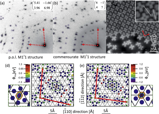
Figure 5. Different structures in the regime of the Mixed One-to-One phase: the point-on-line structure (a) can be transformed to a commensurate structure (b) by annealing. (c) LT-STM data ( V,
V,  nA) for the commensurate M121 structure (upper part). The inset is zoomed by a factor of 2, and dashed white lines indicate the molecular orientation. Note that the island is decorated with CuPc molecules at its edges and surrounded by a (frozen) CuPc lattice gas. (d) and (e) Ball-and-stick models of both structures, obtained from pair potential grid calculations for the given stoichiometry and unit cell sizes. The unit cell is indicated by red arrows. In the calculations, the PTCDA position can only be varied in a very small region due to steric conditions. A close-up of this region located close to the center of the unit cell is shown in the insets.
Download figure:
Standard image High-resolution imageMore local information on the molecular assembly of the commensurate M121 structure is provided by LT-STM. Interestingly, this mixed structure is often found in islands on terraces that otherwise are covered with disordered CuPc molecules. We also observed that the entire edges of the mixed islands are decorated by CuPc molecules, as can be seen in figure 5(c). This is obviously the result of the attractive interaction between CuPc and PTCDA: whenever an island of the mixed phase is terminated by PTCDA, a CuPc molecule will be attracted from the surrounding 2D gas and attach to the island.
The molecular arrangement within these islands is very similar to the MBW structure, but with only one PTCDA molecule in the unit cell. In figure 5(c), the dotted white lines indicate the relative orientation of the molecules. It turns out that the CuPc molecules are, with respect to the substrate, identically oriented as in the MBW structure, and that the angle between the long axis of PTCDA and one pair of wings of the CuPc molecule is 30°, very similar to the MBW-film. It should be noted that the CuPc molecules decorating the island edge in figure 5(c), as well as the molecules in the disordered frozen 2D gas phase, exhibit a brighter electronic contrast than the CuPc molecules within the island (at the tunneling conditions chosen for this image). This is consistent with a modified electronic structure of the molecules in the heteromolecular CuPc/PTCDA films on Ag(111), which was reported recently [29].
Also for this phase the structural parameters can be understood in the framework of the pair potential approach [32]. We have optimized the molecular arrangement, including the interaction with eight direct neighbors. The unit cell parameters known from LEED are again considered in the calculation. The CuPc molecules are fixed at the corners of the unit cell and the distance vector  of PTCDA as well as both rotational angles
  are varied when calculating pair potential maps. The geometries corresponding to minimum energy are displayed in figures 5(d) and (e) together with the potential energy maps.
Due to steric conditions, the region for possible PTCDA positions is very small. It is located in the middle of the unit cell and highlighted in the inset. Since both lattices are quite similar, the resulting geometries are also almost identical. The PTCDA rotation with respect to the substrate is 30° for the commensurate structure and 40° in the p.o.l. lattice. This agrees very well with the structural model derived from STM data for the commensurate M121 structure. These values are also close to the results of our pair-potential calculation obtained for individual pairs of CuPc and PTCDA molecules, which were discussed earlier in this article.
Comparing the pair potential energy of both structures reveals a slightly deeper energy minimum for the mixed p.o.l. structure. This suggests that this structure represents the stable ground state, which is not in agreement with the experimental finding since the p.o.l. M121 structure can be transformed into the commensurate structure by annealing. It is plausible that the reason for this discrepancy is again the interaction with the substrate, which is certainly stronger for the commensurate structure, but not considered in our pair potential approach.
3.5. The Mixed Zig-Zag phase
The Mixed Zig-Zag (MZZ) phase was found for coverages  ML and
  ML, that is, in the CuPc-rich regime. In this regime, a variety of incommensurate structures with roughly the same unit cell size of
  Å2 can be obtained. This value and the deposited amount of both molecules suggest a mixing ratio of two CuPc and one PTCDA per unit cell. A detailed analysis of the LEED data indicates that the unit cell size decreases slightly with increasing CuPc coverage. In figure 6(a) the LEED pattern of the lattice with the smallest unit cell size of all MZZ structures is shown together with calculated diffraction spots in parts of the image. All additional spots that are not explained by the simulation are caused by multiple scattering of the electrons by the silver crystal and the organic film. Electrons diffracted twice, once by the bulk and once by the organic layer, reproduce the diffraction pattern of the organic film—which is usually located only at the (00) reflection—also around all (hk) reflections of the Ag crystal. This phenomena is observed for all incommensurate lattices in this phase. Note that the multiple electron scattering effect results in additional diffraction maxima only for incommensurate structures. For commensurate superstructures, which were discussed earlier, the diffraction peak positions of multiple and single scattered electrons coincide.

Figure 6. Structures in the regime of the MZZ phase: (a)–(c) SPA-LEED images of structures with the smallest (a) and largest (b) unit cell. The commensurate structure (c) can only be observed when PTCDA is deposited on a submonolayer film of CuPc without sample annealing. (d) Unit cells of all MZZ structures drawn on the Ag(111) surface lattice. (e) Structural model of the commensurate MZZ structure as revealed from pair potential calculation.
Download figure:
Standard image High-resolution image
The diffraction pattern of the smallest MZZ-structure (see figure 6(a)) can be modified by annealing at  K for 20 min. Repeating this annealing procedure several times and monitoring the diffraction pattern after each annealing step reveals a continuous expansion of the mixed structure unit cell. The LEED image of the MZZ-structure with the largest unit cells of the mixed structures is shown in figure 6(b). The evolution of the adsorbate lattice is illustrated by plotting the unit cell vectors on the Ag(111) grid in figure 6(d). The heads of the unit cell vectors move on straight lines towards grid points of the silver lattice. This behavior indicates a line-on-line (l.o.l.) coincidence between the structures of the MZZ phase and the silver substrate [37], and reveals a transformation of these l.o.l. structures into a commensurate structure. Although the predicted commensurate structure could never be prepared by annealing the l.o.l. structures, not even after very long sample annealing, it can be produced by depositing the correct amount of PTCDA on a CuPc-covered surface. The corresponding LEED pattern is shown in figure 6(c).
Figure 6(e) shows our suggestion for a model of the commensurate MZZ structure. The positions of the molecules, as well as their rotation angles, are obtained from pair potential calculations as described previously for the MBW structure. In the optimized structure, both CuPc molecules are slightly tilted ( ,
,  ) with respect to the
 ![$[\bar{1}10]$](https://content.cld.iop.org/journals/1367-2630/17/2/023046/revision1/njp508556ieqn93.gif) -direction of the substrate. This causes the formation of CuPc zig-zag chains, which are separated by PTCDA molecules. The orientation angle of the PTCDA molecule is
-direction of the substrate. This causes the formation of CuPc zig-zag chains, which are separated by PTCDA molecules. The orientation angle of the PTCDA molecule is  . Consequently, the angle between CuPc and PTCDA is
  and hence very similar to the value found for all other heteromolecular phases on Ag(111). This agreement provides evidence for the reliability of the presented model, even though no STM data are available.
Repeating the pair potential calculation for all l.o.l. MZZ structures reveals that the depth of the relevant energy minimum increases with increasing unit cell size. For the densest molecular packing, even a positive pair potential energy was found, suggesting that this structure is not stable. However, since this structure was observed experimentally, it must be stabilized by the molecule–substrate or by a substrate-mediated intermolecular interaction, which are not considered in our theoretical approach.
The calculations explain the structural relaxation upon annealing, at least qualitatively. Annealing causes desorption of CuPc molecules from the surface, which increases the available space on the silver surface for the remaining molecules. This allows the structural lattice to expand in order to minimize the pair potential energy, a behavior that is very similar to the structure transformation described for the ordered CuPc monolayer structures. For the homomolecular phases, this finding was explained by an intermolecular repulsion mediated by the substrate [10], which allows the system to maximize the surface area per molecule. Since the same trend is observed for the CuPc-rich phase, it underlines the dominate role of CuPc for the structure formation in the MZZ phase.
4. Conclusions
The local arrangement of CuPc and PTCDA in heteromolecular monolayer structures on Ag(111) is the result of an optimization of the interface energy involving intermolecular interactions between both types of molecules as well as the bonding of the individual molecules to the substrate. This leads to similar orientations of both molecules in all heteromolecular phases: while the CuPc molecules are always almost precisely oriented with their long symmetry axis (i.e., the two opposing wings) along rows of silver atoms (![$[\bar{1}10]$](https://content.cld.iop.org/journals/1367-2630/17/2/023046/revision1/njp508556ieqn96.gif) -direction), the long axis of the PTCDA molecules is rotated by
-direction), the long axis of the PTCDA molecules is rotated by  –
– with respect to this direction. This can be understood in the framework of pair potential calculations, which revealed energetically favorable molecular arrangements for CuPc and PTCDA molecules that are very similar to the experimental findings. Since these calculations take no molecule-surface interaction into account, they allow us to judge the intermolecular interactions alone. Therefore, discrepancies between the (theoretically) optimized structural parameters and the experimental data, which have been found in several cases, can be attributed to the molecule–substrate interaction (and possibly to other insufficiencies of the model).
In case of the MBW and the commensurate M121 structure, the in-plane orientations of CuPc and PTCDA found experimentally are almost identical to those suggested by the pair potential optimization. This stresses the crucial role of electrostatic, and van der Waals-based intermolecular interactions on the lateral arrangements of molecules in these ordered structures. However, for the MBW structure, the experimental arrangement does not coincide with the deepest pair potential minimum, which corresponds to a herringbone arrangement of the PTCDA molecules between the rows of CuPc. Since this structure was not found experimentally, we must assume that the MBW structure is stabilized by other means, that is, by interactions between the molecules and the substrate. This system therefore demonstrates that the structure formation of the heteromolecular films is finally determined by the interplay of intermolecular and substrate interactions.
However, the molecule–substrate interaction can also determine the registry between the adsorbate lattice and the metal surface. For instance, local interactions or bonds between functional groups of a molecule and surface atoms usually result in energetically favored adsorption sites and hence in a commensurate registry between the adsorbates and the substrate grid. For the heteromolecular CuPc-PTCDA structures investigated here, we observed a clear correlation between the CuPc/PTCDA stoichiometry and the type of epitaxy the structures exhibit. While the PTCDA-rich MBW structure is commensurate with respect to the silver surface, there is a clear trend towards p.o.l. or l.o.l. structures for the more CuPc-rich phases; that is, the tendency to a more site-specific adsorption geometry decreases with increasing CuPc coverage. This finding is not unexpected since the homomolecular phases clearly reflect the same adsorption characters: PTCDA molecules form islands of a commensurate monolayer structure for all submonolayer coverages on Ag(111), with well-defined adsorption sites and the formation of local bonds between the carboxylic oxygen and silver substrate atoms [21, 35]. These local bonds prevent a structural transformation into a more densely packed monolayer structure. In contrast, CuPc molecules do not reveal a strong site-specific adsorption on Ag(111). Although isolated CuPc molecules favor a particular adsorption site at low temperatures (but without any indications for local bonding), they can be easily displaced from it in order to form a more densely packed ordered film. This results in a sequence of p.o.l. structures with continuously decreasing unit cell size for coverages close to the first closed layer [10].
The same trend is observed in the heteromolecular phases. The PTCDA-rich MBW structure is dominated by the adsorption properties of PTCDA, which results in equal adsorption sites for all PTCDA molecules and consequently also in a commensurate coincidence between the MBW and the silver lattice. Furthermore, the appearance of the MBW structure in a large global coverage range for both molecules indicates a significant energy gain due to the site-specific adsorption in compact molecular islands. In contrast, the variety of l.o.l. structures observed for the MZZ phase indicates that the adsorption site is not crucial here and can more easily be modified when the entire heteromolecular film is compressed by the adsorption of additional molecules. This situation is similar to the adsorption of CuPc on Ag(111), which is the dominant molecular species in the MZZ phase.
In conclusion, we find that both the lateral order of the heteromolecular films and the registry to the underlying substrate can be tailored by changing the relative coverage of CuPc and PTCDA on Ag(111). In our case it is always the majority species that dominates the structure formation and site specificity. This leads to only one prevalent PTCDA-rich structure with well-defined adsorption sites, and many very similar CuPc-rich structures, with slightly different unit cell sizes. It is evident that this also influences the electronic properties like, for example, the energy level alignment at this heteromolecular-metal hybrid interface. It in turn opens a way to tune electronic properties of interfaces by means of relative coverage of the molecular species.
5. Summary
We have studied the growth properties and the lateral order of heteromolecular monolayer films containing CuPc and PTCDA on the Ag(111) surface. We show that heteromolecular films are suited for tailoring the lateral order at metal–organic hybrid interfaces since, depending on the relative coverage of CuPc and PTCDA, three long-range ordered structures with different CuPc/PTCDA stoichiometry have been found: the Mixed Brick Wall structure in the PTCDA-rich regime, the CuPc-rich Mixed Zig-Zag structure and the Mixed One-to-One structure in the intermediate regime. The growth of these structures was studied in real time by LEEM. These experiments revealed that the deposition sequence plays only a minor role for the structure, which is formed in the regime of the MBW phase: when PTCDA is deposited at RT on a Ag(111) surface pre-covered with a diluted 2D-gas phase of CuPc, the MBW structure forms spontaneously. In case of the reversed deposition sequence, that is, CuPc on a submonolayer film of PTCDA/Ag(111), thermal activation is needed either by gentle annealing or by deposition at elevated temperatures. We find that the nucleation of the MBW structure occurs in both regions of the sample surface, those which are covered with the CuPc 2D-gas, and within the PTCDA islands close to their edges. The resulting structure of the blend is identical in both cases.
A combined SPA-LEED and LT-STM study revealed a very similar local arrangement of CuPc and PTCDA in all three phases. While CuPc is orientated along rows of silver atoms, PTCDA is rotated by  –
– with respect to this direction. A comparison of our experimental data and a structural optimization based on pair potential calculations revealed the role of intermolecular and molecule–substrate interactions. We find that the fundamental properties, which determine the structure formation and decide, for example, whether the mixed film is commensurate, p.o.l. or l.o.l. with the substrate, are dominated by the majority species in the organic film. Hence, there is only one PTCDA-rich structure with a well-defined, commensurate unit cell, but a series of very similar CuPc-rich structures, which were found at slightly different coverages. This example demonstrates that the formation of heteromolecular blends is controlled by the interplay of intermolecular and molecule–substrate interactions, and even fundamental structural properties depend on rather small variances in their relative strengths.
Acknowledgments
We thank Thomas Duden for his support during the LEEM experiments and for helpful discussions. Financial support from the Deutsche Forschungsgemeinschaft (project number KU 1531/2-1) is acknowledged.
Footnotes
- 1
Note that these molecular coverages refer to the number of molecules deposited on the surface and do not represent the surface density of the molecules in the individual structures.
- 2
The reason for performing these kinds of calculations rather than complete grid calculations for all free parameters as in section 3.2 is simply the available computing time, since we have five free parameters in this case compared to only three for the case described before.