


Abstract
A relatively simple interfering-pulses-assisted laser wakefield acceleration (IPA-LWFA) scheme is proposed for enhancing the charge of the LWFA electron bunch. Prior to the short intense pump pulse, two long low-intensity auxiliary laser pulses first interact in the plasma and excite a slow electron plasma wave at the beat frequency. The weak but finite-amplitude plasma wave energizes the affected electrons and acts like a slow-moving grating. Particle-in-cell simulations show that electron trapping in the wakefield of the pump laser pulse, which arrives at a later time, can be significantly enhanced. The charge of the IPA-LWFA electron bunch depends mainly on the intensity of the auxiliary pulses and the time delay of the pump laser.
Export citation and abstract BibTeX RIS

Content from this work may be used under the terms of the Creative Commons Attribution-NonCommercial-ShareAlike 3.0 licence. Any further distribution of this work must maintain attribution to the author(s) and the title of the work, journal citation and DOI.
GENERAL SCIENTIFIC SUMMARY Introduction and background. The laser wakefield accelerator (LWFA) employs the large-amplitude plasma wave known as the 'wakefield' excited by the ponderomotive force of an intense laser pulse propagating in underdense plasmas to accelerate electrons. The potential structure of the wakefield is like a flying electric capacitor with velocity equal to the laser group velocity, which is approaching the velocity of light. Electrons captured in the wakefield will be accelerated until they overrun it. The LWFA involves high (typically GeV cm−1) accelerating gradients, and then offers a possible way to develop table-top electron accelerators. At present, high-quality electron bunches at the several hundred MeV to GeV level using lasers of several tens of terrawatts have been produced in the laboratory.
Main results. Injection of electrons is one of the key techniques in LWFA, which is directly related to the electron beam quality. We propose a new optical injection scheme: interfering-pulses-assisted (IPA) LWFA, which is intended to enhance the trapping charge of electrons. Firstly, two counterpropagating long pulses excite a slow electron plasma wave at the beat frequency. When the pump laser arrives later, more electrons are captured because their momenta have been boosted to fairly high values exceeding the wake-trapping threshold. By numerical simulations, it is shown that electron trapping can be significantly enhanced.
Wider implications. This work demonstrates a scheme of LWFA that can enhance the charge of the injected electron bunch, which is advantageous for applications that require large charge, such as the generation of brilliant radiation, medical imaging, etc.
 Figure. Phase space of the plasma electrons (red dots) and the longitudinal electric field (black curves) corresponding to normal LWFA (left column) and IPA-LWFA (right column) at different times for the same plasma and laser parameters. The advantage of the latter scheme can be seen clearly.
1. Introduction
Short-pulse lasers with widths comparable to the plasma wavelength of the background plasma can excite large-amplitude plasma wakefields and accelerate electrons to high energies within a very short distance [1, 2]. Because the laser wakefield acceleration (LWFA) mechanism involves very high (typically GeV cm−1) accelerating gradients, it is possible to develop electron accelerators of a very compact size. Such tabletop accelerators are useful for many applications, including the next-generation linear collider [3], the all-optical x-ray generator [4] and novel THz radiation sources [5]. High-quality electron bunches at the several hundreds of MeV to GeV level using lasers of several tens of terawatts have been produced in the laboratory [2, 6].
If the electron bunch is to be used for generating brilliant radiation, enhancement of its total charge is desirable because the charge is directly related to the radiation brightness. The total charge of an electron bunch produced by LWFA is directly related to the laser intensity as well as the efficiency of electron injection into the laser wakefield. Moreover, because of the bunch loading effect, high charge can suppress energy spread by terminating continuous electron injection. Besides self-injection by wave-breaking, there are several other methods of controlled electron injection, including optical injection [7–9], plasma-density transition injection [10] and ionization injection [11]. Optical injection has attracted much attention both theoretically and experimentally. In particular, Esarey et al [8] proposed to use three short laser pulses: an intense pump pulse for wakefield generation, along with two counter-propagating weak pulses at different frequencies interfering behind the pump, such that the local electrons can enter the wakefield. A simpler two-pulse scheme that should be easier to realize experimentally has also been proposed [9]. High-quality electron bunches are obtained when two head-on or counter-crossing pulses collide [12, 13] in plasmas with density below the self-injection threshold. In the two-pulse scheme, pre-acceleration of electrons and destruction of the wakefield occur almost simultaneously at collision, making the electron injection process physically rather complicated. One-dimensional (1D) particle-in-cell (PIC) simulations showed that destruction of the plasma wake can result in a reduction of the bunch charge by one order of magnitude [14]. More detailed analysis found that wakefield destruction in the two-pulse scheme suppresses electron injection, and the trapping of electrons is rapidly saturated [15].
In this paper, we propose a scheme for enhancing the charge of the wake-trapped electrons by using two auxiliary pulses prior to the pump pulse. In this interfering-pulses-assisted (IPA) LWFA scheme, two low-intensity long laser pulses interfere in the plasma and slightly energize the electrons before the arrival of the short intense pump laser. The frequency difference Δω = ω1- ω2 of the two auxiliary pulses in the IPA-LWFA mechanism is chosen to be the plasma frequency ωp of the background plasma, so that an electron plasma wave (EPW) is excited there [16]. In contrast to both the existing two-pulse [9, 15] and three-pulse [8] schemes, here the auxiliary lasers are incident on the plasma ahead of the pump pulse, so that the energization of electrons in the EPW is separated from that in the subsequent LWFA. The auxiliary laser pulses are long, so that a large plasma region is involved and many electrons are pre-energized. The IPA-LWFA scheme is verified by 1D and two-dimensional (2D) PIC simulations, and the dependence of the total bunch charge on the laser and plasma parameters is investigated.
2. The interfering-pulses-assisted laser wakefield acceleration scheme and simulation results
The IPA-LWFA scheme is illustrated schematically in figure 1. In stage 1, or the auxiliary stage, two long low-intensity linearly-polarized laser pulses satisfying Δ ω = ω1 - ω2 = ωp interact in a low-density plasma. The auxiliary pulses are counter-propagating, so that the phase velocity of the excited coherent EPW is much less than the speed of light. The excited wave, in fact, acts as a moving electron density grating [16]. The latter is saturated by nonlinear Landau damping [17, 18], but the longitudinal electron velocity remains modulated (recall the physics of plasma wave echoes [19, 20]). Since the pre-excited EPW is of finite amplitude, some electrons can have fairly high energies. In stage 2, or the acceleration stage, a short intense pump pulse is incident on the modulated plasma, exciting a large-amplitude wakefield. Since the plasma electrons have already been boosted to higher energies in the auxiliary stage, a larger number of electrons will have momenta exceeding the wake-trapping threshold, resulting in enhanced injection.
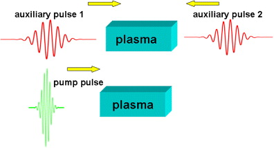
Figure 1. Schematic illustration of the IPA-LWFA scheme. In stage 1, two auxiliary long-pulse lasers counter-propagate in the plasma and pre-energize the electrons by exciting a plasma wave at the beat frequency. In stage 2, after the auxiliary pulses are gone, the short pump laser pulse propagates in the pre-modulated plasma and generates an accelerating wakefield.
Download figure:
Standard imageFor clarity, the IPA-LWFA scheme is first investigated using a 1D fully electromagnetic PIC simulation. The simulation box is located at 0 ⩽x ⩽ 200λ0, where λ0 is the wavelength of the pump laser in the acceleration stage, T0 = λ0 /c and ω0 = 2π/T0 are the laser period and angular frequency, respectively, and nc = ω02ε0 me /e2 is the critical density of the plasma. The uniform plasma layer of the initial density n0 = 0.04nc is located at 50λ0 ⩽x ⩽ 150λ0. At t = 0 , the two p polarized auxiliary laser pulses of frequencies ω1 = ω0 ω2 = 0.8ω0 are incident from the left and right boundaries, respectively. These lasers have identical profiles a = a0 sin(π t/τ) for 0 ⩽t ⩽ τ where a0 = 0.1 and τ = 100T0. The plasma and auxiliary-laser parameters have been chosen such that when the two pulses interfere in the plasma, an EPW at the beat, or difference, frequency is excited. At a time delay of ΔT = 100T0 with respect to the auxiliary pulses (which we recall are of duration τ = 100T0), an short intense pump laser pulse of intensity profile a = a0 exp [- (t − t0)2/τ02], where a0 = 2.0 and τ0 = 5T0, is launched from the left boundary. For comparison, normal LWFA with the same pump pulse and plasma is also simulated. We use absorbing boundary conditions for both the electromagnetic field and the particles. The ion motion is included in simulations. Since ions are too heavy to be influenced by the ponderomotive force of the laser, they keep nearly undisturbed in the entire simulation.
Figure 2(a) shows the electron phase space  at t = 145T0, just before the pump laser enters the modulated plasma. At this time, the excited EPW has saturated. The characteristics of the electron phase space are typical of externally or instability-driven plasma waves saturated by nonlinear Landau damping or trapping of electrons by the wave field [17, 18]. The trapped electrons can gain considerable energy from the propagating wave, accounting for the high maximum velocity (nearly 0.3c) of the electrons. Figure 2(b) is for t = 175T0, when the pump laser has entered the modulated plasma and an intense wakefield (in the following, the term wakefield refers only to that excited by the main laser pulse) is being excited, as indicated by the large longitudinal electric field Ex (black curve) in the affected region x < 70λ0. The inset in figure 2(b) shows the phase space of the electrons in the region x > 72λ0, where the nonlinear EPW excited by the auxiliary lasers is still unperturbed by the pump laser. As expected, the electric field there is consistent with that of driven plasma waves saturated by nonlinear Landau damping.

Figure 2. The electron phase space (red dots) at (a) t = 145T0 (before the main laser pulse arrives) and (b) t = 175T0 (after the main pulse has partially entered the plasma) from 1D PIC simulation. In (b) the black curve shows the longitudinal electric field Ex. In the inset the electron phase space in the still unaffected region is enlarged. Trapping and energization of electrons by the auxiliary-laser excited plasma wave can be clearly observed.
Download figure:
Standard imageFigure 3 shows the phase space (red solid circles) and the longitudinal electric field (black curves) of the IPA-LWFA electrons (right column) and the reference standard LWFA electrons (left column). The electron-accelerating phase buckets (where Ex < 0) of the wake wave are crosshatched. In figure 3(a), we see that self-injection of electrons has occurred, as pointed out by the blue arrow. These trapped electrons are accelerated and quickly outrun the local wakefield phase and enter the deceleration region, as can be seen in figure 3(c). At the same time, other electrons become trapped. In the IPA-LWFA case, the pump laser enters the pre-modulated plasma after a 100T0 delay with respect to the auxiliary pulses. One can see in figure 3(b) that at t = 220T0 many more electrons are trapped as compared with that in the standard LWFA case. That is, the self-injection process in IPA-LWFA is significantly enhanced, although the amplitude of the wakefield is actually lower than that in the standard LWFA case since the plasma is preheated. As shown in figure 3(d) for t = 255T0, after the first acceleration phase the wakefield becomes gradually weakened because of beam loading, and the width of the first acceleration bucket is increased.
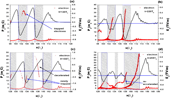
Figure 3. Phase space of the plasma electrons (red dots) and the longitudinal electric field Ex (black curves) corresponding to normal LWFA (left column) and IPA-LWFA (right column) at different times for the same plasma and laser parameters. The advantage of the latter scheme can be clearly seen.
Download figure:
Standard imageAs indicated by the blue arrow in figure 3(d), the second phase bucket is compressed and the electrons trapped therein can now traverse the deceleration region between the first and second buckets and enter the first acceleration bucket. The phase merging further contributes to enhancement of electron injection. The electrons in the first bucket have a broad energy spectrum, but as the wakefield propagates, the more (less) energetic electrons enter the deceleration (acceleration) region in the phase-space vortex, thus narrowing the energy spectrum.
In order to see the higher-dimensional effects such as focusing of the wakefield, 2D fully electromagnetic PIC simulations are carried out for both the IPA-LWFA and reference LWFA cases. The simulation box is 256λ0 × 32λ0 and the plasma is located at 5λ0 ⩽ x ⩽ 250λ0. In both the longitudinal and transverse directions, the absorbing boundary conditions are used. The auxiliary and pump pulses are transversely Gaussian and of width 8λ0 (full-width at half-maximum). The other parameters are the same as for the 1D simulations. Figure 4 shows the results for the IPA-LWFA case. The left column is for the electron density (normalized by nc and in the log scale). The right column is for the electron phase space  for electrons residing in the region 3λ0 < y < 30λ0. At t = 190T0 a trapped electron bunch as well as the periodic density modulation of the auxiliary-pulses excited EPW preceding the wakefield can be observed. As expected, at t = 215T0 the characteristic bubble profile of the first acceleration bucket can be clearly observed, but there are no other buckets. The phase space
  shows that the leading trapped electrons have entered the deceleration region, and new electrons from the back of the bubble are being injected and trapped. Since the bubble becomes elongated as it propagates and evolves, these electrons can be accelerated to higher energies. At t = 235T0, the originally trapped electrons enter the deceleration phase, while the latter trapped electrons are still being accelerated. At t = 280T0, phase merging similar to that found in the 1D simulation can be observed. The bubble is now much longer than that at t = 215T0. It becomes more like a channel and a quasi-monoenergetic electron bunch propagates in it, as indicated by the yellow dashed circle in figure 4(h).
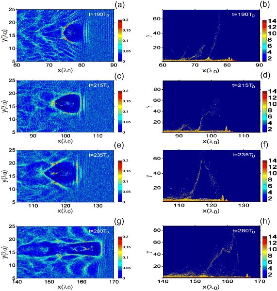
Figure 4. The density distribution (left column) and phase plots (right column) of electrons for the IPA-LWFA case by 2D PIC simulations.
Download figure:
Standard imageA comparison of the electron bunch charge from the reference LWFA and the IPA-LWFA schemes is given in figure 5. For the IPA-LWFA case, the time delay ΔT = 100T0 is subtracted from the figure. The total number of trapped charges in the first bucket is estimated by taking into account only electrons having energy larger than γtrap = 5, since an electron can be trapped only if its velocity approaches the wakefield phase velocity  . The electron bunch width in the z-direction is taken to be 10λ0.

Figure 5. The electron bunch charge for the LWFA and IPA-LWFA cases from 2D PIC simulations. For the IPA-LWFA case, the time delay 100T0 is subtracted.
Download figure:
Standard imageIn both cases, the bunch charge slowly increases from t = 50T0, becomes saturated at t ∼ 100T0, after which it begins to decrease in the standard LWFA case. For the IPA-LWFA case, however, not only is the charge higher, but it also remains almost constant at around 500 pico-Coulomb (pC) after the saturation for a much longer time. Thus, the IPA-LWFA scheme can indeed enhance the charge of the electron bunch.
Figure 6(a) shows the effect of the intensity of the auxiliary laser pulses on the peak value of the trapped charges in the IPA-LWFA scheme from 1D PIC simulations, with the plasma and other laser parameters the same as before. Again, only electrons in the first bucket having energies larger than γtrap = 5 are included. For definitiveness, the cross section of the electron bunch is taken to be circular, with radius 10λ0. We see that the intensity is optimized for a0 ∼0.1, which results in a bunch charge of about 600 pC. If the auxiliary pulses are either too weak or too intense, the bunch charge is significantly reduced. This is because (i) weaker auxiliary pulses cannot sufficiently pre-energized the plasma electrons, so that the acceleration process becomes similar to that of the standard LWFA, and (ii) if the auxiliary pulses are too strong (say a0 > 0.5), the plasma electrons become too hot and their motion becomes chaotic, so that the intensity of the wakefield is lowered.
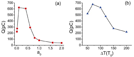
Figure 6. Evolution of the peak value of trapped charges with the auxiliary pulses' intensity (a) and the time delay (b) for the IPA-LWFA case by 1D PIC simulation. The electrons located in the first bucket and with energy higher than γtrap = 5 are counted. The cross section of the electron bunch is assumed to be a circle with radius 10λ0.
Download figure:
Standard imageIn figure 6(b) the effect of the time delay ΔT of the pump laser is shown. The peak value of the bunch charge first increases with ΔT and attains a maximum at ΔT = 70T0, and then it decreases as ΔT further increases. Thus, we see that the pre-heating of electrons by interfering auxiliary pulses needs some time to develop, but too much heating is disadvantageous for IPA-LWFA of electrons.
3. Conclusion
In conclusion, the IPA-LWFA scheme for producing a monoenergetic electron bunch with high charge has been proposed and investigated by 1D and 2D PIC simulations. In this scheme, two low-intensity long pulses interfere to create a finite-amplitude slow-propagating EPW in the plasma before the intense wakefield-driving pulse is launched. The plasma density is thus modulated and the electrons are slightly heated. An enhancement of electron injection into the wakefield is thereby achieved. The effects of the intensity of the auxiliary pulses and the time delay of the launch of the pump laser on the charge of the resulting electron bunch from IPA-LWFA have been examined and compared with that from normal LWFA.
Acknowledgment
This work was supported by the Natural Science Foundation of China (grant numbers 11175255, 10835003 and 11275269).