
Abstract
In the framework of the Future Circular Collider Study a new septum magnet concept, nicknamed 'SuShi' has been developed, and a prototype was built at Wigner Research Center for Physics, and tested at the FREIA facility of Uppsala University in April 2023. The concept uses a canted cosine theta (CCT)-like superconducting magnet and a passive superconducting shield to create a zero-field and high-field region within its aperture. SuShi is the first CCT magnet with both of its winding layers simultaneously impregnated with wax. This paper describes the first powering test of the empty magnet at 4.2 K, without the shield being inserted in its aperture. The performance of the magnet, including the observation of quench-back, estimation of hot-spot temperatures and the fraction of energy dissipated in the magnet are presented, and most interestingly the absence of any quench during the entire testing period is reported. Sushi reached its nominal +5% peak field of 3.64 T at 450 A, which corresponds to 80% of the calculated short sample limit along the load line, without training.
Export citation and abstract BibTeX RIS

Original content from this work may be used under the terms of the Creative Commons Attribution 4.0 license. Any further distribution of this work must maintain attribution to the author(s) and the title of the work, journal citation and DOI.
1. Introduction
Fast (single turn) extraction of particle beams from an accelerator ring is generally made by a fast kicker magnet in combination with a more powerful septum magnet, which has a zero-field channel for the circulating beam, and a high-field channel for the kicked/extracted beam. In high-energy accelerators, the beam is ejected from the ring at the end of a fill, and also when a beam abort flag is raised at any other moment during ramp-up or coast of the beam. The extraction kicker generators and septum power converters follow the beam energy by charging the pulse-forming network to voltages, and setting the septum currents to values corresponding to the actual beam energy, respectively [1].
The Large Hadron Collider (LHC), the highest-energy proton-proton collider today, uses normal-conducting Lambertson septum magnets [2, 3] with a magnetic field up to 1.17 T. The Lambertson septum concept was used earlier in the CERN Intersecting Storage Rings (ISR) with a maximum field of 1.48 T [4]. The working principle of these septum magnets is based on having nearly zero field in an air domain embedded in an iron yoke. Since this effect breaks down at saturation, Lambertson septa can not achieve significantly higher fields than the two examples given above. Application of Lambertson septa for the Future Circular Collider (FCC) has been studied in detail in [4]. The required physical length and power consumption were found to be 164 m and 2.2 MW per beam, respectively. Application of cobalt steel in the Lambertson septum (which has a saturation around 2.35 T) was excluded due to the possible activation of cobalt, and cost and availability issues associated with this material in large quantities needed for the FCC. Septum magnets using permanent magnets have the drawback that they can not be ramped, and are therefore inadequate for high-energy rings such as the LHC and FCC where a beam abort at any energy between injection and maximum is necessary.
The FCC reference design [5], therefore, is based on superconducting septum magnets, which give a total deflection of the beam by 2.4 mrad towards the extraction line. Two types are presently foreseen: 3 T thin septa of a total length of 10 m (using the SuShi topology [6–8], which utilizes a passive superconducting shield to create the field-free channel within the bore of a superconducting magnet, and was conceptualized for the FCC) followed by 4 T truncated cosine theta (TCT) septa of a total length of 40 m [9] which have a bigger septum thickness. The principal parameters of these devices are shown in table 1.
Table 1. Principal parameters of the FCC extraction septa.
| Parameter | Unit | Thin septa | Thick septa |
|---|---|---|---|
| Topology used | SuShi | TCT | |
| Number of magnets | 9 | 24 | |
| Magnet length | m | 3 | 4 |
| Magnetic length per unit | m | 2.5 | 3.5 |
| Septum thickness | mm | 25 | 30 |
| Gap height | mm | 25 | 25 |
| Gap field | T | 3 | 4 |
| Relative field homogeneity | 10−2 | 10−2 | |
| Relative integrated leak field |

|

|
To date there is only limited operational experience with superconducting septa. A conceptual design was proposed in [10]. The KEK 12 GeV proton synchrotron applied a superconducting septum magnet designed for 2 T and operating at 1.46 T for a secondary beam line [11]. The experiment E94-107 at Jefferson Lab used a superconducting septum for hypernuclei spectroscopy [12]. The TCT septum magnet concept [13] was used for the BNL g-2 inflector [14]. The latter is of special interest from the FCC's point of view, since both concepts proposed for the FCC are based on a technology that was already present in this magnet. The passive superconducting shield of the g-2 inflector, used to contain the stray field of the magnet, was turned into the key component of the SuShi septum concept, creating a zero-field channel within a high-field domain. The TCT septum shares the basic concept with the g-2 inflector.
In the framework of a collaboration between CERN and Wigner Research Centre for Physics (Budapest), a sub-scale demonstrator SuShi septum magnet was designed, constructed and tested. The initial purpose of this prototype was to demonstrate the feasibility of the concept either for the FCC or elsewhere, to measure its characteristics such as field quality, field stability, flux jump detection, etc and to gain experience. During the course of the project it developed a more general goal and served as a practicing and development framework for canted cosine theta (CCT) magnets in general, and for work packages 8 of the HITRIplus and I.FAST projects [15] in particular.
This article describes the initial tests of the empty prototype SuShi magnet, i.e. without the shield. Sushi is a CCT-type magnet [16, 17] consisting of a pair of concentric coils that are tilted at opposite angles. The winding geometry is different from a simple dipole CCT magnet to take into account the effect of the shielding tube on the field pattern, as described in [8].
CCT technology is gaining attention lately due to its simplicity compared to cosine theta magnets. In the few Tesla range, CCT magnets are cheaper (despite their ineffective usage of superconductor), easier to wind and to adapt to nontrivial field patterns (e.g. the case of SuShi, combined function, or curved magnets [18]).
An important novelty of SuShi is that it has been impregnated with wax. To our knowledge, it is the first CCT magnet where all winding layers were impregnated with wax simultaneously, in the same process. Although the CCT topology is well suited for wax impregnation due to its stress-managed nature, and the impregnated volume being fully enclosed, the impregnation process itself poses some difficulties. The complicated geometry of narrow channels can easily lead to the blockage of wax refill paths during freeze-out, and thereby to the formation of voids when wax contracts by 15% upon solidification.
The application of wax in superconducting magnets is not without precedence. In the very early days of filamentary conductors, the first test was made with wax in order to save the very precious wire for later tests [19]. The magnet reached its nominal current without training. Fears about conductor movement over long-term operation in ramped magnets led to the switchover to epoxy, which introduced training.
Wax was also one of the standard impregnation materials in commercial Magnetic Resonance Imaging (MRI) magnets. Details of these devices are typically industrial secrets, but two major vendors (Siemens [20] and GE [21]) explicitly mention wax in their devices. Oxford Instruments (active both in the accelerator and MRI domain) also mentions wax impregnation among their technologies [22]. Wax was also successfully applied in a 9.4 Tesla high-temperature superconductor Nuclear Magnetic Resonance (NMR) spectrometer magnet [23]. However, when striving for high fields, wax proved to be insufficient to sustain the high pressures [24]. Wax was found to be squeezed out from unclosed U-shaped channels without a stress-management structure [25]. The BOX (BOnding eXperiment) project at PSI also reported a degraded performance of wax-impregnated samples under high external pressure, though the performance of wax was significantly improved up to 150–160 MPa transverse stress by improving the method of impregnation, bringing the reachable critical current on a par with samples impregnated with CTD101K [26].
Magnets of particle accelerators produce a transverse field in a long, clear aperture where the beam is passing through. This requires a large axial current density component, realized most often by the widespread 'cosine theta' configuration. Here, the winding is typically a self-supporting component. For the LHC dipole magnets, the Rutherford cables have 3 layers of polyimide tape wraps, the outermost having a polyimide-based adhesive coating. The self-supporting feature of the winding is achieved via polymerization [27, 28]. Wax would not be able to replace epoxy in these magnets due to its lack of rigidity, lack of bonding, and the impregnated volume being unconfined, leading to wax fall-out over time. Therefore, wax did not find widespread application in superconducting accelerator magnets so far. This situation seems to be changing recently. The BOX project at Paul Scherrer Institute and the University of Twente is carrying out a systematic study of the training behavior of different impregnation materials in a simple cable-in-groove setup, and reported a training-free performance of wax reaching the short-sample limit at the first attempt [29]. At Lawrence Berkeley Laboratory, a CCT-type magnet prototype was partially impregnated with wax, and no quench occurred in the wax-impregnated layer during testing. A fully wax-impregnated CCT magnet (with its two layers being impregnated separately) is expected to be tested in the near future. The test results are going to be published soon [30].
Although a 2.4-Tesla non-impregnated NbTi CCT magnet performed well without impregnation [31], conductor-in-groove type magnets (such as CCTs) are typically impregnated. Non-impregnated Nb3Sn samples showed a significantly reduced performance with respect to impregnated samples [32]. As illustrated above with the example of the LHC dipoles, some other magnet types do not require impregnation but other technologies. For the activation and bonding of the adhesive layers of the LHC dipole winding a minimum temperature of 185 °C and a pressure of 60–100 MPa are required, and the corresponding infrastructure (controlled-tension tape wrapping, temperature control, large press, etc) [27, 28]. Although a direct comparison between high-field magnets in the 8 Tesla range and CCTs targeting the 3–4 Tesla range is not appropriate, it must be noted that impregnation in case of the latter is not an additional required technology but the replacement of another one. Once the initial difficulties introduced by the contraction of wax during freeze-out are mastered, the process is simple, requiring only moderate temperatures (~70 °C) without precise temperature control and simple, commercial hardware (a vacuum pump with modest requirements, heater tapes and cheap heat insulation, temperature sensors, pressurized air and piping).
This paper begins with the description of the magnet design and its manufacturing process (section 2) before moving to the experimental setup used for the test (section 3). Section 4 details the results and is followed by the conclusions and the outlook for future tests with the shield.
2. Magnet design and manufacturing
This section gives only a brief overview of the magnet design and manufacturing procedure. More details will be provided in a separate paper.
The SuShi septum magnet creates a zero-field channel within its aperture using a half-moon shaped passive superconducting shield and the persistent currents excited in it during the ramp-up of the magnet (figure 1). The concept and the R&D process are described and illustrated in more detail in [6–8].

Figure 1. Cross section of the SuShi septum magnet, and the generated field pattern.
Download figure:
Standard image High-resolution imageThe magnet design is based on the CCT concept:  NbTi strands of the LHC dipole type are wound into grooves machined into cylindrical mandrels, called formers. The high-luminosity LHC twin-aperture orbit corrector magnet [33] was used as a reference design. Some design improvements, such as the layer jump configuration, the winding path optimization, and the azimuthal locking of the tubes without openings through the walls are shown in [8]. The magnet parameters are summarized in table 2. The formers were machined from aluminium 6082-T6 and received a 40 micron thick hard anodized layer (figure 2(a)), serving both as an insulator and a smooth coating to assist the sliding of the winding tooling.
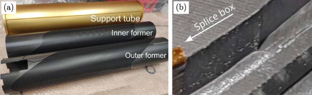
Figure 2. (a) Picture of the inner and outer formers, and the support tube of the magnet. See [8] for more info on the winding shape. © [2022] IEEE. Reprinted, with permission, from [8]. (b) Machining flaw causing damage to the wire insulation, visible if properly lit.
Download figure:
Standard image High-resolution imageTable 2. Parameters of the magnet.
| Parameter | Symbol | Value | Unit |
|---|---|---|---|
| Aperture diameter | A | 105.35 | mm |
| Length | L | 800 | mm |
| Groove width | d1 | 2.1 | mm |
| Groove depth | d2 | 5.1 | mm |
| Strand diameter | Dw | 0.825 | mm |
| Spar 1 thickness |

| 4 | mm |
| Spar 2 thickness |

| 2 | mm |
| Support tube wall thickness |

| 12.5 | mm |
| Radial gaps between tubes | G | 0.725 | mm |
| Pitch | P | 5.24 | mm |
| Minimum rib thickness |

| 0.35 | mm |
| Number of turns | n | 102 | |
| Nominal current | I0 | 429 | A |
| Nominal field (with shield) | B0 | 3 | T |
| Inductance (without shield) |

| 189 | mH |
| Stored energy (without shield) |

| 17.4 | kJ |
| Peak field in coils (without shield) |

| 3.64 | T |
| Short sample critical current |

| 703 | A |

| 61 | % | |

| 76 | % |
During winding, quite a few insulation problems were discovered by high-voltage tests, made every few turns applying 1 kV between all ten strands (at the same potential) and the formers. When these problems occurred in the first few turns, the winding process was restarted from scratch, and the damaged section of the given strand was cut off. Otherwise, only the last few turns were unwound, the damage was located and fixed by self-adhesive Kapton tape.
These problems had several reasons. A few of them were caused by small sharp features inside the grooves (hardly visible to the naked eye) due to manufacturing flaws. These features had to be removed by hand using tiny abrasive tools. This step unavoidably removed the hard-anodized layer in the surrounding domain as well. A particular case was a sharp feature at the transition between the initial section of the groove (coming from the splice box) and the first turn of the regular winding pattern due to a CAM (computer-aided manufacturing) programming flaw: the tool paths of two separate machining runs did not sufficiently overlap (see figure 2(b)). A further reason for the insulation problems was the insufficient rounding of the grooves' edges, which easily damaged the insulation of the bottom strand at the inner side of the groove's curvature during winding. Finally, the strands, supplied to us from the remaining spools of the LHC dipole magnets in CERN's stock, also had some insulation damage at a few spots.
The majority of the insulation problems occurred during the winding of the inner former. The outer former was free from manufacturing flaws, and the team also had gained more experience with winding. Only a single short was observed on the outer former.
Both winding layers were wrapped with a 30 mm wide, 0.1 mm thick glass-fiber tape in two passes. In the first pass there was a 50% overlap between subsequent turns, the second pass was made without overlap. Two layers of a kapton sheet (0.1 mm each) were added around the glass fiber layers. The next tubes (either the second winding layer, or the external support tube) could then be installed with practically no radial play, but without a large friction. They received a mold release agent coating on their internal surface (Chemlease 2298) to inhibit the bonding of the epoxy filler to them and thereby avoid crack initiation at this interface. This coating lost its relevance later when epoxy was dropped in favor of wax. On one hand, the glass fiber layers act as a spacer to ensure a transfer channel for liquid wax below the kapton layers, in direct contact with the grooves. On the other hand, glass fiber acts as a retainer of wax and provides a better mechanical consistency.
The 10 strands (running forward around the inner former and returning on the outer former) were connected in series in a 'praying hands' configuration at the current lead end of the magnet, in the splice box (figure 3), in the same way as it was done for the high-luminosity LHC corrector magnets [33]. Unfortunately, the strands of one of the splices got twisted inside the crimp sleeve, and one of them was cut short by the other strand when crimped (figure 3(b)), making it impossible to use the praying hands configuration for this splice. The problem was finally solved using two bridging strands jointed to the original strands in a shaking hands configuration, as shown in figure 3(b). Using two strands in parallel was believed to make the resistance of the splice about a factor of two lower, compensating for the increase by the same factor due to two splices being in close proximity along the same strand. Voltage tap wires were soldered to both sides of all splices, except this problematic one.
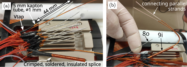
Figure 3. (a) Illustration of splicing ('praying hands'). (b) Solution to fix the problematic splice: two parallel cables are bridging the connection between the strands marked by 8o and 9i in 'shaking hands' configuration.
Download figure:
Standard image High-resolution imageImpregnation (originally planned with CTD 101 K epoxy) was preceded by the results of the BOX experiment at the Paul Scherrer Institute [29], demonstrating a training-free performance of short samples of Nb3Sn cables impregnated with paraffin wax. The choice of materials for magnets in a high-radiation environment, such as that of extraction septa, is crucial, and radiation-hardness of wax has yet to be proven in dedicated experiments. However, this prototype was not planned to be installed in a machine but to demonstrate the shielding concept and evaluate its characteristics. The excellent training behavior of wax (offering a fast way to the true goal of this project) and the possibility to unmold the magnet and spare the costly formers in case of magnet failure were the key factors to finally choose wax for the impregnation. The experience gained during the R&D and construction phase then had a direct utilization in work packages 8 of the HITRIplus and I.FAST projects [15]. A quick R&D campaign was launched at Wigner RCP to develop a void-free impregnation method for this complicated geometry, dealing with the significant volumetric contraction of wax upon solidification, which was measured to be about 15%. The developed method controls the progression of the solid-liquid interface by the simultaneous application of heating and cooling in a very simple setup [34], ensuring open, unfrozen channels for liquid wax refill from a local reservoir at the top of the magnet at all times. The entire magnet, i.e. both winding layers, were simultaneously impregnated in the same process with paraffin wax (MOL FR DWC 5456_MOL_0812_002). During cool-down, a pressure of 5 bar was applied to the reservoir. The method and its development will be published in a separate paper. Unfortunately, the required volume of the wax reservoir was miscalculated, and the reservoir ran empty by the end of the impregnation, leaving about 5–6 cm at the top of the magnet (half of the splice box and short sections of the last few turns) dry. This was fixed by re-warming the top of the magnet (ensuring a vertical temperature gradient) and topping up with liquid wax under vacuum, then cooling down under a pressure of 5 bar.
After the impregnation with wax, the insulation was tested by a Megger MIT525 high-voltage tester at 1.1 kV. After a measurement period of 60 s, the measured resistance between the winding and any of the two formers was about 14 GΩ, and that between the winding and the yoke was 53 GΩ. These were considered safe for a magnet current of 450 A and a dump resistor of 0.7 Ω, giving a maximum inductive voltage of 315 V.
3. Experimental setup
The Sushi magnet was tested at 4.2 K in the vertical cryostat Gersemi [35] of the FREIA (Facility for Research Instrumentation and Accelerators, Uppsala University, SE) laboratory. The cryostat is equipped with a dedicated magnet insert containing a lambda-plate, which allows operation between 4.2 K and 1.9 K maintaining the liquid helium bath at atmospheric pressure [36], providing a maximum current of 2 kA DC with 4 hybrid current leads (copper + NbTi).
The voltage tap wires (connected to the splices within the magnet and to different spots along the leads) were connected to the 'Potential Aimant' (PotAim) cards of the quench protection system to monitor direct or differential voltages and trigger the quench protection protocol if necessary [36]. Several circuits were used to avoid being blind to symmetric quenches and for redundancy. Without listing all, there was a differential voltage measurement between Splice C, Vtap 5o and Splice D (see figure 4), and another one between Vtap 2o, Vtap 4o and Vtap 6o to detect a symmetric quench, to which the previous circuit was insensitive. The threshold and validation times for the differential and the direct voltages were 100 mV for over 2 ms and 10 mV for over 8 ms, respectively. In case of a quench, the energy extraction (EE) system couples a dump resistor  = 0.7 Ω into the circuit via IGBT switches [37]. The choice of the dump resistor's value will be reasoned later.
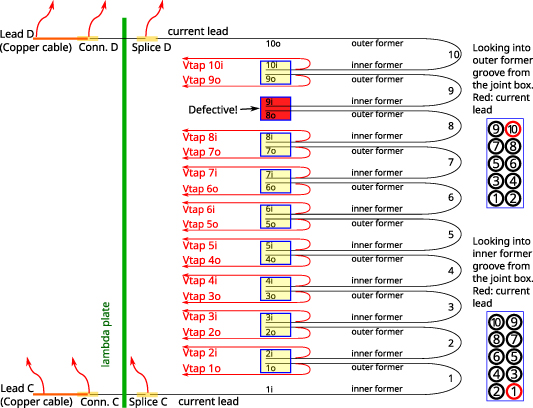
Figure 4. Test magnet circuit schematic. The red arrows indicate  connected to the PotAim cards.
Download figure:
Standard image High-resolution imageTwo different acquisition systems, called DAQ and DMM (digital multimeter), recorded the signals of the voltage tap wires. The DAQ is used to acquire the signals coming from the magnet after the detection of a quench. Two types of data acquisition are in place, low frequency (LF) and high frequency (HF). 72 channels can be monitored in LF with an acquisition frequency of 1 kHz and 16-bit resolution. Further 48 channels can be recorded at HF with an acquisition frequency of up to 200 kHz and 16-bit resolution. The DMM system is used for continuous measurements. It has 10 acquisition channels with a resolution from  to 10
to 10  . The acquisition time of the DMM can be manually regulated depending on the requirements. The DMM was used to measure splice resistances, magnet inductance, and the residual resistivity ratio (RRR) of the strands.
4. Test results
In the initial series of tests, the magnet was powered to different (increasing) currents with a ramp rate of 1 A s−1, reaching nominal operating current without a single quench. At each current level, the energy extraction system was manually triggered after about 1 min to study the current decay in the magnet, and thereby estimate the eventual hot spot temperature, before powering the magnet with a higher current. Figure 5(a) shows the I(t) curves during the first second after the trigger, normalized to their initial value.
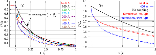
Figure 5. (a) Current vs. time plots during manually triggered energy extractions at different magnet currents. All curves have been scaled to their initial value before the trigger. (b) Comparison of the measured decay curves at 52.3 and 400 A with a lumped-element circuit simulation with or without quench-back (see text for details).
Download figure:
Standard image High-resolution imageWhile the curves at I0 = 53.2 and 100 A perfectly overlap, indicating a linear behavior of the magnet, the curves at 150 A and above systematically deviate from the previous ones. This deviation seems to be gradual as a function of time for I0 = 150 and 175 A, but for higher currents there is a distinct moment in time (indicated by arrows) when these curves significantly separate from the low-current ones. This behavior is attributed to the onset of quench-back: eddy currents induced in the bulk aluminium formers heating the entire coil above Tc . The suddenly developing coil resistance (268 mΩ in zero field and at 10 K, see the end of this section) is of the same order of magnitude as the dump resistor (0.7 Ω). With higher magnet currents the onset of quench-back occurs earlier, in agreement with expectations [38].
Due to the time range of the high-frequency sampling being set to 1 s after the trigger, the tails of the I(t) curves have been cut off. In order to account for this when calculating the quench integral  , the measured current decay curves have been fitted with a simple exponential function
  above 0.25 s, where A and τ were the fitting parameters. The fits gave a very precise agreement with the data. The cut-off quench integral was estimated as
  (with t0 = 1 s) and added to the numerical integral of the measured decay curves in the time range [0..1 s]. This correction decreased from ~0.6% at 52 A to below 0.05% at 450 A.
Figure 6(a) shows the quench integral calculated this way at different current levels. Figure 6(b) shows the adiabatic hot-spot temperature of the given strand as a function of the quench integral, at two different magnetic field levels. Figure 6(c) shows the estimated hot-spot temperature as a function of magnet current, assuming B = 0 T. The temperatures stay below 50 K even for the highest current of 450 A. The dump resistor's value was chosen based on figure 6(b). Assuming a purely exponential current decay, the dump resistor's value giving a quench integral M is  where I0 is the magnet current (450 A) and L is its inductance (189 mH). A value M =
  A2s gives a temperature below 150 K, which results in
  = 765 mΩ. The nearest available value, 0.7 Ω was used for the measurements, giving a moderate maximum voltage of 315 V.
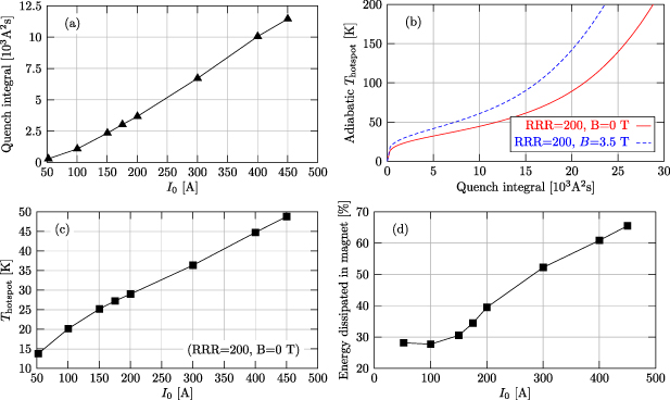
Figure 6. (a) Quench integral (including the validation time) as a function of magnet current. (b) Adiabatic hot-spot temperature as a function of the quench integral. (c) Estimated adiabatic hot-spot temperatures as a function of the magnet current in the case of a quench. (d) Fraction of the stored magnetic energy dissipated in the magnet as a function of the magnet current.
Download figure:
Standard image High-resolution imageIn order to illustrate the beneficial effect of the formers for quench protection, figure 6(d) shows the fraction of the stored magnetic energy dissipated in the magnet, which was calculated as

It increases from 28% at 53.2 A to 65% at 450 A.
In order to understand the observed phenomena in the current decay curves, and clearly attribute the breakdown of the I(t) curves to quench-back, a simple lumped-element simulation was made assuming 4 inductive, mutually coupled loops: (1) the magnet winding with the dump resistor and (2–4) the eddy currents in the inner and outer former, and the outermost support tube. Their behavior is described by the transformer equation

where L is the inductance matrix and R is the diagonal resistance matrix:  with ri
being the lumped-element equivalent (LEE) resistance of the loop i. I1 is the magnet current and Ii
(i = 2..4) are the total currents associated with the eddy current loops, which need not be defined as will be shown below. Introducing the scaled currents
with ri
being the lumped-element equivalent (LEE) resistance of the loop i. I1 is the magnet current and Ii
(i = 2..4) are the total currents associated with the eddy current loops, which need not be defined as will be shown below. Introducing the scaled currents  the scaled transformer equation (2) can be written as


where  are the coupling factors and
  are the time constants.
In order to estimate the LEE parameters, a homogenized-winding 3D model of the magnet was constructed in COMSOL where the windings were approximated by a contiguous domain within their envelope (i.e. assuming no ribs between the turns), and a continuous current density distribution describing the effective, average current density of the discrete wires was prescribed in these domains. The magnet current was ramped down with a rate typical to an energy extraction (−400 A s−1) and the induced eddy current patterns were captured in all 3 aluminium tubes. The elements of the inductance matrix were then calculated using the magnetic energy integrals:


where Eij is the magnetic energy integral when only the currents in the loops i and j are present, and all other ones are set to zero.
The time constants of the eddy current loops are calculated based on the power of distributed resistive losses which cause an exponential decay in energy:

Using the resistivity of aluminium  Ωm (calculated by the library provided with the ProteCCT simulation tool [39], assuming an RRR of 8 and temperature of 4.2 K), the parameters of the transformer equation are shown in table 3. Equation (3) was solved numerically with the initial conditions
  and
and  (i = 2..4). This latter condition allows to disregard the magnitude (i.e. the exact definition) of the eddy currents. The magnet current was obtained as
  . This simulation framework was the initial part of a much more sophisticated quasi-3D, transient, multi-physics quench simulation software which did not reach completion. The advantage of this approach is that different phenomena and sensitivity to the parameters can be very quickly simulated, and a transient, true 3D finite-element simulation only needs to be run initially for a short time period to estimate the parameters of the lumped-element equivalent circuit.
Table 3. Lumped-element equivalent parameters of the coupled inductive loops model, as calculated from the COMSOL model. For the reproduction of the experimental curves (figure 5(b)), the coil-to-formers couplings were increased by 3.5%.
| kij | |||
|---|---|---|---|
| 1 | 0.857 | 0.923 | 0.873 |
| 0.857 | 1 | 0.855 | 0.741 |
| 0.923 | 0.855 | 1 | 0.862 |
| 0.873 | 0.741 | 0.862 | 1 |
| τi (ms) | |
|---|---|
| τ1 | 270 |
| τ2 | 12.7 |
| τ3 | 17.2 |
| τ4 | 86.2 |
Figure 5(b) shows two experimental I(t) curves at 52.3 and 400 A, compared to simulated ones. After a slight adjustment of the winding-formers coupling factors  (i = 2..4) by +3.5%, the simulated curve perfectly describes the initial part of the experimental decay curve at 52.3 A. To reproduce the break-down visible in the 400 A curve, further adjustment of the parameters of this model was not sufficient. An extra resistance had to be added to the primary loop (i.e. the magnet winding + dump resistor circuit), which was increased linearly from 0 to
  between t1 and t2, corresponding to the developing coil resistance during a quench-back. The parameters t1 = 11 ms, t2 = 20 ms were found to give a decent agreement with the experimental curve. The coil resistance had to be chosen as 3.2-times the coil resistance measured at 10 K and zero field (268 mΩ, see at the end of this section) to achieve a good agreement with the measurement. In general, matching a decay curve for a larger magnet current was not possible by only adjusting the onset of the quench-back to earlier times. Increasing the coil resistance in the simulation was also necessary, otherwise, the amount of current drop could not be reproduced. This is expected since larger magnet currents cause both a higher temperature of the formers and a higher magnetic field, both of which increase the resistivity of copper. Temperature measurements in the former (see figure 7) indicate a temperature of about 20 K at the highest magnet current which can cause a reasonable increase of the coil resistance with respect to the value measured at 10 K. The agreement between the simulated and measured current decay curves is surprisingly good, despite the serious simplifications made in the simulation.

Figure 7. (a) Temperature measured on the inner former during energy extraction at 450 A. The measured time has an unknown offset from the manual trigger. (b) Inductance measurement of the magnet at 10 A s−1. The dashed red line shows the magnet current, which is fit by the 10 A s−1 slope (black dotted line). The solid blue line shows the measured voltage and the dashed blue line shows its average within the time interval [15–45 s].
Download figure:
Standard image High-resolution imageCoupling to the formers renders the effective inductance of the magnet smaller at early times, due to the eddy currents being initially zero. The magnet current can decrease much faster (as clearly visible in the data and the simulation) with respect to a simple exponential decay since the rising eddy currents compensate for its decrease and try to maintain the magnetic field level and  . At t = 0 the induced magnet voltage (depending only on
  and the winding geometry) equals the resistive voltage across the dump resistor,
  . I0, and hence
  are the same for the no-coupling and coupling cases, despite the fact that the magnet current decays much faster in the latter case. The trend swaps at later times (after ~0.3 s) when the decay of the eddy currents due to the formers' resistance induces a forward voltage in the winding and tries to keep the winding current high.
The observed decay curves are qualitatively very similar to those reported in [40, 41]. However, while the authors of [40] attribute the quench-back to the direct heating of the conductor by interfilament coupling losses, our interpretation agrees with that of [42], i.e. quench-back being due to indirect heating via the eddy currents in the formers, based on the arguments given above.
An endurance test of 1 hour at a magnet current of 450 A, and powering tests at different ramp rates up to 10 A s−1 showed no observable fluctuations or anomalies in any of the monitored signals of the magnet.
The temperature of the inner former was monitored at a sampling rate of 1 Hz by a Carbon Ceramic sensor (CCS) glued in a slot directly on the former surface. The measured temperature peaked at about 19 K during an energy extraction at 450 A and relaxed to the ambient temperature in about 15 s as seen in figure 7(a). The temperature sensor glued to the outer former has lost its electrical connection during cool-down and could not be used for measurements.
The magnet inductance was measured during ramps with different rates. Figure 7(b) shows an example at 10 A s−1 ramp-up. The voltage across the magnet (between Splice 'C' and 'D' in figure 4) stayed constant during the linear part of the ramp and averaged to 1.895 V, giving an inductance of 189.5 mH in perfect agreement with the value obtained from the simulation. Inductance values obtained at lower ramp rates were in agreement with this value, indicating the insignificance of eddy currents in the bulk components at such low ramp rates.
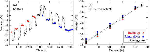
The resistances of the splices were measured by ramping to and pausing at 10, 100, 200, 300, 400 and 450 A (and back), and recording the voltages across the splices (figure 8(a)). The voltages were averaged on the plateaus and plotted as a function of magnet current (figure 8(b)). Values at the same current measured during ramp-up and ramp-down had a significant relative offset, which is attributed to eddy current loops with a large time constant. Their average was fitted with a straight line, the slope of which defined the splice resistances:  ,
,  ,
,  ,
,  ,
,  ,
,  ,
,  ,
,  ,
,  nΩ for the 9 splices respectively. The results for splice 8 have no significance due to the large inductive noise on two entire turns of the winding, between V
 8i-9o (figure 4).
Figure 8. Splice resistance measurement. (a) The voltage measured across splice 1 as a function of time. The colored line segments indicate the plateaus for averaging the voltages. (b) Averaged voltages as a function of magnet current on the plateaus.
Download figure:
Standard image High-resolution image
Upon completion of the tests, the magnet was warmed up slowly while being powered with a constant current of 100 mA. The RRR of the strand's copper matrix was determined by the ratio of voltages measured across a given section of the winding at room temperature (282 K) and just above the critical temperature of NbTi (10 K). To eliminate eventual offsets of the voltmeter, the voltages measured at 4.2 K were subtracted from all values. The voltages measured between Splice C and Splice D (including the whole magnet and the current leads, see figure 4) were  V, 0.0268 V and 5.26 V at 4.2, 10 and 282 K, respectively, which leads to a calculated RRR = 197 of the whole magnet. Without the current leads (i.e. between V
 1o-10i) the result was RRR = 200.
5. Conclusions and outlook
The SuShi septum magnet is a combined device that will create a high-field and a zero-field region within its aperture in close proximity, using a CCT-like winding and a passive superconducting shield. The winding geometry has been optimized to give a homogeneous field in about half of the aperture in the presence of the shield. The empty magnet (i.e. without the shield) was tested in the Gersemi cryostat of the FREIA facility of Uppsala University. The magnet is the first CCT-like magnet having both of its winding layers simultaneously impregnated with wax. Despite the manufacturing issues (incomplete impregnation and the subsequent topping up with wax, a repaired internal splice, and insulation problems with the strands) the magnet demonstrated excellent performance, not quenching a single time during the entire test, up to the highest tested ramp rate of 10 A s−1 and peak field of 3.64 T at 450 A (80% of the short sample limit). At low magnet current, the current decay curves measured during energy extraction could be reproduced by a simple lumped-element model with 4 inductively coupled loops, corresponding to the magnet winding with the dump resistor, and the eddy currents in the 3 supporting aluminium tubes. The parameters of this simple model were estimated from a 3D finite-element simulation and required only a minimal adjustment (increasing the coil-to-formers coupling factors by 3.5%). For the reproduction of the break-down of the decay curves observed above 175 A, an extra resistance with realistic values (few times the coil resistance measured at 10 K in zero field) had to be switched into the primary loop. These constitute a consistent picture, attributing the break-down of the decay curves to the onset of quench-back. As a consequence of quench-back, the energy dissipated in the magnet increased from about 28% to 65% at the highest magnet current. The adiabatic hot-spot temperature for eventual quenches is estimated to be around 50 K. The splice resistances were between 5–8 nΩ.
These results confirm the excellent performance of paraffin wax in a CCT-type magnet, reported earlier by the BOX experiment at PSI/University of Twente in a short sample test, and indicated by the absence of quenches in the wax-impregnated layer of a Nb3Sn CCT magnet made at Lawrence Berkley Laboratory. The developed impregnation method—dealing with the 15% contraction of wax upon solidification—proved to be robust and simple, requiring no expensive infrastructure. Combined with the very low price of wax, its low melting temperature, its non-toxicity, easy handling, the reversibility of the impregnation, and the fault tolerance of the impregnation method (partial impregnation and following topping-up), wax is certainly an attractive impregnation material for moderate-field magnets (around 3–4 T) with a CCT-like topology. The impregnated volume in such magnets can be fully enclosed within a container, prohibiting the fall-out of wax over time. Due to the stress-managed nature of this configuration (the entire winding being supported by a rigid mechanical structure turn-by-turn), wax only needs to act as a filler material, and does not need to provide the mechanical rigidity of the winding. Repeated tests must still assess long-term performance. Radiation hardness of wax still needs to be assessed by dedicated experiments to verify if wax-impregnated magnets can be safely operated in high-radiation environments.
The ultimate goal of this project is to evaluate the performance of the combined device, i.e. the magnet with the shield. Therefore these initial tests were conservative and did not attempt to push the magnet to its ultimate limits. Further tests with a half-moon shaped MgB2 shield are planned later this year in the SM18 facility of CERN R&D of the manufacturing technology of a multilayer NbTi/Cu sheet (without an interleaving Nb diffusion barrier) is underway at the University of Miskolc, Hungary, with promising progress. A second shield is planned to be manufactured from this material, and tested in the magnet. Once these tests are completed, the magnet is planned to be tested again to assess its ultimate limits, for example, to study whether the short-sample Ic can be reached in a realistic magnet configuration.
Acknowledgments
This project has received funding from the FCC Study Group, from the Hungarian National Research, Development and Innovation Office under Grant Numbers K124945 (OTKA) and 2019-2.1.6-NEMZ_KI-2019-00008, from the Ministry of Innovation and Technology of Hungary (National Research, Development and Innovation Fund) under Contract No. TKP-17-1/PALY-2020, and from the European Union's Horizon Europe Research and Innovation programme under Grant Agreement No. 101057511 (EURO-LABS).
Study of the applicability of the superconducting shield septum concept for a hadron therapy synchrotron is part of the European HITRIPlus project. The authors are grateful for useful discussions with members of the project, and continuous support.
The authors are grateful to Glyn Kirby for his continuous support, stimulating discussions, and especially for his insistent encouragement to develop wax impregnation and the provision of a CCT former for the R&D work, to Mariusz Wozniak for information on wax used by the industry, to Bernhard Auchmann and Michael Daly for information on the PSI BOX experiment, to Martin Wilson for sharing his memories from the early days of superconducting magnet development, to Lucas Brouwer for information on the LBL CCT programme, and Yves Thurel for the support provided during the magnet test. Instrument construction was completed within the Vesztergombi Laboratory for High Energy Physics (VLAB) at Wigner RCP.
Data availability statement
The data cannot be made publicly available upon publication because they are not available in a format that is sufficiently accessible or reusable by other researchers. The data that support the findings of this study are available upon reasonable request from the authors.