

Abstract
In this work, the changes in the microstructural and DC transport properties of coated conductor tape, deformed in helical form during the manufacturing of a round cable, were studied. The superconducting layer experienced both outward ('OUT') and inward ('IN') bending with respect to the round core (rod) at various lay angles and former diameters. The microstructure of a rare-earth barium copper oxide (REBCO) surface was observed using a scanning electron microscope. Direct transport measurements in liquid nitrogen were used to investigate the influence of the bending parameters on the DC transport properties. In the OUT configuration, cracks on the REBCO surface were formed at a diameter of 9 mm or less at a lay angle of 45°. The critical current of the tape started to degrade at a diameter of 10 mm or less. The investigation showed that cracks are formed in the direction following the rod axis. In the IN configuration, the measurements were performed at lay angles of 25°, 30°, 38°, 45°, 52° and 60°. The highest critical current retention and the lowest degree of damage on the REBCO layer were observed at a lay angle of 30°; in particular, the critical current visibly degraded at diameters as small as 3 mm, and defects were visibly observed at diameters of 2 mm. At lay angles higherthan 30°, the critical current degraded sooner (at higher diameters), and an increased density of defects in the form of 'protrusion lines' was observed. We found that the protrusion lines followed the preferential cleavage direction at approximately 80° to the tape length, independently of the lay angle used. By using a lay angle lower than 30°, the critical current degraded sooner; no protrusion lines were observed, but cracks were formed at the tape edges. For both bending configurations, the lower former diameters led to a higher density of defects on the REBCO surfaces accompanied by the degradation of superconducting properties.
Export citation and abstract BibTeX RIS
1. Introduction
There exists several promising applications of REBCO coated conductor (CC) tapes, such as particle accelerators [1, 2], high-field magnets [3–5] and power systems [6, 7], that require assembling the tapes into a cable able to carry the required currents. The three most used cable configurations are: (a) twisted-stacked tape cable [8, 9], (b) Roebel assembled coated conductor cable [10, 11] and (c) conductor wound on round core (CORC) or tube (CORT) [6, 12–14]. The design of the CORC/CORT cable consists of helically wound CC tapes on a cylindrical former, providing the technological advantage of cable flexibility and sufficient tape transposition.
One of the most serious technical problems is the degradation of REBCO performance observed after tape cabling, or during the winding of a magnet or in its operation. In these circumstances, mechanical loads often cause irreversible damage to the brittle REBCO layer [15–18]. Defects in the REBCO layer lead to critical current reduction and consequently to a decrease in the current transmission capacity of the cable. The optimal cable architecture should result in minimising potential mechanical damage, securing the necessary engineering current density and sufficient cooling at the same time. Many studies exist showing the degradation of critical current caused by mechanical load on tapes in the CORC/CORT arrangement [15, 19–22]; however, a systematic study involving scanning electron microscope (SEM) inspection of the REBCO layer deformed at various helicities has not been published yet.
In this work, the change in the microstructural and superconducting properties of the GdBa2Cu3O7−x CC produced by THEVA was systematically studied with respect to the off-axis bending parameters: the superconducting layer was positioned on the outer side ('OUT') as well as the inner side ('IN') of the helix at various lay angles and former diameters. The microstructural characterisation of the REBCO surface was performed using SEM analysis. Prior to this step, the Cu and Ag overlayers were etched away, allowing a direct inspection of the REBCO surface. Direct transport measurements in liquid nitrogen were used to investigate the retention of the critical current and power-law exponent in the bent tapes. The results reported in this study address the following questions:
- (a)What types of defects are formed in REBCO at different bending operations?
- (b)What mechanisms are involved in the formation of defects observed after bending?
- (c)Is there a correlation between the presence of defects visible on the REBCO surface and the critical current degradation?
2. Experiment
2.1. CC tape
From the CC production of THEVA, we chose a 3 mm wide tape with a GdBa2Cu3O7−x superconducting layer. It is known that the lower the tape width, the higher the suitability for cable production from the point of view of mechanical loading in a round cable design [22, 23]. This tape was obtained from the initial 12 mm manufacturing semi-product by longitudinal laser cutting on both sides to a width of 3 mm. The tape consists of 50 μm thick Hastelloy substrate, an approximately 3.5 μm thick MgO buffer layer deposited by an inclined substrate deposition technique [24] with an inclination angle of 30°, and an approximately 3.1 μm thick GdBa2Cu3O7−x superconducting layer. The tape is covered with stabilisation overlayers of approximately 1 μm thick Ag and approximately 10 μm thick Cu. The laser cutting of the tape was done after application of the final Cu overlayer. Figure 1 shows SEM micrographs of the tape cross-section and the tape edge cut by the laser.
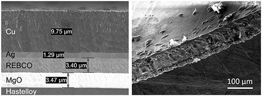
Figure 1. SEM micrographs of the THEVA tape (left) cross-section and (right) tape edge cut by the laser.
Download figure:
Standard image High-resolution image2.2. Tape bending and sample preparation
The CC tape can be bent around a circular former core in two ways, differing in the position of the REBCO layer. If the REBCO layer is positioned on the outer side of the helix (figure 2(a)), it experiences tensile bending (OUT-type configuration), while if it is positioned on the inner side of the helix (figure 2(b)), the bending is compressive (IN-type configuration).
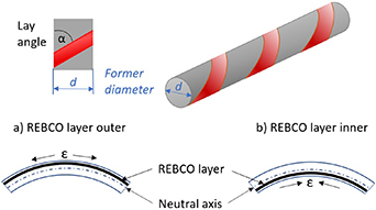
Figure 2. Illustration of the CC tape helically wound on a circular former core (rod) with the REBCO layer positioned (a) on the outer side (OUT configuration) and (b) on the inner side (IN configuration) of the helix.
Download figure:
Standard image High-resolution imageIn this work, the microstructural and superconducting properties of the REBCO CC were investigated with respect to the off-axis bending parameters, i.e. the bending configurations (IN and OUT), applying various lay angles ranging from 25° to 60° and former diameters ranging from 10 to 2 mm. In the first kind of experiments, we focused on mapping the defects formed on the REBCO layer that were caused by the tape bending. First, short pieces of CC tape (long enough to create one complete turn around the rod) were helically hand-wound around the rods with specific bending parameters. Then, the CC tape was fixed by Kapton tape on the rod and cooled in a liquid nitrogen bath for a few minutes. In the next step, from the bent section, an approximately 1 cm long sample was cut by scissors and prepared for SEM investigation (figure 3(b)). The Cu and Ag overlayers were removed from the tape by selective etching using KI3 for approximately 40 s; the process was sufficient to remove all Ag and Cu overlayers. Afterwards, the sample was rinsed with water to remove residual etchant and Ag and Cu particles. Such a process leaves the REBCO surface without any contamination or chemical damage (figure 3(c)), allowing the observation of its microstructure. For this purpose, we used the FEI quanta 250 FEG SEM.
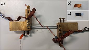
Figure 3. (a) Four-probe measurement device used for superconducting measurements. In the experiment we used a circular former core with a diameter of 4 mm and a lay angle of 60°. Image (b) shows a sample cut from the bent part of the tape and (c) shows the sample after the etching process.
Download figure:
Standard image High-resolution image2.3. Superconducting measurements
Transport DC measurements were used to investigate the impact of tape bending on its current transport properties. All the measurements were performed in a liquid nitrogen bath (77.3 K) under self-field conditions. First, the current–voltage measurements were performed on straight tape to obtain the reference value of critical current, Ic0. The critical current of the straight tape was found to be around 140–150 A, which is close to the critical current determined by the Tapestar device. Next, the tape was helically hand-wound on a circular former rod and fixed on the measurement device by the method shown in figure 3. The criterion for fixing the tape on the measurement device was to reach overall contact between the tape and the former rod without applying more force, which means that the tape is bent at the specific former diameter. The measurements were performed by keeping a constant lay angle and decreasing the former diameter step by step down from the initial 10 mm. After each measurement, the device was warmed up, the former diameter lowered by 1 mm and then inserted back into the liquid nitrogen for the next measurement. This process was repeated until the maximum tape degradation was reached. In the evaluation process, the normalised critical current Ic/Ic0 was determined, where Ic is the critical current of the tape wound at a specific bending configuration, lay angle and former diameter. From these measurements, the power-law exponent, n, of the current–voltage dependence was also determined, and compared to the reference value obtained on straight tape, n0. The power-law exponent of the straight tape was measured to be n0 = 29 ± 1.9.
3. Results and discussions
3.1. Microstructural characterisation of REBCO surface after tape bending
Figure 4 shows SEM micrographs of the reference REBCO surface and REBCO surfaces after tape bending in OUT configuration by using former diameters ranging from 10 to 3 mm, at a constant lay angle of α = 45°. The image captions also include information on the critical current degradation during the current transport measurements taken from the next chapter.
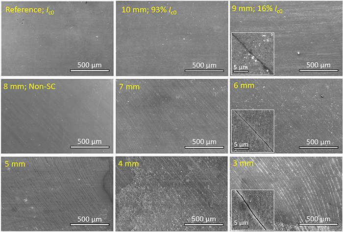
Figure 4. SEM micrographs of the reference REBCO surface and REBCO surfaces after tape bending in OUT configuration on former diameters ranging from 10 to 3 mm at a constant lay angle of α = 45°. The image captions also include information on the critical current degradation during the current transport measurements.
Download figure:
Standard image High-resolution imageAs expected, no defects on the REBCO surface were observed in the reference sample. In addition, no defects were visible after bending on the former with a 10 mm diameter. When using a diameter of 9 mm, cracks were spotted on the REBCO surface. The formation of the cracks resulted in irreversible damage to the REBCO layer. The formation of cracks in the REBCO layer after off-axis bending producing tensile stress was also reported in [15, 25–27]. As can be seen, by lowering the former diameter, the density of the cracks increased due to the higher mechanical load acting on the REBCO layer. The cracks were formed at 45° to the tape length in all cases. It was also observed that the length and the width of cracks increased when reducing the former diameter. For each sample, the concentration of cracks remained approximately constant across the width, with a small increase at the edges of the tape due to the higher axial strain acting there [22, 26, 28].
In order to investigate the mechanism of the crack creation on the REBCO layer, the tape was bent in the same OUT configuration but at different lay angles (α= 0°, 30°, 45°, 60° and 90°) and with a constant former diameter of 3 mm. Such a small former diameter was chosen to secure a high defect density and more robust data processing. Figure 5 shows the illustration of crack creation deduced from SEM micrographs in this series of samples. The SEM micrograph of the REBCO surface after tape bending using a lay angle of 45° and a former diameter of 3 mm was already shown in figure 4. As one can see, the cracks were formed predominantly in the direction parallel to the rod axis, which is indeed perpendicular to the maximum mechanical tension experienced during tape bending. In some cases, cracks with random orientation were observed, most probably caused by imperfections in the REBCO layer.

Figure 5. Illustration of the crack creation and corresponding SEM micrographs of the REBCO surfaces after tape bending in OUT configuration for different lay angles with a constant former diameter of 3 mm. White lines correspond to cracks and red squares show SEM view of the sample.
Download figure:
Standard image High-resolution imageOn the other hand, tape bending in the IN configuration, the REBCO layer showed much more persistent behaviour against defect formation. Therefore, the investigation focused on lower former diameters. Figure 6 shows SEM micrographs of the REBCO surfaces after tape bending with lay angles of α = 25°, 30°, 38°, 45°, 52° and 60° with the former diameters d = 2, 3 and 4 mm used for each lay angle. The lay angles were chosen according to parameters that make sense for the CORC/CORT cable design [3, 7, 14]. The image captions in figure 6 also include percentage information about the critical current degradation. After tape bending in the IN configuration, a delamination of the REBCO layer was observed by SEM analysis in the arrangement of the so-called 'protrusion lines' visible in figure 6 inside the red border images. The protrusion lines are the result of the delamination process of REBCO and/or MgO during compressive loading.

Figure 6. SEM micrographs of the REBCO surfaces after tape bending in IN configuration with lay angles of α = 25°, 30°, 38°, 45°, 52° and 60° and former diameters d = 2, 3 and 4 mm used for each lay angle. The image captions also include information on the critical current degradation. The SEM images in the red border contain protrusion lines, and those in the blue border contain cracks. The orange square represents the part of the REBCO surface that is zoomed in in figure 7.
Download figure:
Standard image High-resolution imageAs visible from figure 6, the highest damage, i.e. the maximum density of protrusion lines on the REBCO surface, was observed after off-axis bending using a lay angle of 60° and a former diameter of 2 mm. As expected, the lower former diameter led to higher damage on the REBCO surface at each lay angle used. This is consistent with the numerical and analytical results [22, 23, 28], showing that the axial strain increases with the lowering of the former diameter. Considering the former diameter of 2 mm, the density of protrusion lines decreased with the lowering of the lay angle until it reached 30° where the last few protrusion lines were observed on the REBCO surface, as marked with the black arrows. This trend of decreasing density of protrusion lines with the lower lay angle was also observed at the former diameters of 3 and 4 mm with the last few protrusion lines observed at lay angles of 38° and 45°, respectively.
As can be seen from the SEM images, the protrusion lines were mostly concentrated in the middle part of the tape and were almost missing at the tape edges. This non-uniform defect formation is connected with the different axial strain distribution across the tape width during tape bending: the edges are more influenced by the tensile force and the middle part of the tape is more influenced by compressive force [22, 28]. As published in [22, 28], by lowering the former diameter, the difference in axial strain between the part of the tape near the edge and the middle part of the tape is increasing. The SEM analysis indeed showed that large axial strain caused by using small lay angles and small former diameters led to the formation of cracks at the edges of the tapes, as shown in figure 6 (images inside blue border marked by white arrows) and figure 7. As can be expected, by lowering the lay angle and/or by lowering the former diameter, a higher density of cracks was formed at the tape edges, testifying that the tensile strain was increasing at the tape edges. These cracks were most probably the dominant reason for the critical current degradation of some samplesin particular, the tape bent using a lay angle of 25°, at which no protrusion lines were observed.
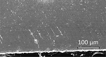
Figure 7. SEM micrograph of the cracks formed at the edges of the tape after bending in IN configuration with a lay angle of α = 25° and former diameter of 2 mm.
Download figure:
Standard image High-resolution imageAs shown in figure 6, for lay angles from 25° to 60°, the protrusion lines were always formed in a direction approximately 80° to the tape length, independently of the lay angle. This is completely dissimilar to the case of OUT bending configuration, where the cracks always follow the rod axis. Because the angles of 80° and 100° can be considered symmetrical with respect to the direction perpendicular to the tape length, the tape was additionally bent at lay angles of 70°, 90° and 110° to investigate preferential weakness symmetry (figure 8). The results showed that using a lay angle of 110° led to protrusion lines formed in the 100° direction. Using a lay angle of 70° resulted in protrusion lines being formed in the 80° direction. Using a lay angle of 90°, the protrusion lines randomly used both preferential cleavage directions. Considering this, we conclude that there are two preferential weak directions at 80° and at 100° to the tape length, respectively, marked as 1 and 2 in figure 8. Considering the fact that the protrusion lines are always formed in the same slopes independently of the lay angle used, a possible explanation could be the presence of preferential cleavage directions at approximately 80° and 100° to the tape length. Thus, this would lead to preferential orientation of defect formation instead of following the direction of lay angles at which one would expect maximum mechanical stress. This would also explain why a higher density of protrusion lines was observed when using a lay angle closer to 80°, as shown in figure 7. The formation of protrusion lines along the preferential cleavage directions could be connected with the structural weakness of the GdBa2Cu3O7−x and/or MgO buffer crystals.
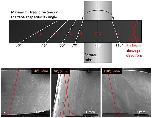
Figure 8. Maximum stress direction on the tape at specific lay angle shown with dashed white lines. There are two preferential cleavage directions in the tape, marked as 1 and 2 for lay angles 80° and 100°, respectively. The marks 1 and 2 assigned at the specific lay angles reflect which cleavage direction they prefer. The SEM images below show REBCO surfaces after tape bending with corresponding lay angles and former diameters.
Download figure:
Standard image High-resolution image3.2. Mechanical properties of the tape during bending
As the tape was bent around a specific circular surface with a given diameter and no additional force was applied, the compressive/tensile strain ( ) acting on the REBCO layer can be evaluated according to the equation

where d is the former diameter, x is the substrate thickness and t is the thickness of the overlayers [6]. The thickness of the overlayer (t) was calculated as the sum of 1 μm Ag and 10 μm Cu. The applied compressive/tensile strain on the REBCO layer was controlled entirely by us selecting the specific bending diameter. In the experiments, at both bending configurations the density of defects increased as the former diameter was lowered, reflecting an increase in the strain level that acts on the REBCO layer. As can be seen in figure 4, the cracks were visible on the REBCO layer at a diameter of 9 mm corresponding to a strain value of = 0.59% (OUT configuration). As the critical current of the tape degraded at a former diameter of 10 mm, the critical level of tensile strain is thus lower than = 0.53%,which correlates well with the fact that the REBCO layer should not exceed = 0.45%, as published in [7, 26, 28, 29]. In the IN configuration, the critical current of the tape started to degrade at a former diameter of 4 mm corresponding to a compressive strain value of = −1.31%, which is in absolute value a much higher strain acting on the REBCO layer compared to the OUT-type configuration. The REBCO CCs from different manufacturers also showed a higher critical current tolerance to applied compressive strain, as shown in [30, 31].
Figure 9 shows a schematic representation and corresponding SEM micrographs of the mechanisms of defect formation in the OUT configuration (crack formation) as well as in the IN configuration (protrusion line formation). The mechanism of crack formation is very simple: a tensile force acts on the REBCO layer until the force reaches a point when the brittle ceramic layer crashes, resulting in exceeding the fracture strength of the material and causing crack formation (figure 9(a)). Considering the compressive bending acting on the REBCO layer, we have found three general forms of protrusion lines mostly occurring as a response to energy accumulation. Figure 9(b) shows the most commonly occurring form of protrusion lines, at which the REBCO layer is broken and one part of it overlaps another. The other two forms of protrusion lines are rare but still occur on the REBCO surface. Figure 9(c) shows the form of protrusion line that is created by a broken REBCO layer where one part of it rises up with another, creating a hill-like shape. Figure 9(d) shows a form of protrusion line where the REBCO layer is broken into many small parts, which are often removed during the etching process. In some cases, a combination of these forms of protrusion lines was observed along the same line.

Figure 9. Schematic representations and corresponding SEM micrographs of the mechanisms of defect formation in (a) OUT configuration (crack formation) and in (b)–(d) IN configuration (protrusion line formation).
Download figure:
Standard image High-resolution image3.3. Superconducting properties of bent tape
The four-probe measurement method was used to perform DC transport measurements of current–voltage dependencies during the bending process. The measurements were performed in self-field conditions in a liquid nitrogen bath (77.3 K). The REBCO layer experienced both outward (OUT) and inward (IN) positions with respect to the circular former (rod) at various lay angles and diameters. The transport current measurements of the tape bent in the OUT configuration were performed only with a lay angle of 45°. The measurements performed in the IN configuration used lay angles of 25°, 30°, 38°, 45°, 52° and 60°.
Figure 10 shows the current–voltage curves of the tape bent in the OUT configuration. As can be seen, the use of the 10 mm former diameter, at which no visible cracks were observed on the REBCO surface, decreased the Ic to 93% of the reference value. By using a former diameter of 9 mm, at which cracks started to form, a significant decrease of Ic was measured, i.e. 16% of the reference value. By using a former diameter of 8 mm, the tape showed non-superconductive behaviour with a typical resistive curve, indicating that the current was flowing only through the Ag and Cu overlayers. Obviously, the cracks formed in the REBCO layer cause barriers against the current flow.
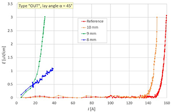
Figure 10. Current–voltage measurements of the THEVA tape bent in OUT configuration with a constant lay angle of 45° and different former diameters.
Download figure:
Standard image High-resolution imageFigure 11 shows the results of current–voltage measurements of the THEVA tape bent in IN configuration for different former diameters and lay angles. As can be seen, the critical current of the tape bent at a lay angle of 25° was not significantly changed in the range of former diameters from 10 to 6 mm. Compared to the reference measurement, the critical current of the tape decreased by lowering the former diameters to 95%, 92%, 84% and 72% for former diameters of 5, 4, 3 and 2 mm, respectively. No protrusion lines were observed on the REBCO surface when using a lay angle of 25°; however, cracks were formed at the edges of the tape, visible when using former diameters of 3 and 2 mm (figures 6 and 7).

Figure 11. Current–voltage measurements of the THEVA tape bent in IN configuration for different former diameters with a constant lay angle of (a) 25°, (b) 30°, (c) 38°, (d) 45°, (e) 52° and (f) 60°.
Download figure:
Standard image High-resolution imageWhen using a lay angle of 30°, the tape showed the best results from the point of view of the superconducting properties. The critical current of the tape was not visibly changed until the former diameter reached 4 mm. The SEM investigation showed that no visible damage on the REBCO surface was formed when using former diameters of 4 and 3 mm. With a former diameter of 2 mm, the REBCO surface contained a small number of protrusion lines and cracks at the tape edges.
The critical current of the tape bent at a lay angle of 38° decreased in correspondence to the increasing density of protrusion lines observed on the REBCO surface and visible in the corresponding SEM images (figure 6).
At the lay angles of 45°, 52° and 60°, the critical currents did not significantly change until the former diameter reached 5 mm. By using former diameters less than 5 mm, the critical currents continuously degraded until the former diameter reached 2 mm, at which point the tapes were no longer superconducting. The SEM analysis indeed showed the presence of protrusion lines on the REBCO surfaces at former diameters less than 5 mm with increasing density with the lowering of the former diameters.
Figure 12 shows the dependence of the normalised critical current Ic
/Ic0 vs the former diameter d (a), Ic
/Ic0 vs strain (b), normalised power-law exponent n/n0 vs d (c), and n/n0 vs (d) measured on THEVA tape that was bent in the IN and OUT configurations for different lay angles with data taken from the previous plots. As shown from figure 12, the power-law exponent n followed the critical current Ic behaviour of the tapes during the bending process in all cases. This behaviour of the superconducting properties of the bent tapes was also observed in other studies [15, 32]. The critical current and power-law exponent of the tape tolerated bending in the IN configuration at much lower former diameters, i.e. with higher strains acting on the REBCO layer compared to the bending in the OUT configuration. It can be said that if the THEVA tape is bent in the OUT configuration, the cracks are formed in the REBCO layer at relatively high former diameters; thus, it is not recommended to design a round cable with such an arrangement of tapes.

Figure 12. Dependence of normalised critical current Ic/Ic0 vs former diameter d (a), Ic/Ic0 vs strain (b), normalised power-law exponent n/n0 vs d (c), and n/n0 vs (d) measured on THEVA tape that was bent in IN and OUT configurations with different lay angles.
Download figure:
Standard image High-resolution imageConsidering results shown in figure 12, a suitable configuration for a round cable made from the THEVA tape we used in our study is IN configuration, i.e. the configuration that causes compressive strain in the REBCO layer. A lay angle of around 30° was found to be optimal from the point of view of critical current retention, as shown in figure 13, in agreement with the lowest level of damage visible on the REBCO surface in the SEM analysis (figure 6). When using lay angles higher than 30°, the critical current and the power-law exponent started to degrade sooner, i.e. at higher diameters and with lower strain acting on the REBCO layers. The SEM analysis indeed showed that the number of protrusion lines was increased with lay angles higher than 30° with the consequence of critical current degradation. By using a lay angle lower than 30°, the current transport properties degraded earlier (at higher former diameters), although no protrusion lines were observed on the REBCO surface, but the formation of cracks at the tape edges became responsible for the critical current degradation.

Figure 13. Dependence of normalised critical current Ic/Ic0 vs lay angle α (top) and normalised power-law exponent n/n0 vs α (bottom) measured on the THEVA tape bent in IN configuration with different former diameters.
Download figure:
Standard image High-resolution image
Unlike in the studies working with different tapes [22, 28, 33], where a lay angle of 45° was found to be the optimal angle for superconductivity persistence, in the THEVA tape a lay angle of around 30° was found to be the best choice with the lowest level of defects formed in the REBCO layer and minimal degradation of the critical current. In general, the tape bending in the IN type configuration causes damage in the REBCO layer in the form of protrusion lines that do not cause such significant obstacles against the current flowing as the cracks do. However, any damage in the REBCO layer, regardless of its size, could degrade the ability of the tape to carry current due to excessive local dissipation. Finally, in both bending configurations (IN and OUT), the degradation of the critical current and power-law exponent correlates well with the number of defects visible on the REBCO layer.
4. Conclusions
In this work, the change in the microstructural and superconducting properties of GdBa2Cu3O7−x CC was systematically studied with respect to the off-axis bending parameters. The superconducting layer was positioned on the outer side (OUT configuration) as well as on the inner side (IN configuration) of the helix at various lay angles and former diameters. The microstructural characteristics of the REBCO surface were assessed using SEM analysis. Prior to the SEM analysis, the Cu and Ag overlayers were etched away from the bent part of the tape allowing direct inspection of the REBCO surface. A four-probe measurement method was used to investigate the influence of the bending parameters on the current transport properties.
Considering tape bending in the OUT configuration, the cracks on the REBCO surface were visible in the SEM analysis of tapes bent at a former diameter of 9 mm and lay angle of 45°. The critical current of the tape started to degrade when using a former diameter of 10 mm. The investigation showed that the cracks are formed in parallel to the rod axis.
The measurements of the tape bent in the IN configuration were taken considering a series of lay angles; in particular, 25°, 30°, 38°, 45°, 52° and 60°. The highest critical current retention and also the lowest damage on the REBCO layer were observed when using a lay angle of 30°. In particular, the critical current considerably degraded at a diameter of 3 mm, and defects were visible on the REBCO surface at a diameter of 2 mm. When using lay angles higher than 30°, the critical current degraded sooner (at higher diameters), and a higher density of defects in the form of protrusion lines was observed on the REBCO surface. The protrusion lines are the result of the delamination process of the REBCO and/or MgO during compressive loading. By using a lay angle lower than 30°, the critical current degraded sooner. No protrusion lines were observed on the REBCO surface, but the formation of cracks at the tape edges was responsible for the earlier critical current degradation. We found that the protrusion lines are formed at approximately 80° to the tape length, independently of the lay angle, following a preferential cleavage direction. We found that the protrusion lines are also formed at 100° after tape bending by using lay angles higher than 100°, reflecting preferential weakness symmetry.
In both bending configurations (IN and OUT), the lower former diameters led to a higher density of defects formed on the REBCO surfaces. The degradation of current transport properties correlates well with the number of defects formed in the REBCO layer.
Acknowledgments
This work was supported by the grant agency VEGA under contract 1/0205/21, and by the contract APVV-20-0056. It was co-funded by EUREKA member countries and the European Union in the Eurostars-2 project E! 115264 FILAMENTS4FUSION.
Data availability statement
All data that support the findings of this study are included within the article (and any supplementary files).