
Abstract
Characterized by their very low rotational drag, applications of high-temperature superconductor (HTS) bearings have been expanded in some high-precision instruments. We have developed a sensitive magnetic suspension stand based on an Evershed-type hybrid HTS bearing to measure μN-level thrust. The hybrid HTS bearing uses the strong attractive force of a permanent magnet (PM)-biased bearing to support the main load in the bearing, while instability in the PM-biased bearing is compensated by the magnetic stability from a HTS bearing. Compared with a single PM/HTS bearing, the hybrid HTS bearing is intended not only to support larger loads but also to suppress rotation loss and levitation drift. Loading capacity, loss and damping torque were explored for different design parameters such as bearing gaps L1, L2 and the field cooling height (FCH) of bulk HTSs. Spin-down testing suggested that the loss of a hybrid HTS bearing can be reduced by increasing the HTS bearing gap L2 or reducing the FCH. The hybrid HTS bearing showed a typical oscillation behavior at extreme low frequencies, and torsional pendulum testing suggested that the spring constant k of the hybrid HTS bearing can be as low as 36.39 μN m deg–1. A micro-thrust stand based on the hybrid HTS bearing was established to test an electrospray thruster in a vacuum chamber, and the measurement result of 26.61 μN shows the ability of the micro-thrust stand to achieve μN level testing.
Export citation and abstract BibTeX RIS

Original content from this work may be used under the terms of the Creative Commons Attribution 4.0 license. Any further distribution of this work must maintain attribution to the author(s) and the title of the work, journal citation and DOI.
1. Introduction
Benefiting from self-stable suspension and moderate stiffness in the radial and axial directions, bulk high-temperature superconductors (HTS) have many engineering applications, such as maglev trains [1, 2], superconducting bearings [3, 4], flywheel energy storage (FES) systems [5, 6] and high-resolution devices [7, 8]. In addition, extensive advances have been made in understanding and reducing rotational losses in HTS magnetic bearings, especially for application in FES systems with a high rotation speed [9, 10].
In recent years, hybrid superconducting magnetic bearings have been widely studied to realize both larger suspension stiffness and better rotational stability at high frequencies. In general, an electromagnetic (EM) bearing or a permanent magnet (PM) bearing is combined with a HTS bearing to construct a hybrid bearing. With a strong attractive force in the EM or PM bearing, the loading capacity can be greatly increased in the hybrid bearing. McMichael et al designed a hybrid superconducting bearing [11] with a load capacity greater than 41 N cm−2 at 77 K. A fully passive HTS magnetic bearing with an Evershed-type structure achieved an energy loss of less than 5% per hour at a speed of 2000 rpm with a load of 19 kg [12]. A mixed-μ hybrid superconducting bearing proposed by Hull et al was tested; the friction coefficient was less than 10−6 for a bearing speed of 100 m s−1 and the coefficient was at the level of 3 × 10⁻⁸ for speeds lower than 5 m s−1 [13]. Furthermore, Rastogi et al applied a special Evershed-type HTS composite bearing comprising axial and journal bearings in a HTS flywheel system [14] to effectively suppress the wobbling of the rotor and reduce the rotation loss by an order of magnitude.
Due to their very low rotational drag, applications of HTS bearings have been expanded in some high-precision instruments including accelerometers [15], lunar telescopes [16], sensitive gravimeters [17], polarimeters [18] and micro-force sensing devices [7, 10]. The use of HTS magnetic bearings in building a micro-thrust test stand is a relatively new application. Conventionally, different kinds of mechanical micro-thrust stands, such as hanging pendulums [19], inverted pendulums [20] and torsion pendulum balances [21], have been developed to measure mN thrust for micro-thrusters. However, these mechanical test stands face difficulties such as complex mechanical structures, low loading capacity and deflection tares from service lines.
Compared with mechanical stands, magnetic suspension test stands are believed to show low interference and are able to perform attitude control testing for micro-thrusters and associated micro-satellites. Hicks et al designed an active EM stand to measure a thrust magnitude of 6.9 µN with an uncertainty of 0.35 µN for an electrospray thruster [22]. Busek Co. Inc. developed an EM test stand for a colloid thruster applied in the LISA Pathfinder mission to obtain thrust in the range in 5–30 µN and thrust noise lower than 0.1 µN Hz–1/2 [23]. A torsional pendulum thrust stand based on a single PM/HTS bearing was designed by Fawzi et al to measure a 25.2 µN thrust with an error of 1.78 µN [24], and the HTS bearing provided strong suspension without the participation of active control.
However, some deficiencies also occur in single PM/HTS bearings applied in micro-thrust measurement, such as a large moment of inertia and levitation drift of the bearing, and tilting of the bearing shaft. Furthermore, these deficiencies cause a low-frequency whirling motion and non-linear drag of the bearing, and restrict the resolution of the micro-thrust test stand [25].
In this paper, an Evershed-type hybrid HTS bearing is proposed to replace the single PM/HTS bearing in building a micro-thrust test stand. The characteristics of two gaps, the PM bearing gap and HTS bearing gap, in the Evershed-type bearing are investigated to show the effect of the two gaps on the loading capacity, rotation loss and resolution of the micro-thrust stand. We also discuss the influence of field cooling height (FCH) and rotation frequency on the loss properties of the hybrid HTS bearing. Furthermore, the micro-thrust stand based on the hybrid HTS bearing was tested in a vacuum to ascertain the thrust of an electrospray thruster designed by our group.
2. Principle and design of the Evershed-type hybrid HTS bearing
2.1. Bearing design and its axial force model
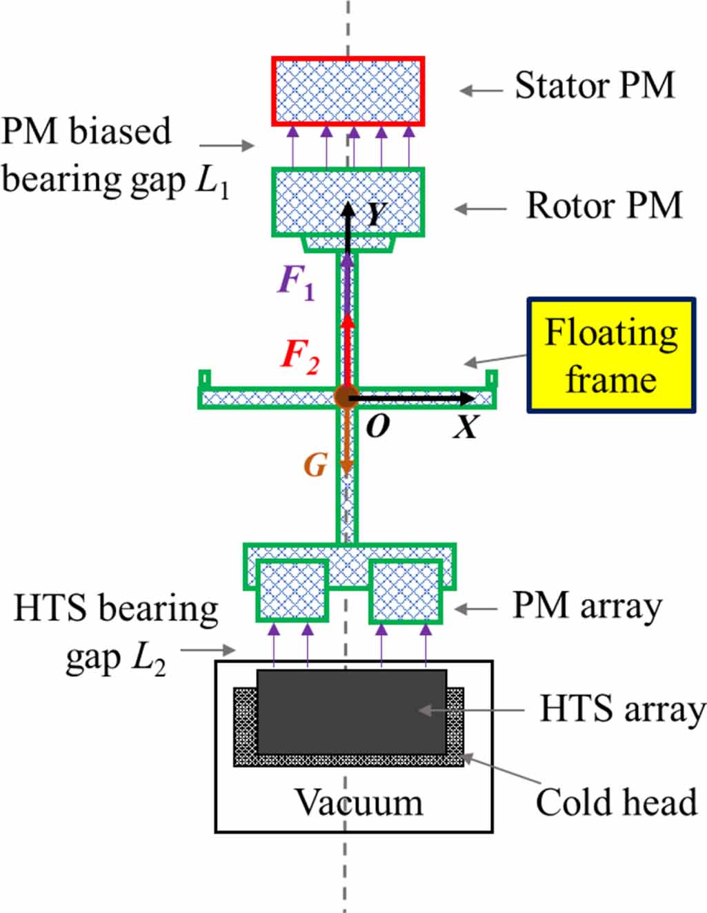
Figure 1 shows a sketch map of the Evershed-type hybrid HTS bearing used for micro-thrust measurements, including a PM-biased bearing and a HTS bearing.

Figure 1. Schematic map of the Evershed-type hybrid HTS bearing.
Download figure:
Standard image High-resolution imageThe PM-biased bearing composed of a stator PM and a rotor PM will bear more than 80% of the mass for the hybrid bearing. The two PMs made of NdFeB material are cylindrical in shape. The surface magnetic strength of the stator PM with a diameter of 25 mm and a height of 15 mm is 352 mT, while the surface magnetic strength of the rotor PM with a diameter of 20 mm and a height of 10 mm is 188 mT. The axial attraction force F1 between the two PMs was tested and is shown in figure 2; the absolute attraction force has a range of 0–50 N when the air gap L1 of the PM-biased bearing changes from 30 to 0 mm.
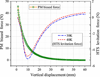
Figure 2. Axial force behaviors in the PM-biased bearing and the HTS bearing.
Download figure:
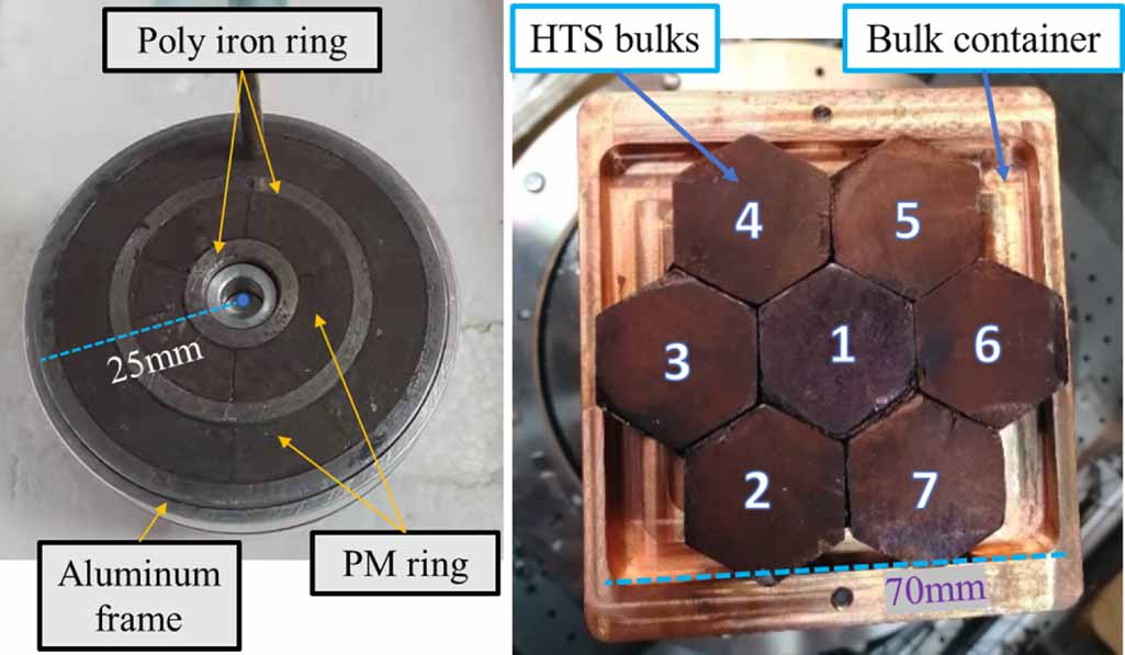
Standard image High-resolution imageThe HTS bearing composed of a PM array and a HTS array is shown in figure 3. The PM array is made of two PM rings with opposite polarity and three iron rings to obtain a maximum axial magnetic field strength of 500 mT on the surface of the middle iron ring. The HTS array consists of seven hexagonal HTS bulks with a diameter of 30 mm and a height of 16 mm, and these bulks are held in a copper sample holder connected to second cold head cooled by a helium refrigerator. Figure 2 also shows the experimental data for the axial force F2 in a HTS bearing with a FCH of 3 mm.

Figure 3. PM array (left) and HTS array (right).
Download figure:
Standard image High-resolution imageThe hybrid HTS bearing is constructed to provide the loading capacity for a floating frame, which is closely related to the PM-biased bearing gap L1 and the HTS bearing gap L2. The attractive force F1 increases as L1 gradually decreases, and the repulsive force F2 in the HTS bearing decreases with increase the air gap L2. Finally, the floating frame will be suspended at some position to keep the balance between bearing forces and gravity.
However, stable suspension of the floating frame depends on the total stiffness of the hybrid HTS bearing. The bearing can be stable only when the total stiffness is no greater than 0 [26], that is the stiffness of the PM-biased bearing is less than that of the HTS bearing, as shown in the following formula (1):
2.2. Models of rotation loss in the hybrid HTS bearing
Rotation loss is an important indication for an Evershed-type hybrid HTS bearing; it determines the energy efficiency of the bearing applied in flywheel systems and the resolution of rotational instruments.
The rotation losses in the hybrid HTS bearing mainly come from eddy current loss and hysteresis loss [27, 28]. As shown in equation (2), the first part is the eddy current loss, which has a direct relation to the rotation speed v, and the second part is the hysteresis loss, which is mainly determined by ΔB and Jc
Here, K2 is the proportionality coefficient, K1 is a geometry factor, ΔB is the circumferential fluctuation of the PM magnetic field, v is the rotation speed, Jc is the critical current density in the superconductor and P is the total power loss.
In low-frequency applications of the hybrid HTS bearing, the eddy current loss can be greatly reduced and even ignored, and the hysteresis loss possibly plays a prominent role in the hybrid bearing. In our design, the PM array is spliced by arc-shaped magnets, which leads to inevitable circumferential fluctuation of the magnetic field. Specifically, the circumferential magnetic field distribution of the PM array was scanned using a Gauss meter, and the results for ΔB varied between 1 mT and 100 mT when the measuring gap was changed from 5 mm to 1 mm. Therefore, an effective method for reducing the effect of the circumferential inhomogeneity ΔB on the hysteresis loss of the hybrid HTS bearing is to increase the HTS bearing gap L2.
3. Experimental setup and testing methods for the rotational properties of the hybrid HTS bearing
3.1. Experimental setup
Loading and loss characteristics were investigated in an experimental setup comprising the hybrid HTS bearing, as shown in figure 4. The experimental setup mainly includes a vertical displacement adjuster, the PM-biased bearing, the HTS bearing, a two-stage refrigerator, a vacuum hood served by a molecular pump, support columns and a ground optical table.
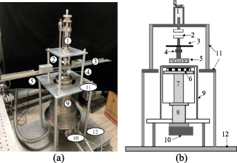
Figure 4. (a) Photo of the experimental setup. (b) Schematic view of the experimental setup. Components of the setup are as follows: (1) vertical displacement adjuster, (2) PM-biased bearing, (3) floating frame, (4) Archimedes block, (5) PM array, (6) HTS bulk array, (7) secondary cold head, (8) primary cold head, (9) vacuum hood with thin wall, (10) molecular pump, (11) support columns, (12) ground optical table.
Download figure:
Standard image High-resolution imageThe vertical displacement adjuster connects to the stator PM and adjusts the gap L1 in a range of 100 mm with an accuracy of 0.01 mm. Superconducting bulks are cooled by the two-stage refrigerator in a wide temperature range of 4.2 K–80 K with a resolution of 0.1 K. The levitation gap L2 of the HTS bearing has a minimum value of 3 mm due to limitation by the vacuum insulation and the top wall thickness of the vacuum hood.
3.2. Testing method for bearing rotation loss
In the experimental setup, the rotational behavior of the hybrid HTS bearing is measured by a special rotation displacement method using a charge-coupled device (CCD) laser sensor and an Archimedes block axially joined to the floating frame, as shown in figures 4 and 5. Figure 5 shows the design and size of the Archimedes block, which provides rotational displacement from a minimum value of 15 mm to a maximum value of 21 mm with a resolution of 3 μm when the resolution of the CCD laser sensor is 1 μm.
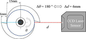
Figure 5. Rotational displacement method dependent on a CCD laser sensor and an Archimedes block.
Download figure:
Standard image High-resolution imageThe rotational displacement method can output the circumferential positions and angles of the hybrid HTS bearing and then obtain the rotational speed by a differential calculation. Figure 6 shows a typical curve measured by the rotational displacement method; the bearing gives 11 cycles of rotation in the first 5 s.
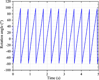
Figure 6. Rotation angle of the Archimedes block in the first 5 s.
Download figure:
Standard image High-resolution image4. Experimental results and discussion
4.1. Loading characteristics of the hybrid HTS bearing
In order to present the loading characteristics of the hybrid HTS bearing for different values of gaps L1 and L2, we performed two groups of loading testing in the experimental setup: the HTS bearing works with a FCH of 8 mm and the HTS bulks are cooled to a temperature of 30 K. The detailed results are listed in table 1.
Table 1. Loading results for the Evershed-type bearing.
| Mass (kg) | L1 (mm) | PM bearing force | Loading ratio | L2 (mm) | HTS bearing force | Loading ratio |
|---|---|---|---|---|---|---|
| 2.092 | 20 | 4.8 N | 23.4% | 5.5 | 15.7 N | 76.6% |
| 15 | 6.2 N | 30.2% | 6 | 14.3 N | 69.8% | |
| 10 | 12.5 N | 60.9% | 7 | 8.0 N | 39.1% | |
| 5 | 25 N | 121.9% | 9.5 | −4.5 N | −21.9% | |
| 4.092 | 20 | 4.8 N | 12.0% | 3.5 | 35.3 N | 88.0% |
| 15 | 6.2 N | 15.5% | 4 | 33.9 N | 84.5% | |
| 10 | 12.5 N | 31.2% | 5 | 27.6 N | 68.8% | |
| 5 | 25 N | 62.3% | 7 | 15.1 N | 37.7% | |
| 1.5 | 43.3 N | 108.0% | 8.5 | −3.2 N | −8.0% |
For an overall mass of the floating frame of 2.092 kg, when the gap L1 is decreased from 20 mm to 5 mm, the attraction force in the PM-biased bearing increases to provide a larger loading ratio while the loading ratio of the HTS bearing shows a continuous drop, up to −21.9%. This suggests that the hybrid HTS bearing can provide stable levitation even when the loading ratio given by the PM-biased bearing is greater than 100%. As a result, the air gap L2 in the HTS bearing increases from 5.5 mm to 9.5 mm.
When the overall mass of the floating frame is 4.092 kg, the same adjustments in the two gaps were completed to show the change in loading ratios with the hybrid HTS bearing. Compared with the mass of 2.092 kg, a mass of 4.092 kg allows the PM-biased bearing to work at smaller gap L1 of 1.5 mm without losing the suspension state of the bearings.
4.2. Rotational loss characteristics at low frequency
Depending on the rotational displacement method, the experimental setup can be used for typical spin-down testing to evaluate the rotational loss characteristics of the hybrid HTS bearing. With a FCH of 8 mm and a cooling temperature of 30 K, the 2.092 kg floating frame is excited along the tangential direction by a cold air gun to a rotation speed close to 7 rad s−1, then the process of decay of the rotation speed at different bearing gaps L2 is recorded (see figure 7).

Figure 7. Decay of the rotation speed of the hybrid HTS bearing for different bearing gaps L2.
Download figure:
Standard image High-resolution imageCorresponding to different gap L2 conditions, the decay behavior of the rotation speed indicates the presence of a rotational friction torque. Figure 7 shows that the rotation speed does not decay linearly, and the absolute slopes of the decay curves decrease gradually, showing that rotational friction torque decreases with time.
Furthermore, it can be concluded that with increase in L2, the speed of decay becomes slower, meaning that the rotational friction torque decreases with increase in the air gap L2. Formula (3) shows that the rotational friction torque Mf can be calculated by multiplying the inertia moment I by the angular acceleration α obtained by the fitting of the decay curve

In order to further analyze the effect of the HTS bearing gap L2 on rotational friction torque Mf, we prepared a test with a different FCH of 12 mm. The same spin-down test was performed for the three bearing gaps L2 of 5.5 mm, 7 mm and 9.5 mm, respectively. In the decay curves, we extracted the typical values of these curve slopes to calculate the rotational friction torque in three speed ranges, which were 5–6.5 rad s−1, 3–4 rad s−1 and 2–2.5 rad s−1.
Comparisons of the rotational friction torques for different FCHs, air gaps L2 and speed ranges are shown in figure 8. It can be seen that the friction torque decreases with increase in the air gap L2 for both FCHs. From table 1, the air gap L1 will be continuously reduced as air gap L2 increases to provide a larger loading ratio. However, the reduction of the air gap L1 did not obviously lead to increased loss in the PM-biased bearing, and decrease of the whole rotational friction torque with increase in the air gap L2 indicates that rotation loss in the HTS bearing plays a prominent role in the hybrid HTS bearing.
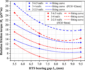
Figure 8. Rotational friction torque Mf for different FCHs.
Download figure:
Standard image High-resolution imageThe second phenomenon from figure 8 is that a larger FCH leads to larger friction torque. It can be understood that, for the same L2, a larger FCH means a greater vertical drop of the HTS bearing, and then larger induced currents are produced in the bulk superconductors. Further, a larger induced current and flux penetrations result in larger hysteresis loss in the bulks.
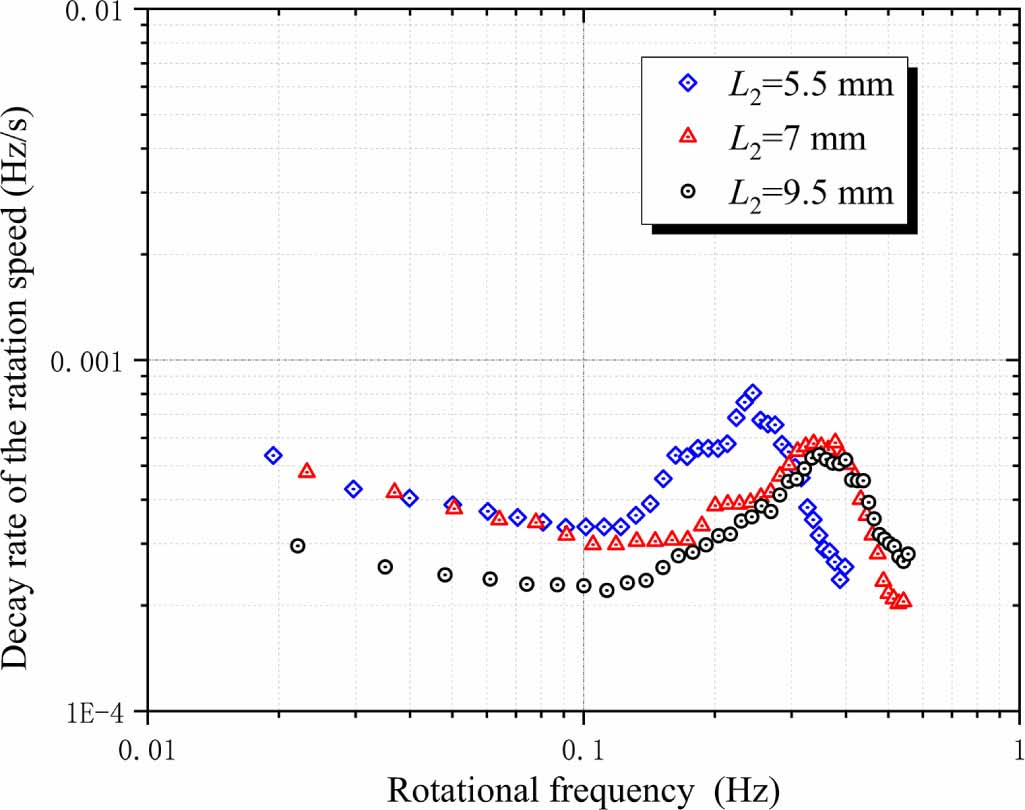
To show the effect of air gap L2 on the rotation decay rate in the frequency range lower than 1 Hz, the curve data in figure 7 are differentiated and given in fast Fourier transform, as shown in figure 9. It can be seen that with a decrease in the rotational frequency, the rotation decay rate shows a small spike from 0.6 Hz to 0.1 Hz; this drop ends with a very slow increase below 0.1 Hz. The small spike can be explained by the possible effect of wobbling rotation for low bearing frequencies. Compared with the testing data in the frequency range lower than 1 Hz given by Cansiz et al [25], the spike value of the rotation decay rate in figure 9 seems smaller, presenting the possible benefit of the hybrid HTS bearing using double bearings to provide the better axial stability and resist wobbling rotation and associated loss.
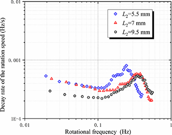
Figure 9. Rotation decay rate in the frequency range lower than 1 Hz corresponding to different air gap L2.
Download figure:
Standard image High-resolution imageFigure 9 also shows more clearly that the rotation decay rate can have a smaller value for a larger air gap L2. Because the hysteresis loss of the HTS bearing plays a more important role in the low-frequency range, a larger L2 leads to a smaller effect of circumferential field fluctuation on the hysteresis loss, causing a reduction in the rotation decay rate.
4.3. Torsional pendulum characteristics at low frequencies
With continuous decrease in the rotation frequency, the floating frame using the hybrid HTS bearing will enter a new rotational state. In the state below 0.02 Hz, a single rotation cycle cannot be finished, and the rotation swings around a special position to show an oscillatory behavior that usually happens in a typical second-order system. We name this behavior torsional pendulum suspension for the floating frame, and the oscillation curves corresponding to different FCHs are shown in figure 10.
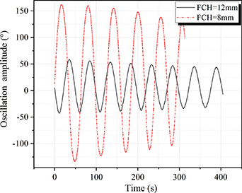
Figure 10. Torsional oscillation curves corresponding to different FCHs.
Download figure:
Standard image High-resolution imageThe torsional oscillation of the hybrid HTS bearing was studied when working at different FCHs and air gaps L2. The torsional oscillation was analyzed using a log decrement method [29], and the sequence shown in figure 11 was used to calculate dynamic parameters of the torsional oscillation, such as period T, damping ratio ζ, natural frequency ωn, spring constant k and damping coefficient c. These calculated values related to torsional oscillation for FCH values of 8 mm and 12 mm are listed in table 2.
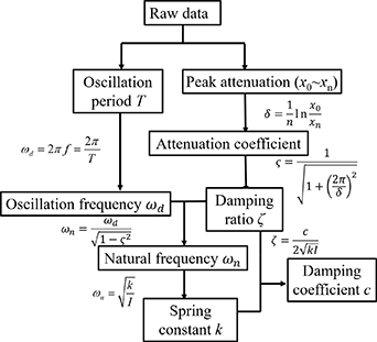
Figure 11. Calculation of torsional parameters by the log decrement method.
Download figure:
Standard image High-resolution imageTable 2. Torsional characteristics for different FCHs.
| Parameters | FCH = 8 mm (at 30 K) | FCH = 12 mm (at 30 K) | ||
|---|---|---|---|---|
| PM bearing gap L1 | 20 mm | 10 mm | 25 mm | 12 mm |
| HTS bearing gap L2 | 5.5 mm | 7 mm | 5.5 mm | 7 mm |
| Period T (s) | 47 | 54 | 48 | 50 |
| Damping coefficient c (μN m/ (ms−1)) | 5.215 | 2.375 | 2.808 | 1.583 |
| Damping ratio ζ | 0.0095 | 0.0054 | 0.0056 | 0.0028 |
| Spring constant k (μN m deg–1) | 48.03 | 36.39 | 46.05 | 42.44 |
From table 2, both the spring constant k and damping ratio ζ of the torsional floating frame decrease with increase in the air gap L2. The decrease in the damping ratio ζ occurs for the same reason that a larger air gap L2 causes smaller hysteresis loss in torsional oscillation. The decrease in the spring constant k occurs because the decrease in the air gap L1 from 20 mm to 10 mm confers better axial stability on the PM-biased bearing, reducing the influence of the gravity potential well on the restoring moment to the torsional oscillation. A smaller spring constant k also indicates that the floating frame will have a higher resolution when it is subject to the same applied force along the tangential direction.
Table 2 also shows that a larger FCH leads to a smaller damping coefficient c, suggesting the same effect of the FCH on the hysteresis loss. Compared with a FCH of 12 mm, the FCH of 8 mm uses a smaller air gap L1 and provides better axial stability; then better axial stability determines a smaller spring constant k. Therefore, the PM-biased bearing plays an important role in determining the spring constant of the floating frame during torsional oscillation.
4.4. Micro-thrust measurements based on the torsional pendulum characteristics of the hybrid HTS bearing
A micro-thrust stand based on the hybrid HTS bearing was designed and established to measure the micro-thrust for an electrospray thruster designed by our group. The thruster has a designed value of thrust of about 30 μN with an extraction beam current of 200 μA under an extraction voltage of 2500 V. Detailed information about the thruster can be found in the literature [30].
Figure 12 shows that the thruster is attached at one end of the floating frame, and the counterweight is placed at the other end to maintain the balance of the floating frame. The thrust stand works in a vacuum chamber, and the HTS bearing is served by a two-stage refrigerator.
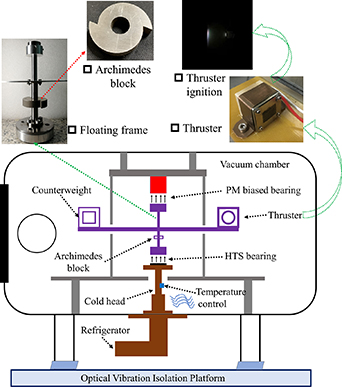
Figure 12. Schematic diagram and image of the micro-thrust stand based on a hybrid HTS bearing.
Download figure:
Standard image High-resolution imageThe same experimental method described in section 4.3 was used to test the torsional characteristics of the micro-thrust stand. In this setup of the stand for micro-thrust measurement we used the same working condition as that shown in second column of table 2 (a FCH of 8 mm, bulk cooling temperature of 30 K, air gap L2 of 7 mm).
In calibration of the micro-thrust stand, subject to the impact of the micro-thrust on the floating frame in the tangential direction, the natural properties of the micro-thrust stand, such as the natural frequency ωn, spring constant k and damping ratio ζ, can be calculated by the log decrement method. After several repeated calibrations, the average value of the spring constant k is obtained as 39.91 μN m deg–1, which is close to the value of k shown in table 2.
For a small range of oscillation angle, the thrust has a linear relation with the oscillation angle. When we measure the change of oscillation angle θ, the micro-thrust can be calculated from equation (4)

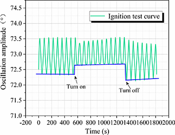
The electrospray thruster was ignited at 600 s and stopped at 1300 s. The change in oscillation angle of the stand was recorded and is shown in figure 13. The stand showed a quick and stable response to thruster ignition. A small change in the oscillation angle amplitude of 0.3° occurred when the thruster was turned on. For a thrust arm length of 450 mm, the thrust of the thruster in this ignition is calculated to be 26.61 μN, which is close to the designed value.
Figure 13. Change of oscillation angle after ignition of the electrospray thruster.
Download figure:
Standard image High-resolution image
5. Conclusion
This paper has provided preliminary results for exploring the use of Evershed-type hybrid HTS bearings in micro-thrust measurements. The effect of two air gaps on loading capacity, rotation loss and torsional pendulum characteristics was investigated. Thanks to the PM-biased bearing, the hybrid HTS bearing provided a larger loading capacity than a single PM/HTS bearing. On the other hand, spin-down testing of the hybrid HTS bearing showed that the rotational friction torque and torsional oscillation damping of the hybrid HTS bearing also decrease with increase in the HTS bearing gap L2, demonstrating the better axial stability of the hybrid HTS bearing. A micro-thrust stand based on the hybrid HTS bearing was established in a vacuum to test the electrospray thruster, and the experimental value of 26.61 μN indicates successful application of the hybrid HTS bearing in micro-thrust measurement with resolution at the μN level.
Acknowledgments
This work was financially supported by the National Natural Science Foundation of China (No. 11772025).
Data availability statement
The data that support the findings of this study are available upon reasonable request from the authors.