
Abstract
A wind and react (W&R) coil of inner diameter 53 mm has been made from multi-core MgB2/Nb/CuNi wire manufactured by the internal magnesium diffusion (IMD) process. The W&R coil is wound from non-insulated rectangular wire of 1 mm2 with only 5 µm thick stainless steel foil used for interlayer insulation. The transport current performance of the coil and short wire samples was measured in a liquid He bath at external magnetic fields of 4.5–8.5 T and also in self-field conditions in sub-cooled water ice at temperatures between 33 K and 38 K. The presented MgB2 coil exhibits stable behavior at water ice cooling, and its high space factor allows a high current density of winding in comparison to the data from the already published MgB2 coils. The presented results demonstrate that MgB2 windings can be used safely in He-free conditions inside sub-cooled water ice, and this technique can be further optimized and used for future MgB2 coils.
Export citation and abstract BibTeX RIS

Original content from this work may be used under the terms of the Creative Commons Attribution 4.0 license. Any further distribution of this work must maintain attribution to the author(s) and the title of the work, journal citation and DOI.
1. Introduction
It has been shown in many experiments that MgB2 wires made by the internal magnesium diffusion (IMD) process demonstrate considerably higher current densities than those obtained by the powder-in-tube (PIT) method [1–7]. This is predominantly due to the improved grain connectivity of the MgB2 phase with negligible content of MgO created by the IMD process [8]. Until now, many MgB2 coils using PIT MgB2 wires have been successfully made and tested [9–13]. Most of these coils were wound from already annealed MgB2 wires using the react and wind (R&W) technique, in which the space factor (SF = total conductor turns area/winding space area) is typically between 0.7 and 0.8. The coil's critical current properties already show good potential for building low-field MRI systems [10–13]. However, the R&W technique limits the required tension and bending strains applied to the wire necessary for a moderate pre-compression of winding. Due to the high brittleness of MgB2 filaments [14–16], the R&W technique cannot be used for the manufacture of small-diameter coils, and therefore the wind and react (W&R) technique should be applied [17]. On the other hand, a more complicated coil former design and high-temperature wire insulation are needed for W&R. For example, mica tape or S-glass wrap or braid insulation is usually applied for W&R coils [4, 17]. Such insulation thickness is typically around 100 μm and it results in a low space factor of superconducting winding. Recently, Wang et al fabricated and successfully tested W&R MgB2 coils of 38 mm inner diameter with mica tape insulation wound from six-filament MgB2 wire by the IMD process [4]. While a low space factor (SF ∼ 0.35) was obtained for the coil insulated by mica tape [4], an increased one was presented by Kim et al with a partially insulated coil (by S-glass layer-to-layer insulation) [18]. Kim et al used six-filament Cr-coated 0.98 mm wire for a W&R coil of inner diameter 52.74 mm with SF ∼ 0.41 due to a ∼0.12 mm thick S-glass sheet used for interlayer insulation [18]. Watanabe et al successfully presented a W&R MgB2 coil made of ten-filament Monel-sheathed MgB2 and ∼70 µm thick T-glass cloth insulated wire (0.83/0.69 mm) aimed at Klystron applications [19]. This coil with Cu interlayer foils (with SF ∼ 0.304) consumed stored energy by itself without a special quench protection system. An extremely high SF > 0.90 was reached recently for a W&R MgB2 coil of 53 mm with 15 µm thick Al2O3 layer insulation [20]. Such high SF can be obtained due to the application of rectangular MgB2 wire with Al outer sheath self-insulated by anodic oxidation. Many non-insulated superconducting coils have been reported during the last ten years, and even coils impregnated by conductive solder have been proposed [21]. Compared with insulated coils, non-insulated ones have higher thermal stability, better self-protection and better quench recovery capability [21–23]. However, non-insulated coils have weaknesses such as magnetic field saturation and charge–discharge delay. In particular, charge–discharge delay is a significant obstacle for superconducting magnetic energy storage due to the frequency variable current operation. Recently, Bykovskiy et al made fully soldered coil windings of non-insulated turns using NbTi/Cu wire with CuNi cladding of 1 mm diameter, which show superior mechanical properties [24]. The apparently enhanced stability of these coils avoids the need for any training, requires no quench protection system and enables the coils to be operated up to the short-sample critical current [24]. On the other hand, non-insulated coils are not suitable for AC or pulse operations due to the significantly high AC losses caused by inter-turn coupling. A quasi-insulated coil can partially compensate for the disadvantages mentioned above [21].
In this study, a W&R coil was made from non-insulated six-filament rectangular MgB2/Nb/CuNi wire and measured at liquid He and water ice cooling conditions. The coil's performance is compared with the data obtained on short wire samples and also with the published data for several MgB2 coils.
2. Experimental details
2.1. MgB2 wire
IMD MgB2 wire was prepared using a magnesium rod of 3.16 mm (99.93%) inserted into a Nb tube of 6.25/7.85 mm and filled with amorphous boron powders (99.80% purity and particle size below 1 µm). The assembled Mg/B/Nb composite was groove-rolled down to ∼2.6 mm and then rotary-swaged into circular wire of 2.62 mm in diameter. The wire was then annealed at 280 °C/30 min, divided into six pieces and inserted into a CuNi30 tube of 8/10 mm (annealed at 250 °C/30 min) together with a Cu central wire of purity 4N5. The assembled composite was then deformed by rotary-swaging to a diameter of 9.0 mm followed by groove-rolling up to a final size of 1.07 mm by ∼10% per pass area reduction. Short wire samples were finally heat-treated at temperatures 645 °C–655 °C with durations of 25 min. Figure 1 shows the cross-section of heat-treated six-filament MgB2/Nb/CuNi rectangular wire with an area of 1 mm2 containing 15.9% of MgB2, 23.6% of Nb and 42% of CuNi30 and 7% of central Cu. The inner filament's holes take up 11.5% of the whole wire area.

Figure 1. The cross-section of six-filament MgB2/Nb/CuNi wire heat-treated at 655 °C/25 min.
Download figure:
Standard image High-resolution image2.2. MgB2 coil
Around 11 m long MgB2/Nb/CuNi30 non-annealed wire was used for coil wound on the stainless steel (SS) former shown in figure 2(a). SS foil of thickness 5 μm was used as interlayer insulation for the winding, having a total of 58 turns wound in four layers; see figure 2(b). The pull-back force of the take-off reel was around 30 N to achieve tight turn-to-turn fitting of the wire and a moderate circumferential pre-compression of the winding. The heat treatment profile was first optimized for the same size coil wound from rectangular Cu wire of 1 × 1 mm2 with two thermocouples, which showed that more than 1 h is needed to reach the required temperature of 650 °C. The insert in figure 2(c) shows the as-wound coil with two thermocouples placed at the outer and the inner side of the winding. A certain temperature delay in the inner part of the coil winding is clearly visible from figure 2(c), which makes slightly different heat treatment conditions for the outer and inner turns. Short wire samples taken from both ends of the 11 m wire (named (A) and (B)) and also the wound coil were annealed under the same conditions of 655 °C/25 min. The resulting space factor of the present W&R coil SF = 0.886 was estimated by dividing the winding area by the wire's cross-section of all turns.
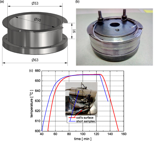
Figure 2. 3D drawing of the stainless steel former (a) and wound coil prior to final heat treatment with the fixed ends for current terminals (b) and heat treatment profile applied for W&R coil and its view with two thermocouples placed with short samples and at the outer layer of winding (c).
Download figure:
Standard image High-resolution image2.3. Low-temperature measurements
The I–V curves of the short samples were measured far above the critical current criterion with a constant current ramping of 0.43 As−1, and the ratio of the quench current (Iq) to the critical current (Ic) was estimated. The transport critical current measurements were performed by a standard DC current transport measurement for 50 mm long samples with a 1 μVcm−1 criterion at liquid He temperature and external magnetic fields from 4.5 to 8 T. Critical currents were also measured for the 70 mm long sample in sub-cooled water ice at temperatures between 33.25 K and 36.75 K and currents limited to I < 120 A. Short (5 ms) pulse current (PC) measurements were done in sub-cooled water ice in the self-field at a temperature range of 33–38 K.
The I–V curves and critical currents of the W&R coil were measured at 4.2 K and external fields between 5.5 T and 7.0 T on the length of 10.47 m. Measurements in self-field conditions were performed at temperatures between 33 K and 36.5 K inside the water ice cooled via the two-stage cryocooler Sumitomo RDK-408D2.
Figure 3 shows the system used for measurements in various environments (He gas, LN2, SN2 and water ice) at temperatures down to 12 K without the use of liquid helium. The temperature of the sample holder is controlled by a heater and three thermometers fixed to the sample center. The coil holder is fixed to the second stage of the Sumitomo RDK-408D2 cryocooler, and the whole assembly is placed inside a non-metallic cryostat. A small container was fixed to the sample holder and filled with around 0.5 l of water, whose temperature was monitored by three Pt100 thermometers located at positions 2 cm below, in the middle, and 2 cm above the coil. The cooling of water from room temperature down to 12 K takes around 10 h. All needed parameters were monitored and controlled by Laboratory Virtual Instrument Engineering Workbench (LabVIEW) from National Instruments.

Figure 3. Arrangement used for self-field measurement of W&R coil immersed in sub-cooled water ice inside the non-metallic cryostat of 300 mm in diameter.
Download figure:
Standard image High-resolution image3. Results and discussion
3.1. I–V characteristics of MgB2/Nb/CuNi30 wire
Figure 4(a) shows the I–V characteristics of CuNi30 sheathed wire at 4.2 K and external fields 6.5–8.0 T measured above the critical current criterion up to the quench, at which the current is fully expelled from MgB2 filaments into metallic elements. As one can see, it occurred at a relatively low quench power (Iq × V) of ∼13 mW in comparison to wires with less resistive sheath, e.g. ∼80 mW for the wire with the Al + Al2O3sheath made from 99.995% purity Al powder [7]. Figure 4(b) compares the Iq/Ic ratio derived from the I–V curves expressing the thermal stability for three similar multicore MgB2 wires differing by the outer sheath [25]. One can see a low Iq /Ic ratio for wires with CuNi30 and low-purity Cu (99.85% > 0.15% of impurities and >0.02% oxygen content) sheaths, meaning poorer thermal stability in comparison to that with low-purity Al [25].

Figure 4. Log–log I–V characteristics of MgB2/Nb/CuNi30 wire in liquid He (a) and corresponding quench currents to critical ratios Ic/Iq of this wire compared with low-purity Cu-99.85% sheathed seven-filament (7 f, Cu) and six-filament Al sheathed (6 f, Al) wires (b).
Download figure:
Standard image High-resolution imageFigure 5(a) shows the I–V characteristics of the presented wire measured under self-field conditions and temperatures between 33.25 K and 36.75 K cooled by water ice. Some resistive tails are observed for voltages below 1 µV and currents above 10 A, which can be attributed to the current transfer through the resistive CuNi30 sheath. It is apparent that this wire cooled by water ice is in not heated above the critical temperature and I-V curves can be measured safely up to a power of I × V > 150 mW (at 10 mm length of sample), which is more than one order of magnitude higher than for cooling it by liquid helium ∼13 mW (at 6 mm); see figure 4(a). Figure 5(b) shows the selected I–V curves measured up to higher voltages (>10−3 V), where some heating of the wire is very visible above 2 × 10⁻⁴V and I–V becomes a fully resistive state, which was not possible to reach with liquid He cooling (see figure 4(a)). The presented results confirm the improved thermal stability of the measured wire in the water ice, having high thermal conductivity and capacity in comparison to the liquid He bath conditions.
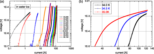
Figure 5. Log–log I–V characteristics of MgB2/Nb/CuNi30 wire measured in water ice between 33.25 K and 36.75 K (a) and selected I–V measured up to voltages of 1.5–2.5 mV (b).
Download figure:
Standard image High-resolution image3.2. Critical currents of MgB2/Nb/CuNi30 wire
Critical currents of MgB2/Nb/CuNi30 wires are shown in figure 6. Figure 6(a) presents the Ic(B) values of short samples taken from both ends of the 11 m long piece of the wire measured in the liquid He bath and at external fields of 4.5–8.0 T, and figure 6(b) shows the Ic(T) characteristics of the short sample annealed at 655oC/25 min min measured in the self-field by DC, as well as by PC, at a temperature range of 29–37 K. It is evident that a heat treatment temperature between 645 °C and 655 °C has an insignificant effect on the Ic values. Similarly, a tolerably small difference in the critical currents was measured between both ends of the wire; see figure 6(a). Figure 6(b) presents the critical currents measured by direct currents up to 100 A and by short pulse currents up to 500 A minimizing the wire heating. It is shown that both kinds of measurements give nearly the same Ic values at temperatures between 34 and 36 K, but slightly increased PC values below 34 K due to the suppressed sample heating. The MgB2/Nb/CuNi30 wire shows Ic > 100 A for B < 6 T at 4.2 K, and below the temperature of 33 K in the self-field, which represents an engineering current density Je > 104 Acm−2.

Figure 6. Critical currents of MgB2/Nb/CuNi30 short samples from both ends (red/blue) of 11 m long wire heat treated at 645 °C and 655 °C/25 min (a) and critical currents versus temperature measured in the water ice by DC and short (5 ms) current pulses for heat treatment at 655 °C/25 min.
Download figure:
Standard image High-resolution image3.3. I–E characteristics of W&R coil
Figure 7(a) shows the I–E characteristics of the W&R coil measured at 4.2 K and external fields 5.5–7.0 T. Due to the long wire length in the present coil and 10.47 m distance between potentials, the log–log I–E plot at 4.2 K can be obtained between 10−8 and 10−6Vcm−1 without any resistive tails. However, figure 7(a) does not show an ideal power law E ∼ In (linear relation in log–log plot), and E(I) is slightly convex (see the dashed linear line for 6 T data). Figure 7(b) shows the I-E characteristics of the coil measured between 33 K and 36.5 K, which have in comparison to 4.2 K a slightly concave character. In addition, I–E measured below 34.5 K has some resistive tails above 10−8Vcm−1. These differences are not yet fully understood, but can be attributed to various resistances of the used CuNi sheath and inter-turn connections in the non-insulated coil in the liquid He bath and inside the solid water ice, where the effect of mechanical stress cannot be excluded. Figure 7(c) compares the I–E characteristics for a coil length of 10.47 m with the same Ic at 4.2 K and 33.5 K and also the I–E of short samples (5 and 10 mm) with comparable Ic measured in liquid He and in water ice. One can see that the short wire samples show a greater steepness of I–E in comparison to the coil. The short samples do not allow us to obtain E ∼ In below 10−6Vcm−1 due to the resistive tails caused by current transfer through the resistive CuNi sheath. While the short sample presents local characteristics of MgB2 wire, an averaged characteristic is obtained for coil, where the voltage was measured on a much longer length and non-insulated turns. Therefore, the I–E characteristics of non-insulated coils will be simulated and analyzed in more detail in the future.

Figure 7. Log–log I–E characteristics of W&R coil measured in liquid helium (a), I–E in water ice (b) and comparison of coil I–E for the same Ic at 4.2 K and 33.5 K together with I–E of short sample at 4.2 K and 33.2 K (c).
Download figure:
Standard image High-resolution image3.4. Critical currents of W&R coil
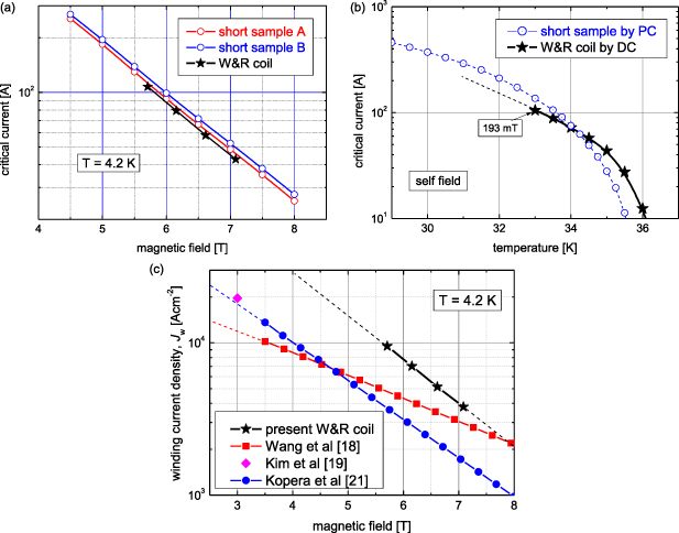
Figure 8(a) shows the critical current of the W&R coil estimated from the I–V characteristics shown in figure 7(a) compared with the Ic of short samples A and B taken from both ends of the long wire used for the W&R coil. The external field of the coil was corrected by the coil's field contribution in the center of the inner turns corresponding to ΔB = 1.937 mTA−1. Critical currents of the coil are 3.8% lower than the Ic of short sample A and 10.4% lower than sample B. This indicates an only slightly lowered quality of the whole wire wound into coil in comparison with short sample A. The mentioned differences in Ic can be affected by the not ideally uniform temperature inside the heat-treated coil; see figure 2(c). This means that the in-length uniformity of the used MgB2 wire with CuNi30 sheath is much better than that of the wire with Cu sheath made by a similar diffusion process having a variance of Ic of 25% over a distance of 10 m [26]. The observed improvement in longitudinal uniformity of the wire in the present coil can be attributed predominantly to the applied CuNi sheath, which is mechanically stronger than copper.
Figure 8. Critical currents of W&R coil at 4.2 K compared with short samples from both wire ends (a), critical currents of W&R coil in water ice compared with short sample Ic obtained by PC (b) and comparison of winding current density of present W&R coil with comparable MgB2 coils presented by Wang et al [4], Kim et al [18] and Kopera et al [20] (c).
Download figure:
Standard image High-resolution image
Figure 8(b) shows the DC measured critical currents of the W&R coil in water ice compared with the Ic of the short sample obtained by PC measurement below 36 K. Both Ic(T) dependences have similar tendencies but different absolute values, which is caused by the applied measurement technique (DC or PC) as well as by different self-fields. While the effect of the self-field can be neglected for the short sample, the field generated by the coil's current is much higher, e.g. 193.7 mT for Ic = 100 A at the location of the inner turns. A critical current of 100 A corresponds to an engineering current density of Je = 104 Acm−2, and consequently the present coil shows high engineering current densities of Je > 104 Acm−2 for B < 5.7 T at 4.2 K and below 33 K in the self-field.
In addition, the present coil immersed in sub-cooled water ice shows successful and stable operation below 36 K. Water ice was firstly used for impregnation applied for pulsed magnets by Motokawa et al [27] and also recently for avoiding critical current degradation of small YBCO coils at 77 K by Wang et al [28]. According to our knowledge, the superconducting coil's operation cooled by water ice down to 12.2 K and measured between 33 and 36 K has not yet been presented.
Figure 8(c) compares the winding current densities of four MgB2 coils made by the W&R process. Nearly the same current density values are obtained by Kim et al [18] and Kopera et al [20] for small coils with Jw > 104 Acm−2 for B < 4.0 T. Wang et al increased Jw in higher fields (above 4.5 T) due to the applied carbon doping [4], but Jw > 104 Acm−2 is measured for B < 3.5 T. The presented W&R coil shows the highest winding current densities of Jw > 104 Acm−2 for an external field B < 5.63 T, which will be interesting for future applications of MgB2 windings, especially when cooled and stabilized by water ice.
4. Conclusions
We present the results of a water ice-cooled small-scale non-insulated MgB2 coil made by the W&R process. The test coil, immersed in a volume of water ice cooled down to temperatures below 37 K, has shown successful operation. The presented experimental results show that a non-insulated coil wound from rectangular MgB2 wire has a very high filling factor, good thermal stability and consequently also very high engineering and winding current densities. The operation of the superconducting MgB2 coil cooled and stabilized by water ice below 36 K is presented for the first time. The presented W&R coil with high current densities of winding will be interesting for future He-free applications of MgB2 cooled and stabilized by water ice.
Acknowledgments
This work was supported by the Slovak Scientific Agency under projects APVV-18-15287 and VEGA 2/0140/19.
Data availability statement
The data that support the findings of this study are available upon reasonable request from the authors.