
Abstract
BaZrO3 (BZO) one-dimensional artificial pinning centers (1D-APCs) aligned along the c-axis of the YBa2Cu3O7 (YBCO) have been adopted to enhance the magnetic vortex pinning in BZO/YBCO nanocomposite films. However, the pinning force density Fp of the BZO 1D-APCs remains moderate at temperatures near 77 K. A hypothesis of the major limiting factor is the defective BZO 1D-APCs/YBCO interface as a direct consequence of the large interfacial strain originated from the BZO/YBCO lattice mismatch of ∼7.7%. Herein, we explore enlarging the c-axis of the YBCO dynamically to reduce the lattice mismatch and hence to prevent formation of the defective BZO 1D-APCs/YBCO interface. Specifically, the c-axis enlargement was achieved by partial replacement of Cu with Ca on the YBCO lattice using strain-directed Ca diffusion into YBCO from two Ca0.3Y0.7Ba2Cu3O7−x (CaY-123) spacers of only 10 nm in thickness inserted into the 2 vol% BZO 1D-APC/YBCO nanocomposite thin films of ∼150 nm in total thickness. The achieved elongated c-axis is attributed to the formation of stacking faults induced by Ca-replacement of Cu on YBCO lattice. The reduced BZO/YBCO lattice mismatch allows formation of a coherent BZO 1D-APC/YBCO interface with negligible defects. This leads to an enhanced Fp value up to 98 GN m−3 at 65 K, which is 70% higher than that of the reference 2 vol% BZO 1D-APC/YBCO sample. Furthermore, the benefit of the enhanced pinning of the BZO 1D-APCs with a coherent interface with YBCO can be extended to a large angular range of the magnetic field orientation. This study reveals the significant effect of the BZO/YBCO interface on the pinning efficiency of BZO 1D-APCs and provides a promising approach to achieve a coherent interface in BZO/YBCO nanocomposite films.
Export citation and abstract BibTeX RIS
1. Introduction
One-dimensional artificial pinning centers (1D-APCs) grown along the c-axis of REBa2Cu3O7− x (REBCO, RE-rare earth elements Y, Gd, Sm, etc) exhibit strong correlated vortex pinning, thereby yielding high in-field critical current density (Jc) at magnetic field B//c-axis of 1D-APC/YBCO nanocomposite films [1–5]. Many materials capable of self-assemblage into 1D-APCs in REBCO films have been discovered including BaZrO3 (BZO) [6–12], BaSnO3 (BSO) [10, 13–18], BaHfO3 (BHO) [10, 19–22] and YBa2(Nb/Ta)O6 [22–25]. Nevertheless, these 1D-APCs are shown to provide vortex pinning with varying degrees of effectiveness [9, 10, 12, 17, 19–21, 23, 24]. Among others, BZO 1D-APCs have been intensively studied after the pioneer work by MacManus-Driscoll et al [1] and a semi-coherent BZO 1D-APC/YBCO interface of high defect density (such as dislocations) has been revealed due to the large lattice mismatch of ∼7.7%, and hence intensive strain at the BZO 1D-APC/YBCO interface [26, 27]. This defective interface has been argued to be an obstacle to realize the pristine pinning efficiency of the BZO 1D-APCs. While searching for new APC materials with a smaller lattice mismatch with REBCO is a possible resolution, the interface strain at an appropriate level serves as the driving force for the self-assembly of 1D-APCs in controlling their morphology [4], dimension [28, 29], orientation [30] and concentration [5] as suggested in the elastic strain energy modeling. In the BZO 1D-APC/YBCO nanocomposite films, the interface strain has shown to enable high concentration BZO 1D-APCs to be obtained proportional approximately linearly with the BZO doping [31].
Therefore, an ideal interface engineering scheme should achieve a coherent BZO 1D-APC/YBCO interface dynamically during the growth of the BZO 1D-APCs, after the BZO 1D-APCs nucleation while before defects form at the interface. Motivated by this, we explore dynamic Ca-replacement of Cu cations on the YBCO lattice for an enlarged c-axis lattice constant near the BZO 1D-APC/YBCO interface since the ionic radius Ca is 30% larger in dimension than that of Cu [32]. Ca is provided from two Ca0.3Y0.7Ba2Cu3O7− x (CaY-123) spacers of 10 nm in thickness inserted into the 2 vol% BZO 1D-APC/YBCO nanocomposite thin films (total thickness around 150 nm) in a multilayer (ML) form. This allows the diffusion of Ca from the spacers into YBCO to enlarge the c-axis of YBCO by partially replacing a smaller Cu cation with a larger Ca cation. Remarkably, this dynamic interface engineering process has been shown to promote the formation of stacking faults on the YBCO lattice near the BZO/YBCO interface, leading to the local elongation of the YBCO c-axis up to ∼1.24 nm. This reduces the BZO/YBCO lattice mismatch from 7.7% to ∼1.4% and the formation of a coherent BZO 1D-APC/YBCO interface. The improved pinning efficiency of the BZO 1D-APCs is illustrated in the significantly enhanced Fp values at 65 K together with reduced pinning anisotropy especially at high magnetic fields.
2. Experimental
2 vol% BZO 1D-APC/YBCO nanocomposite ML films (2% BZO-YBCO ML) were fabricated using pulsed laser deposition (PLD) using two PLD targets of the 2 vol% BZO doped YBCO (2% BZO-YBCO) and CaY-123. The former was also used to make the reference 2 vol% BZO 1D-APC/YBCO single-layer (SL) films to be regarded as 2% BZO-YBCO SL sample. For the ML samples, two CaY-123 spacers were inserted in a 2% BZO-YBCO film by depositing the 2% BZO-YBCO and CaY-123 layers from the two PLD targets alternatively. Specifically, the 1st, 3rd and 5th layers of thickness ∼50 nm each were 2% BZO-YBCO and the 2nd and 4th layers were 10 nm thick CaY-123. The optimal PLD repetition rates were 8 Hz and 2 Hz for 2% BZO-YBCO and CaY-123 layers respectively for both SL and ML samples. It should be noted that these PLD repetition rates were found optimal to facilitate Ca/Cu replacement and minimize other cation replacement by Ca to reduce the Tc of the ML samples [33, 34]. The thickness of the BZO-YBCO ML and SL samples was in a range ∼160–170 nm measured using a KLA Tencor P16 profilometer. Both sets of the films (SL and ML) were fabricated on (100) SrTiO3 (STO) single crystal substrates at the substrate temperature of 825 °C in 300 mTorr oxygen environment. After the PLD deposition, the films were annealed in one atmosphere oxygen for 30 min at 500 °C. The full details of SL film fabrication have been reported previously based on PLD condition optimization [11, 35, 36]. The microstructures of the SL and ML samples were imaged using Cs-corrected transmission electron microscopy (TEM) and scanning transmission electron microscopy (STEM). A Thermo Fisher Scientific TALOS F200X TEM with a resolution of 1.6 Å was used to acquire TEM and STEM results. The STEM was taken under a high angle annular dark field mode (HAADF). In addition, a new generation microscope (Thermo Fisher Scientific Themis-Z TEM system) was used to capture high-resolution STEM (HRSTEM) images with a resolution as good as 63 ppm. X-ray diffraction (XRD) θ − 2θ scans were measured using a Bruker D8 diffractometer with Cu–kα radiation of wavelength 1.54 Å. The XRD peak intensities of each film were normalized to that of the YBCO (005) peak, the strongest in the (001) peaks for YBCO, for the comparison purpose. The Bruker D8 Discover was used to collect data for a rocking curve scan of the YBCO (005) peak. The software provided by Bruker, EVA, was then utilized to calculate the full width at half maximum (FWHM). The software conducts statistical computations to compile the area under the peak and the position of the peak maximum. FWHM is the width of the spectrum curve measured at half the maximum intensity recorded for the specific peak. Two microbridges of length of 500 μm, and widths of 20 μm and 40 μm respectively, were patterned on each film using standard photolithography. The critical current density Jc = Ic/A, was calculated from the film's bridge cross-sectional area, A and the critical current Ic. Ic was measured at different applied magnetic field B (0–9 T) at 65 K and 77 K and different B field orientation (θ) in a Physical Property Measurement System (Quantum Design Evercool II). Specifically, θ was varied in the range from θ = 0° (H//c-axis) to θ = 90° (B//ab-plane) in the plane perpendicular to the Jc. The Jc(B) values were determined using the 1 μV cm−1 criterion on the I–V characteristic. The selection of the θ angles is based on a preliminary test of the Fp(B) and Jc(B) curves to ensure the difference between the curves at these angles is not negligible [37]. The pinning force density (Fp) was calculated from the equation Fp = Jc × B. The maximum pinning force density (Fp,max) and its location (Bmax) are then determined from the Fp(B) curve.
3. Results and discussions
Figure 1 depicts the BZO-YBCO SL (a) and ML (b) nanocomposite films schematically. A major difference between the two kinds of samples is the presence of CaY-123 layers (purple) in the latter. The CaY-123 layers serve as the Ca reservoir to allow Ca diffusion to the 2% BZO-YBCO layers as indicated by the purple arrows in figure 1(b). It should be noted that Ca/Y, Ca/Ba and Ca/Cu replacements are all possible depending on the strain status of the YBCO films. As revealed in a first principle simulation on bulk YBCO by Klie et al [32], Ca/Cu replacement would be preferred when the YBCO is under a tensile strain. From the elastic strain energy consideration, this is expected considering a larger Ca cation replacing a smaller Cu cation on a tensile strained YBCO would lead to enlarged c-axis with a reduced elastic energy. Since the tensile strain would be the highest at the BZO/YBCO interface before defects formation [26], the strain-directed Ca/Cu replacement would most probably occur at or near the BZO/YBCO interface during the nanocomposite film growth. In the 2% BZO-YBCO SL or ML films, the spacing between the BZO 1D-APCs is around 20 nm, strain field overlap may barely occur [26], which means that the Ca/Y replacement is also possible in the 2% BZO-YBCO layer away from the BZO 1D-APCs where strain is negligible. Consequently, reduced Tc is anticipated due to Ca/Y replacement [33, 34]. It should be noted that the ML scheme was previously adopted on bi-crystal YBCO films to facilitate Ca diffusion to the grain boundary (GB) for compensation of oxygen deficiency at GBs. Reduced obstruction effect of the Ca-doped GBs on inter-grain Jc was reported [38, 39]. However, the role of Ca diffusion in the BZO-YBCO ML samples in this work is to induce a dynamic Ca/Cu replacement immediately after the BZO 1D-APC formation to prevent the defective BZO/YBCO interface to from at the BZO/YBCO interface, which differs fundamentally from the ML bicrystal YBCO case.
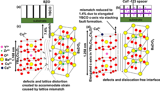
Figure 1. Schematic diagram of (a) a SL BZO/YBCO nanocomposite film with a BZO/YBCO interface region with high number of defects and dislocation created during growth to accommodate the strain due to the ∼7.1% lattice mismatch between YBCO and BZO and (b) ML YBCO/(Ca0.3Y0.7)123/YBCO nanocomposite film BZO/YBCO interface region with minimal or no defects and dislocations. This is attributed to the reduction in lattice mismatch due to local elongation of YBCO c-axis after the formation of Ca2+/Cu2+ replacement induced planar defects formation (stacking faults).
Download figure:
Standard image High-resolution imageFigure 2 compares the STEM and HRSTEM images of cross sections of the 2% BZO-YBCO SL (figures 2(a)–(c)) and 2% BZO-YBCO ML (figures 2(d)–(f)) samples. The c-axis aligned BZO 1D-APCs can be clearly seen embedded in both kinds of the samples with comparable morphologies and concentrations (figures 2(a) and (d)). This is anticipated since the Ca/Cu replacement occurs after the BZO 1D-APCs form and is therefore not expected to affect the nucleation of the BZO 1D-PACs. In the BZO-YBCO ML film, the BZO 1D-APCs are segmented by the CaY-123 spacers, in contrast to the continuous BZO 1D-APCs in the SL case. Previous studies on ML YBCO nanocomposites doped with BZO and other 1D-APCs have reported segmented 1D-APCs due to the truncation of the 1D-APCs by the alternating YBCO layer (with no or much smaller APC doping) of thickness ⩾10 nm [40–42]. The observed enhancement in pinning at B aligned away from the c-axis is at the cost of reduced pinning at B//c-axis due to the reduced effective pinning force per film thickness by segmented 1D-APCs [41, 42]. By choosing very thin CaY-123 spacers (∼10 nm), the negative impact of the spacers both on the evolution of the BZO 1D-APCs and their specific pinning efficiency can be minimized as to be discussed later. However, differences on the microstructures of the YBCO matrix of the 2% BZO-YBCO SL and ML samples have been revealed in the HRSTEM images. In the BZO-YBCO SL sample, as shown in figures 2(b) and (c), a large concentration of dislocations and YBCO lattice distortion initiated from the BZO/YBCO interface are present, which is consistent with the previous reports [5, 27, 30, 43, 44] and can be ascribed to the large lattice mismatch of 7.7% between the BZO and YBCO [45–47]. In contrast, based on the Cs-corrected mid-mag STEM image of the BZO-YBCO ML film shown in figure 2(e), such dislocations and lattice distortion are almost negligible and the BZO/YBCO interface looks highly coherent. The Cs-corrected HRSTEM image shown in figure 2(f) was taken from the film/substrate interface area containing the Ca-doped regions (as the white arrows indicated in figure 2(e)) in the BZO-YBCO ML film. The dark contrast regions in figures 2(d)–(f) are believed to be Ca rich regions, i.e. YBCO lattice distorted areas caused by the substitution of Ca with Cu atoms in YBCO structure. This is based on both the STEM imaging contrast and EDX mapping results. First, the STEM imaging under HAADF condition presents a specific relationship between STEM image intensity (I) and atomic number (Z): I ∝ Z1.7 [48]. Thus, the chemistry of the atomic columns and areas can be identified based on the contrast in the HRS-
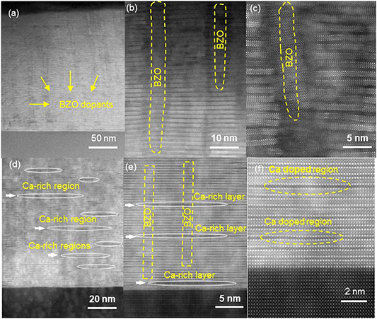
Figure 2. TEM and HRTEM cross-section images of 2% SL (a)–(c); and on 2% ML (d)–(f). The TEM images ((a) and (d)) show c-axis aligned BZO APCs grown through the films' thickness. The HRTEM image of the 2% SL ((b) and (c)) show distortions and dislocations in the YBCO matrix which are absent in the 2% ML HRTEM images ((e) and (f)). The white ellipses shown in the 2% ML HRTEM image ((d)–(f)) are Ca-doped regions which elongate the c-axis lattice of YBCO matrix.
Download figure:
Standard image High-resolution imageTEM image, i.e. the heavier elements with high Z numbers show brighter contrast that that of the light elements. Therefore, because the lower Z number of Ca than Y, Ba and Cu, the Ca rich regions could exhibit dark contrast as seen in the dark distorted regions. Second, we have conducted an EDS line scan analysis across one dark region in the HRSTEM image (as shown in figure S1 available online at stacks.iop.org/SUST/34/104002/mmedia in supplemental information), showing that higher Ca concentration in the dark lattice regions (as shown in the enlarged image correspondingly on the right), which further confirmed that the stacking faults are Ca-rich regions. Owing to the lattice distortion and stacking faults formation at the Ca-doped areas, the YBCO lattice around these features has an elongated c-axis lattice constant up to 1.24 nm. This explains the highly coherent BZO/YBCO interface with much less obvious lattice distortion due to the reduction of the lattice mismatch to as small as ∼1.4%. As we have mentioned earlier, Ca could replace Y, or Ba, or Cu on the YBCO lattice depending on the strain status of the YBCO matrix. The observation of predominant Ca/Cu replacement in the 2% BZO-YBCO ML sample confirms that the diffusion of Ca into the YBCO occurs in a dynamic manner driven by the tensile strain originated from the formation of BZO 1D-APCs of larger lattice constant in YBCO of the smaller pristine c-axis lattice constant. In order to identify the Ca/Cu substitution across Ca-doped BZO/YBCO regions, an intensity line profile (the red rectangle in figure 3(a)) and a zoom-in view in figure 3(b) with the arrow indicating the scan direction on the stacking fault at the center of the figure has been retrieved based on the HRSTEM image in these figures. The atom columns can be identified based on their different line profile intensities, where the Ca-doped regions on the YBa2Cu3−
x
Cax
O7−
δ
unit cell can be clearly seen in figure 3(c). Because of the relationship between STEM image intensity (I) and atomic number (Z), i.e. I
 Z1.7, the substituted Ca atomic columns demonstrate obviously lower intensity than that of Cu columns, as indicated in figure 3(c). This confirms that the observed planar defects or stacking faults are primarily induced by Ca/Cu replacement on the YBCO lattice, resulting in elongated c-axis lattice constant in the local region around the defects.

Figure 3. (a) High-resolution cross-sectional STEM image of 2% ML film. (b) Zoom-in view of the red rectangular Ca-doped region in the HRSTEM image in (a). (c) The intensity line profile across the Ca-doped region within the YBCO matrix as the yellow arrow indicated in (b). The Cu and Ca atoms are identified based on their different line profile intensities.
Download figure:
Standard image High-resolution imageFigure 4(a) compares the XRD θ –2θ spectra of 2% BZO-YBCO SL (red) and 2% BZO-YBCO ML (black) films. The appearance of the YBCO (001) peaks (#) indicates the c-axis orientation of the BZO/YBCO nanocomposite films on the (100) STO substrates (+). In addition, a major BZO (001) peak at ∼46.5° appears in all three samples. Based on the YBCO (001) peaks, the c-lattice constants can be estimated to be 11.746 Å and 11.766 Å for the 2% BZO-YBCO SL and ML samples, respectively. The increased c-axis lattice constant in the SL sample is anticipated from the tensile strain induced via self-assembly of the BZO 1D-APCs in the BZO/YBCO nanocomposites and the value seems consistent to that in previous reports [49, 50]. The further increased c-axis lattice constant in the 2% BZO-YBCO ML sample may be ascribed to the partial Ca/Cu replacement on the YBCO lattice as revealed in the TEM analysis. It should be noted that the local c-axis lattice parameter of YBCO in the ML sample based on HRSTEM images is larger than the one based on XRD peak positions. This is not surprising since the former reflects the local property around the stacking faults while the latter is a global average over the entire sample. The difference between the two suggests that the Ca/Cu replacement most probably occurs locally in selected areas such as strongly tensile strained BZO/YBCO interface, instead of globally in the entire film. This argument seems consistent with the minor impact of the stacking faults on the Tc values of the ML samples (to be discussed below). Interestingly, the FWHM of the YBCO (005) peak shown in figure 4(b) illustrates a smaller value of 0.322 for the 2% BZO-YBCO ML sample than that of 0.356 for its 2% BZO-YBCO SL counterpart, indicating a smaller microstrain in the former. This is not surprising since the elongated YBCO c-axis lattice constant via Ca/Cu replacement would reduce the strain field especially at the BZO/YBCO interface and prevent the defect formation. It is important to note that the 2% BZO-YBCO ML c-lattice parameter is smaller than that obtained using the HRSTEM. This may be attributed to the nature of the local Ca/Cu replacement, mostly near the YBCO/BZO interface where the tensile strain is the highest to drive the Ca/Cu replacement, and the consequent local elongation of the c-lattice. The minor Ca diffusion into YBCO lattice is also illustrated in the slightly lower Tc of ∼87.5 K for the 2% BZO-YBCO ML film [33, 34], which is 1 K lower than that of the 2% SL sample.
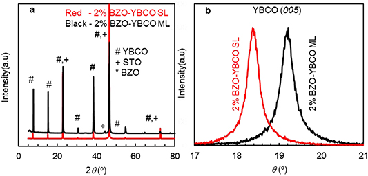
Figure 4. XRD scans. (a) θ − 2θ scans taken on 2% BZO-YBCO SL (red) and 2% BZO-YBCO ML (black). The spectra were generated using Cu–kα radiation of wavelength 1.54 Å. The symbols #, + and * represent the YBCO (001), STO substrate (100) and BZO (001) peaks respectively. (b) Rocking curves of the YBCO (005) peak for SL (red) and ML (black) films. The narrower FWHM in the ML curve indicates reduced microstrain due to calcium doping.
Download figure:
Standard image High-resolution imageFigure S2 is a plot of the resistance (R) as a function of temperature (T) at B = 0 T for the 2% ML (solid line) and 2% SL (dashed lines). The R values at 300 K are 270 Ω for the ML film and 460 Ω for the SL film. The ML film exhibit a stronger metallic behavior with ΔR/(300 K − 100 K) of 0.85 Ω K−1 in contrast to the 1.6 Ω K−1 value for the SL sample. Nevertheless, the Tc values are ∼86.5 K and 87.5 K for the ML sample and SL film, respectively. Figure 5 compares the Jc(B) (a) and Fp(B) (b) curves of the 2% BZO-YBCO SL (open) and 2% BZO-YBCO ML (solid) films at B//c, and at 77 K (red) and 65 K (black). At 77 K, the 2% BZO-YBCO SL and ML samples have self-field (SF) Jc of 0.92 MA cm−2 and 1.7 MA cm−2, respectively. The higher Jc values of the 2% BZO-YBCO ML sample were observed in the field range up to ∼6.0 T despite a lower Tc (by ∼1.0 K) relative to that of the 2% BZO-YBCO SL sample. At B = 1.0–3.0 T, for example the enhancement is by a factor of 1.8–2.0. A much more significant Jc enhancement can be observed over the entire B field range up to 9.0 T at 65 K when the Tc effect is insignificant. For example, at 1.0 T, 5.0 T and 9.0 T, the Jc value of 4.39 MA cm−2, 1.58 MA cm−2 and 0.59 MA cm−2 for the ML sample are about 1.7, 1.8 and 2.7 times of that of the SL film. Figure 5(b) compares the FP(B) curves of the 2% BZO-YBCO SL (open) and 2% BZO-YBCO ML (solid) samples at 77 K (red) and 65 K (black), respectively. It should be noticed that the FP(B) curves at 77 K were magnified by five times (or 5×) for better visibility. Qualitatively, all FP(B) curves exhibit an inverted bell shape with a peak value of Fpmax located at Bmax. Interestingly, the 2% BZO-YBCO ML and 2% BZO-YBCO SL samples have comparable Bmax values of 3.0 T, which is smaller than the accommodation field (∼5.0 T) calculated from B* = n*Φo, based on the flux quantum Φo ∼ 2.07 × 10⁻¹⁵ Wb and areal density n* of the BZO 1D-APCs acquired from TEM characterization [19, 51]. Therefore, the insertion of the CaY-123 spacer layer does not seem to affect the self-assembly of the BZO 1D-APCs in the 2% BZO-YBCO ML samples. The pinning improvement in the 2% BZO-YBCO ML sample is illustrated in the overall higher FP values almost over the entire B field range. At 77 K, the Fpmax of ∼10.7 GN m−3 in the 2% BZO-YBCO ML film is almost twice of the value for the 2% BZO-YBCO SL (6.1 GN m−3) and close to the value of ∼12.5 GN m−3 reported for the 2% BHO/YBCO film [19]. Similarly, the Fpmax of ∼97.7 GN m−3 for the ML sample at 65 K is 1.7 times of the Fpmax of ∼57.1 GN m−3 in the 2% BZO-YBCO SL sample and surpasses the ∼80 GN m−3 of the 2% BHO-YBCO SL sample [19]. It should be noted that the Fpmax values for the 2% BZO-YBCO SL sample are comparable to that reported in literature [12, 14, 52, 53]. Therefore, the improved pinning by the BZO 1D-APCs in the 2% BZO-YBCO ML sample could be attributed to better straightness of BZO 1D-APCs, highly coherent BZO/YBCO interface, as well as much better film epitaxial quality than in the SL counterpart case.
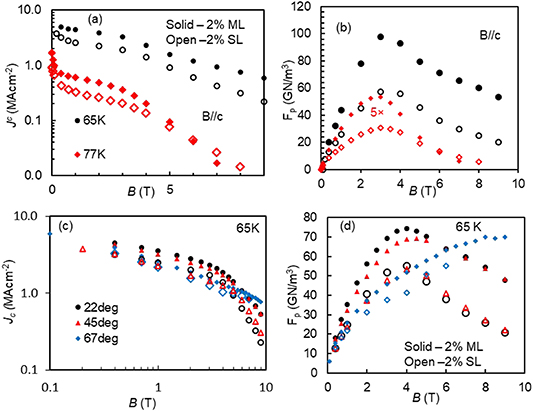
Figure 5. Comparisons at of Jc(B) and FP(B) curves of the 2% BZO SD SL (open symbols) with 2% BZO SD ML (solid symbols) nanocomposite films along B//c ((a) and (b)) at 77 K (diamond) and 65 K (circle) and along other angles ((c) and (d)) at 65 K. In (b), the FP data at 77 K is magnified by five (right axis) to make visible in the panel.
Download figure:
Standard image High-resolution imageThis pinning enhancement has been found to extend beyond the B//c orientation as can be seen in figures 5(c) and (d) in comparison of the Jc(B) and FP (B) curves of 2% BZO-YBCO SL (open) and ML (solid) measured at selected θ angles of 22° (black), 37° (blue), 45° (red) and 67° (purple), respectively at 65 K. The Fpmax values at 22°, 37°, 45° and 67° in the 2% BZO-YBCO ML samples are significantly larger than the corresponding values in the 2% BZO-YBCO SL film. For example, at 22° Fpmax is ∼74.3 GN m−3 for the 2% BZO-YBCO ML and only 55.3 GN m−3 for the 2% BZO-YBCO SL sample. At 67°, the Fpmax of ∼70.0 GN m−3 measured on the 2% BZO-YBCO ML represents a ∼70% enhancement over the Fpmax ∼ 41.2 GN m−3 for the 2% BZO-YBCO SL film. Based on Blatter's scaling [54] for vortex interaction with materials such as YBCO, Jc at 65 K should scale as Jc (65 K, B(θ)) = Jc (77 K, B eff(θ)). Here eff(θ) = [cos2
θ + γeff sin2
θ]1/2 with γeff been the effective equivalent of intrinsic anisotropy of YBCO, γ = mc
/mab
where mc
and mab
are the effective masses along the c and ab directions respectively. For undoped YBCO γ = ∼5.0–7.0. For this study, Jc was scaled using the approach suggested here [55] and γeff ∼ 2 was used to account for BZO doping [9, 56, 57]. Figure S3 shows the plot of Jc (65 K) for the ML (a) and the SL (b) films as a function of Beff (=Beff(θ)) for θ = 22°–67°. The plot corresponds to the relatively enhanced Jc seen in the ML film up to ∼70° in 3 T and 4 T (figure 5(c)). In addition, the absence of extensive collapse of curves in both films indicate the absence of significant isotropic pinning in the films [56].
eff(θ)). Here eff(θ) = [cos2
θ + γeff sin2
θ]1/2 with γeff been the effective equivalent of intrinsic anisotropy of YBCO, γ = mc
/mab
where mc
and mab
are the effective masses along the c and ab directions respectively. For undoped YBCO γ = ∼5.0–7.0. For this study, Jc was scaled using the approach suggested here [55] and γeff ∼ 2 was used to account for BZO doping [9, 56, 57]. Figure S3 shows the plot of Jc (65 K) for the ML (a) and the SL (b) films as a function of Beff (=Beff(θ)) for θ = 22°–67°. The plot corresponds to the relatively enhanced Jc seen in the ML film up to ∼70° in 3 T and 4 T (figure 5(c)). In addition, the absence of extensive collapse of curves in both films indicate the absence of significant isotropic pinning in the films [56].
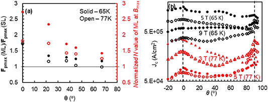
To quantify the pinning enhancement, the Fpmax values of the BZO-YBCO ML was normalized to that of the SL counterpart at different θ angles. The normalized Fpmax values (black) are plotted as function of θ in figure 6(a) at 77 K (open) and 65 K (solid) respectively. As expected, the data shows a monotonic decrease in the normalized Fpmax with θ and the highest enhancement factor of 1.7 is at θ = 0° as expected. At 65 K when the Tc effect is negligible, larger enhancement factors can be observed in the entire angular range despite a similar trend of monotonic decreasing enhancement factors with increasing θ angles, which is similar to the case of BHO 1D-APCs that also form a coherent interface with YBCO matrix [37, 58]. The highest enhancement factor of 1.7 is at θ = 0° and it is ∼1.0 at θ = 67°. In an attempt to illuminate the pinning mechanism, the reduced pinning force density f = Fp/Fpmax was plotted as a function of reduced magnetic field b = B/Bmax [59, 60] for both films at 65 K along B//c, 22° and 45° in figure S4 (supplemental information). Bmax ranges from ∼3.0 T to 4.0 T for θ ⩽ 45° and undefined for from 67°. The large undetermined Bmax at ⩾67° may be attributable to strong intrinsic pinning in both films. The fit (black line) was calculated using f = abp (1 − b)q [61, 62], where a, p and q are fitting parameters. For pristine YBCO, the exponents p and q have been reported to be ∼0.5 and ∼2.0 respectively [63, 64]. Part of the curve which scales indicate the pinning scaling up to a single curve till bmax (location of fmax). The value of bmax shifts from 0.33 along B//c to 0.44 at 22° and 45°. Along B//c, the pinning may be attributed to normal core pinning since the fitting parameters p and q are ∼1 and ∼2 respectively [65]. Beyond bmax, the ML film shows enhancement at all three B orientations confirming the high field Jc and Fp data in figure 5.
Figure 6. The pinning properties of the films. (a) The FPmax ratio (black) and N-value at Bmax of the ML film normalized to that of the SL film (red) as a function of (θ) at 77 K (open) and 65 K (solid); and (b) Jc(θ) data at 77 K (red) in 3 T (triangle), and 5 T (circle); and at 65 K (black) in 5 T (circle) and 9 T (diamond) for 2% SL (open) and 2% ML (solid).
Download figure:
Standard image High-resolution image
Figure 6(a) also compares the N values for the 2% BZO-YBCO ML and SL samples, which is proportional to the pinning potentials of the BZO 1D-APCs in the two cases, by fitting the power law on the I–V curves: the V ∼ IN [66–69]. The N values (red) at Bmax of the ML sample, normalized to that of the SL film, are plotted as functions of θ at 77 K (open) and 65 K (solid) in figure 6(a). Interestingly, the normalized N value vs θ curve follows a similar trend to that of the normalized Fpmax (θ) curve with an overall enhancement in the entire angular range up to at θ ∼67°. The highest normalized N value ∼2.7 can be observed at B//c and 65 K. This result is consistent with the overall enhanced Jc(θ) as illustrated in figure 6(b). At 65 K (black), the Jc(θ) of the 2% BZO-YBCO ML (solid) exhibit considerably higher values as compared to that on the SL counterpart (open) in almost the entire angular range up to >85° at high fields of 5 T and 9 T. Figure S5 is a direct plot of the N-value at Bmax of both films with respect to θ at 65 K–77 K. The N-value oscillates with θ, especially at 65 K, and this behavior has been reported here [70]. The biggest value of ∼110 was recorded in the ML film along B//c. The significant enhancement in the ML film along all B orientations at 65 K corresponds well with similar enhancement in Jc (5 T) shown in figure 6(b). This angular enhancement in Jc for the 2% BZO-YBCO ML (relative to the 2% BZO-YBCO SL case) is consistent with what has been reported on the BHO/YBCO nanocomposite films in which the BHO 1D-APC/YBCO interface is coherent [37, 58]. At 77 K (red curves of figure 6(b)), the angular range of higher Jc(θ) in the ML sample becomes slightly reduced, most probably due to the Tc effect.
It should be noted that MLs containing YBCO and Ca-doped YBCO constituent layers have been reported on bicrystal substrates to reduce the obstruction of the GB on the so-called inter-grain Jc that depends exponentially on the GB angle and hence is significantly reduced from the intra-grain Jc of YBCO [33, 34]. The local Ca diffusion into the GB is to overdope GB (by replacing Y + 3 with Ca + 2) beyond that of optimal YBCO in order to reduce the build-in potential and hence the GB's tunneling barrier's height and width to reduces GB's obstruction on the inter-grain Jc. Nevertheless, the enhanced inter-grain Jc in these ML samples is still much below the intra-grain Jc for YBCO. In particular, the Jc investigated in this work is primarily SF Jc, which was shown to reach 4.3 × 10⁵ A cm−2 at 77 K in ML YBCO films on bicrystal substrates of 24° GB angle. However, the microscopic mechanism underlying the role of Ca in BZO/YBCO ML samples reported in this manuscript differs fundamentally. Specifically, the effect of Ca is to generate planar defects or stacking faults on YBCO for an enlarged c-axis lattice constant near the BZO/YBCO interface via induced formation of stacking faults through strain facilitated Ca/Cu replacement on YBCO lattice, and hence to dynamically reduce the lattice mismatch at the interface. The purpose is to reduce the BZO/YBCO interface strain by reducing the lattice mismatch from 7.7% to about 1.4%, preventing formation of the defects at the interface. This allows us to achieve highly coherent BZO/YBCO interface, for the first time to our knowledge, and to probe the correlation between the BZO 1D-APC/YBCO interface and pinning efficiency of the BZO 1D-APC. The significantly enhanced pinning efficiency of the BZO 1D-APCs in the BZO/YBCO ML samples, as compared to case of their SL counterpart, illustrate that a coherent BZO/YBCO interface of negligible degradation of superconductivity is the key to high pinning efficiency of 1D-APCs.
4. Conclusion
In summary, a dynamic c-axis elongation process has been developed to reduce the lattice mismatch at the BZO/YBCO interface during the growth of the BZO 1D-APCs in PLD fabrication of the 2% BZO-YBCO ML nanocomposite films by insertion of two 10 nm thick CaY-123 spacers. There are two steps of this dynamic progress. During the 1st step, the initial BZO/YBCO interface interfacial strain originated from the large lattice mismatch of ∼7.7% is maintained to initiate the self-assembly of the BZO 1D-APCs. In the 2nd step immediately after the formation of the BZO 1D-APCs, a strain-directed Ca diffusion from the CaY-123 spacer to the BZO/YBCO nanocomposite leads to energetically preferred Ca/Cu replacement on YBCO and the elongation of its c-axis lattice constant, which reduces the BZO/YBCO lattice mismatch to ∼1.4% below the threshold of defect formation as confirmed in microstructural analysis using HRTEM. This dynamic interface engineering scheme allows the BZO 1D-APC of a coherent interface with YBCO matrix to be achieved in the 2% BZO-YBCO ML samples with a comparable concentration and morphology to that in their SL counterparts. Remarkably, the BZO 1D-APCs with a coherent interface with YBCO matrix exhibit considerably enhanced pinning efficiency demonstrated in the higher transported Jc and Fp measured at 65 K–77 K as function of B field up to 9.0 T, and higher N values than that of BZO 1D-APCs with a semi-coherent interface. For example, the Fpmax of ∼98 GN m−3 at B//c and 65 K in the 2% BZO-YBCO ML samples is nearly 1.7 times of that for the reference SL counterpart's, which is consistent with the higher N value of the former by a factor of 2.7 than that of the latter. Furthermore, the benefit of the enhanced pinning efficiency also extends to a large angular range as shown in the enhanced Jc, Fp, and N values in almost entire range of θ. This result demonstrates not only the critical importance of the BZO/YBCO interface in specific pinning efficiency of 1D-APCs, but also provides a facile approach to achieve it.
Acknowledgments
This research was supported in part by NSF Contracts Nos. NSF-DMR-1508494 and 1909292 and NSF-ECCS-1809293, the AFRL Aerospace Systems Directorate, US National Science Foundation Air Force Office of Scientific Research (AFOSR) LRIR #14RQO8COR and LRIR #18RQCOR100. D Z and H W acknowledge the support from the US National Science Foundation for the HRSTEM effort at Purdue University (DMR-1565822 and DMR-2016453).
Data availability statement
The data that support the findings of this study are available upon reasonable request from the authors.