

Abstract
AC loss in high temperature superconducting (HTS) coils affects the performance of HTS devices. Using magnetic flux diverters (MFDs) is an effective way to reduce AC loss in HTS coils. In this paper, measurement and finite element method simulation of AC loss results in a REBCO coil assembly comprising four double pancake coils with two molypermalloy-powder MFDs are presented. Both experimental and numerical results show that MFDs can significantly reduce the AC loss in the REBCO coil assembly while generating negligible loss in themselves. Further, the influence of the distance between the coil assembly and the diverters on AC loss reduction is explored. Compared with the AC loss data in the coil assembly without MFDs, over 80% AC loss reduction is achieved when the distance between the coil assembly and the diverters is at its minimum value, 2 mm. The simulation results reveal that the AC loss reduction in the coil assembly is mainly due to the reduction of the radial (perpendicular) magnetic field component to the surface of REBCO wires in the end windings of the coil assembly.
Export citation and abstract BibTeX RIS
1. Introduction
AC loss (energy loss due to alternating magnetic field) is one of the critical issues in HTS (high temperature superconducting) applications such as HTS motors/generators and HTS transformers [1–3]. Therefore AC loss reduction in HTS coils is one of key aspects in designing these HTS devices. Two types of commercialised HTS wires are commonly used for these applications: multifilamentary Bi-2223 wires and REBCO coated conductors [4, 5].
One fundamental problem with Bi-2223 wires in these applications is their large filament width which causes large AC loss in perpendicular magnetic field. Sufficient AC loss reduction can only be achieved by the combination of fine filament width, tight twisting, and high resistivity barriers separating the filaments [5]. Some other issues with the use of Bi-2223 wires in coil windings are their non-negligible AC loss in parallel magnetic field and poor in-field performance compared to REBCO coated conductors [6].
For REBCO coated conductors, achieving narrow filaments on the REBCO conductor surface through striation can reduce the hysteresis loss, which is proportional to the tape width [7, 8]. In [9], a solenoid coil wound with three-filament REBCO wires was built and the measurement result showed that the AC loss in the solenoid coil was 1/3 of that wound with non-striated wires. On the other hand, continuously transposed Roebel cables have been proven as an effective way to reduce AC loss [10, 11]. In a HTS Roebel cable, the current can be equally distributed among strands and the cable can be regarded as two parallel stacks carrying the same current in each strand [11, 12]. The magnetization loss of a Roebel cable can be reduced to half that of an equivalent stack with the same effective wire width [13]. In [14], 1 MVA transformer was successfully demonstrated with low-loss high current-capacity Roebel cables.
However, the methods for AC loss reduction mentioned above have drawbacks. Striation which is mainly achieved by laser cutting is costly and the resulting tapes are prone to coupling loss generated in the groove between the filaments due to conductance caused by imperfect cutting. Striation can also reduce the critical current density of the wires [15]. Roebel cables on the other hand are expensive; they involve strand cutting with associated waste of REBCO material and cable assembly steps [16].
The use of ferromagnetic flux diverters is another effective method to reduce AC loss in HTS coil windings comparable to using low loss conductors. Flux diverters are used to reshape the flux distribution around coil windings to reduce AC loss or increase critical current of DC coil windings [17–28]. Previous studies have proven that magnetic flux diverters (MFDs) can reduce AC loss in Bi-2223 coils [18, 23, 24]. Studies of the effect of flux diverters in REBCO coils have only focused on single pancake coils [17, 19–22]. Finite element method (FEM) simulations in [21] and [22] have shown that Ni-alloy flux diverters attached near the upper and lower surfaces of a single pancake coil can reduce AC loss in the coil. However, the total AC loss (summation of AC loss in the HTS coil and MFDs) reduction was hampered by AC loss generated in the Ni-alloy flux diverters. In [19], AC loss reduction by amorphous iron alloy flux diverters in a 13 turns single pancake YBCO coil was studied. The measurement result showed 40% AC loss reduction in the REBCO coil compared to its original value without MFDs. Recent research [17] showed that Ni-alloy flux diverters reduce total AC loss at high operating current but increase total AC loss at low operating current in a single pancake coil wound with YBCO wires with magnetic substrate.
In practical applications such as HTS transformers and SMES (superconducting magnetic energy storage), REBCO windings are normally composed of stacks of pancake coils [14, 29]. Studies on single pancake coils are not a reliable guide to the potential of flux diverters to reduce AC loss in such applications. A stacked pancake coil winding is shown schematically in figure 1. The radial component of the magnetic field in the end part of the winding is much larger than that in the centre part of the winding [30]. Therefore, AC loss in the end windings dominates the AC loss in the whole coil winding because AC loss in REBCO wires due to perpendicular magnetic field is many orders of magnitude larger than that due to parallel magnetic field [31, 32]. MFDs attached near the ends of HTS windings can reduce the radial magnetic field component so the flux lines are parallel to the wire surface thus reducing the AC loss. FEM simulations have demonstrated significant AC loss reduction in a single-phase 6.5 MVA transformer windings using MFDs attached near the end of the windings [33]. A FEM simulation claimed 13% heat loss reduction for a 100 kJ SMES magnet wound with REBCO wires by utilising silicon steel flux diverters arranged near the end of the magnet [29]. However, there is no experimental demonstration of AC loss reduction in REBCO coil windings comprising multiple pancake coils at present.

Figure 1. Schematic drawing of magnetic field distribution in an HTS coil comprising multi pancake coils. Br is the radial component of magnetic field which is perpendicular to the HTS tape surface while Bz is parallel to the tape surface.
Download figure:
Standard image High-resolution imageIn this paper, transport AC loss in a REBCO coil assembly consisting of four double-pancake coils (DPCs) with and without MFDs was measured at different frequencies. Low loss Molypermalloy powder (MPP) material [34] was used as MFDs instead of high loss magnetic materials such as Ni-alloy. A schematic drawing of the REBCO coil assembly with MFDs is shown in figure 2. In order to investigate the influence of the positions of MFDs on AC loss reduction, the distance between the REBCO coil assembly and MPP MFDs, d was varied. The end windings and centre windings of REBCO DPCs are denoted EW and CW as shown in figure 2. FEM models based on H-formulation, E-J power law and modified Kim-model were built using COMSOL Multiphysics to simulate the experiment results [35–38]. The AC loss in different parts of the REBCO coil assembly was analyzed and the numerical results were compared with the experimental results.

Figure 2. Schematic diagram of the REBCO coil assembly with two magnetic flux diverters. d is the adjustable distance between the end REBCO coils and magnetic flux diverters. The central winding consists of two centre REBCO double pancake coils. There are two end windings and each end winding consists of a single REBCO double pancake coil.
Download figure:
Standard image High-resolution image2. Experimental method
2.1. REBCO coil assembly and MFDs
The measurement set-up of the REBCO coil assembly and MPP MFDs are shown in figure 3. The coil assembly used in the measurement is made up of four DPCs from our earlier hybrid coil assembly [39]. The DPCs are wound with 4 mm wide SuperPower GdBCO SCS4050 M3 AP wires. The total length of wire is 33.5 m. Each DPC has  turns insulated by co-wound Nomex paper. The critical currents of the GdBCO tape and the coil assembly at 77 K are 89 and 51.6 A, respectively. Tables 1 and 2 show the specifications of the GdBCO tape and the coil assembly. The four REBCO double pancake coils were connected by soldering four 4 mm-wide Bi-2223 strips in parallel in order to minimise the conduct resistance. The resistance in the coil assembly is approximately 0.6 µΩ which was obtained by fitting the linear part of the V–I curve for the coil assembly.

Figure 3. Set-up of REBCO coils assembly with MPP flux diverters.
Download figure:
Standard image High-resolution imageTable 1. Specifications of the GdBCO tapes.
| Parameters | Value |
|---|---|
| Manufacturer | SuperPower |
| Tape width (mm) | 4 |
Tape thickness (m ) ) | 0.1 |
| Ic at 77 K, s.f. (A) | 89 |
| Substrate | Hastelloy |
| Insulation layer | Nomex |
Table 2. Specifications of the DPCs assembly.
| Parameters | Value |
|---|---|
| Height (mm) | 38.3 |
| Inner diameter (mm) | 60 |
| Outer diameter (mm) | 73.5 |
| Turns of every DPC |

|
| Numbers of DPCs | 4 |
| Ic of DPCs assembly (A) | 51.6 |
| Inductance of coil assembly at 77 K (mH) | 1.53 |
| Total length of used tapes (m) | 33.5 |
The Molypermalloy-power-125 (MPP-125) MFDs used in the measurement were fabricated from toroidal core supplied by Magnetics Inc. The MPP-125 is a compressed powder ferromagnetic material with nominal relative permeability μr
of 125. The measured electric resistivity of the flux diverter at liquid nitrogen temperature (77 K) is approximately  . The eddy current loss in such a high resistivity material at f < 100 Hz is negligible. The inner diameter and outer diameter of them are 48.8 and 78.4 mm, respectively. The top and bottom surfaces of the MFDs were machined flat to remove the rounded corners of the original toroidal cores. They have a cross-section of
  . The specifications of the MFDs are shown in table 3.
Table 3. Specifications of the MPP 125 MFD.
| Parameters | Value |
|---|---|
| Manufacturer | Magnetics Inc |
| Material | MPP 125 |
| Inner diameter (mm) | 48.8 |
| Outer diameter (mm) | 78.4 |
| Cross section shape | Rectangular |
| Cross section width (mm) | 14.8 |
| Cross section height (mm) | 13 |
| Saturation field (T) | 0.8 |
2.2. AC loss measurement method
An electrical method is used for AC loss measurement of the coil assembly with and without MFDs [30]. The measurement set-up is shown in figure 4 and the schematic drawing of the measurement circuit is shown in figure 5.
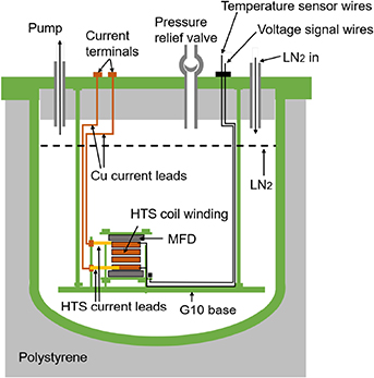
Figure 4. Schematic drawing of measurement set-up.
Download figure:
Standard image High-resolution image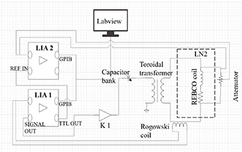
Figure 5. Schematic circuit diagram of measurement system.
Download figure:
Standard image High-resolution imageTwo lock-in amplifiers are used for the measurement: one for measuring the current amplitude and phase; the other for measuring the in-phase (with regard to the coil current phase) voltage of the coil assembly. A Rogowski coil (see figure 5) was used as the phase reference. The internal oscillator of one of the lock-in amplifiers supplies a sinusoidal signal to a CROWN K1 audio amplifier. The amplified sinusoidal voltage signal from CROWN K1 powers the primary winding of a toroidal transformer. The output of the secondary winding is used for energising the REBCO DPCs coil assembly immersed in liquid nitrogen at 1 atm. A capacitor bank was connected to the primary winding of the toroidal transformer for impedance matching.
The transport AC loss per cycle in a REBCO coil assembly with and without MFDs can be given as [30]:
where  is the rms current in the REBCO coil assembly,
  is the rms value of the in-phase voltage from the voltage taps attached in the ends of the coil assembly, and
  is the frequency of the coil current. It is worth noting that the measured data include AC loss both in the coil assembly and the MFDs, and the measurement cannot separate the loss contributions of the HTS coil assembly and the MFDs.
3. Numerical method
3.1. Homogenized 2D axisymmetric model based on H-formulation
An axisymmetric 2D FEM model based on H-formulation was built to simulate the magnetic field distribution and transport AC loss in the REBCO coil assembly. The MFDs are positioned near the top and bottom parts of the coil assembly and the distance between the assembly and the MFDs, d, can be varied. In order to reduce the computing time, the homogenization method [40] and structured mesh [41] are used in the FEM models. The upper half cross-section in figure 6 shows the homogenized sub-blocks of the REBCO DPCs and the structured meshes. Each DPC was divided into 40 axial elements and 6 radial sub-blocks. Each MPP MFD is divided into 20 axial elements and 30 radial elements.

Figure 6. Structured meshes of the REBCO coil assembly and the MFDs (only upper half cross-section is shown).
Download figure:
Standard image High-resolution imageThe E-J power law [42] in equation (2) is used in the FEM model to simulate the electromagnetic behaviours of the REBCO assembly.
where Ec
=  ,
ε
and
J
are the electrical field and current density of the REBCO tapes, respectively. n is the power-law exponent of the E-J curve which is set as 25 in this model. The modified Kim model [36] in equation (3) is used to represent the Jc
(B) dependence of the REBCO tapes.
,
ε
and
J
are the electrical field and current density of the REBCO tapes, respectively. n is the power-law exponent of the E-J curve which is set as 25 in this model. The modified Kim model [36] in equation (3) is used to represent the Jc
(B) dependence of the REBCO tapes.
where k, α, and B0 are the constants which are determined by critical current measurement under magnetic field. In this case, k = 0.43, α = 0.23 and β0 = 37 mT. B∥ is the magnetic field component parallel to the tape surface while B⊥ is the magnetic field component perpendicular to the tape surface. In this numerical model, B⊥ and B∥ are Br and Bz , respectively.
In this numerical model, the relative permeability  is used in the REBCO assembly and air domain. The
  of the flux diverters used in this model is from the B-H curve of 'Alloy Powder Core MPP 125' in COMSOL Multiphysics which is shown in figure 7. We experimentally confirmed the
  of MPP 125 at 77 K has the same value as at room temperature.
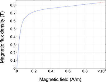
Figure 7. B-H curve of MPP 125 MFDs used in the numerical models.
Download figure:
Standard image High-resolution image3.2. Calculation of total AC loss
The AC loss  in the superconducting coil winding was calculated from equation (4).
where,  is the volume of the superconducting domain. The eddy current in stabiliser layers is not considered in this model.
The AC loss in MFDs consists of eddy current loss and hysteresis loss. The loss density of the MFDs was measured at 720 and 780 Hz using a conventional toroidal set-up method. A N4L PPA5530 precision power analyser was used for measurement. An MFD with the same dimension as the MFD used in the coil experiments was used. Figure 8 shows the measured Q-B relationship. The frequency-independent loss measurement results confirm hysteretic nature of the AC loss in the MPP MFDs. Eddy current loss can be ignored due to the very high resistivity in the material. AC loss in the MFDs, QMFD at different coil currents was calculated using the calculated distribution of peak flux density in the MFDs by interpolating the measured Q-B relationship shown in figure 8. It should be noted that the field configuration and eddy current geometry in the toroidal winding configuration described is not the same as that in the experimental setup with the HTS coils.
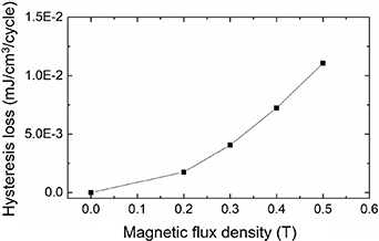
Figure 8. Measured AC loss of the MPP 125 as a function of peak magnetic flux density. Interpolation of this curve is used in the numerical model for calculating the loss in MFDs.
Download figure:
Standard image High-resolution imageThe summation of QSC and QMFD gives the total loss in the REBCO coil assembly with MFDs.
4. Results and discussion
4.1. Experimental results
The measured E-I curves of the REBCO coil assembly without MFDs and with MFDs at different d values are plotted together in figure 9. Ic values of the coil assembly before placing MFDs and after placing MFDs with d = 8 mm, 5 mm, and 2 mm at 77 K are compared. The measured coil Ic values are 51.6 A, 52.4 A, 53.4 A and 55.4 A, respectively. 1 µV cm−1 was taken as the voltage criterion for the coil Ic values. The Ic value is the smallest without MFDs and increases with decreasing d values. This can be explained by the numerical results shown in the numerical results section.

Figure 9. Measured E-I curves of the coil assembly without MFDs and with MFDs at different d values. Here WOMFD means without magnetic flux diverters.
Download figure:
Standard image High-resolution imageIn figure 10, the measured AC loss values per cycle at three frequencies in the REBCO coil assembly without MFDs, and with MFDs with different d values are plotted as a function of the coil current amplitude. The measurement results in the coil assembly with and without the MFDs at different frequencies agree well from one another. The result indicates the hysteresis nature of the loss characteristic. It should be noted that the measured values are total AC loss in the REBCO coil assembly and the MFDs. There will be difference in the measured AC loss values for different frequencies if there is any loss contribution due to eddy current in the MPP MFDs. There is some scatter in the measured loss values for d = 2 mm. We attribute the result to a lower S/N (signal to noise ratio) than other gaps due to the smaller loss voltage levels.
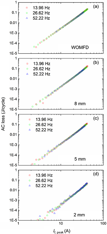
Figure 10. AC loss at different frequencies in the coil assembly with and without MFDs. Here WOMFD means without magnetic flux diverters. (a) Without MFDs, (b) with MFDs at d = 8 mm, (c) with MFDs at d = 5 mm, (d) with MFDs at d = 2 mm.
Download figure:
Standard image High-resolution imageFigure 11 compares the induced voltage from a single-turn pick-up coil attached on the surface of the upper half of the top DPC in the coil assembly without MFDs and with MFDs (d = 2 mm) at It
, rms
= 10, 15, and 20 A. The rectangular pick-up coil has a dimension of  . The voltage in the pick-up coil is induced due to the time-varying radial magnetic field component and the value of the voltage is proportional to the amplitude of the radial component. The induced voltage for the coil assembly after adding MFDs is significantly reduced compared to that without MFD. At 20 A (rms), the voltage from the assembly with MFDs is approximately 1/3 of that without MFDs. In REBCO coil assemblies, most of AC loss is caused by the radial field (which is perpendicular to the REBCO tape surface) in the end windings [31, 32]. The results in figure 11 directly show the effectiveness of MFDs for supressing the radial field component and hence reducing the AC loss in the coil assembly.
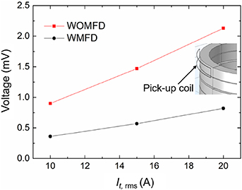
Figure 11. Induced voltages in the pick-up coil at three different currents at 52.22 Hz. The one-turn pick-up coil is attached on the upper half of the top DPC.
Download figure:
Standard image High-resolution imageIn figure 12, the measured AC loss results per cycle in the coil assembly without MFDs, with MFDs at three d values are plotted as a function of the coil current amplitude at three frequencies. It is apparent that AC loss in the coil assembly is reduced by the MFDs and it decreases with decreasing d values at all three frequencies. At It , peak = 30 A (around 60% of the coil Ic ) and f = 13.96 Hz, the AC loss value in the REBCO coil assembly without MFDs is 0.074 J/cycle. After placing MFDs with d = 2 mm, the total AC loss in the coil assembly and MFDs was reduced to 0.015 J cycle−1, i.e. the total AC loss was reduced by 80%. Such a significant AC loss reduction in REBCO coil windings using MFDs has not been reported in previous experimental works. The measurements at the other two frequencies show almost the same results. This unprecedented AC loss reduction may be attributed to the utilisation of low-loss MPP-125 MFDs. Other types of MFDs ferromagnetic materials such as Ni alloy could generate substantial loss in the material themselves although they could reduce AC loss in the REBCO coil windings. However, MPP-125 MFDs have negligible AC loss (as discussed in the following section) compared with the AC loss in the REBCO coil winding. One drawback of the MPP-125 MFD is that it has relatively low saturation field (0.8 T). However, MFDs do not necessarily form part of the main magnetic circuit in actual applications and hence could avoid large magnetic fields. E.g. in HTS transformers, the main circuit is formed through the iron core which couples with HTS coil windings but the MFDs are arranged near the top and bottom of the windings and hence experience a weaker magnetic field [33]. Therefore, a saturation field of 0.8 T might be sufficient for most situations.

Figure 12. Measured AC loss results in the coil assembly without MFDs, with MFDs at three d values at three frequencies. (a) 13.96 Hz, (b) 26.62 Hz, and (c) 52.22 Hz.
Download figure:
Standard image High-resolution imageIn figure 13, the AC loss reduction rate of the coil assembly with MFDs with three d values at different current amplitudes are compared. Compared with the AC loss in the REBCO coil assembly without MFDs, the average AC loss reduction with MFDs at d = 8, 5, and 2 mm are 36%, 51%, and 83%, respectively. The AC loss reduction rate increases with decreasing d value. The result suggests that MFDs should be placed as close as possible to the HTS winding in order to achieve larger loss reduction ratio in the HTS coil winding.

Figure 13. AC loss reduction rate verses the operating current at different d values.
Download figure:
Standard image High-resolution image4.2. Numerical results
Figures 14(a) and (b) show magnetic field lines and the radial magnetic flux density distribution in the upper half cross-section of the coil winding with and without MFDs and at f= 26.62 Hz, It , peak = 30 A, and d= 2 mm (for the case with MFDs). The flux lines in the top DPC in the coil winding with MFDs become more parallel to the REBCO tape surface (figure 14(b)) compared with the result without MFDs (figure 14(a)). The area filled with large radial field component and the amplitude of the radial field component in the REBCO DPCs for the case without MFDs are much larger than the result with MFDs. The maximum radial field component in the top DPC without MFDs is 0.1 T while the maximum radial field in the top DPC is reduced to 0.05 T with MFDs. Apparently, the difference observed in the above comes from the presence of the flux diverters. On the other hand, the MFDs have large area with high magnetic field concentration as shown in figure 14(b). The results shown in figure 14 clearly explain why the Ic values of the coil assemblies with MFDs shown in figure 9 are larger than that without MFDs.

Figure 14. Magnetic flux lines and radial magnetic flux density component distribution in the upper half cross-section of the coil winding with/without MPP MFDs ( f = 26.62 Hz, d = 2 mm with MFDs) at ¾ T (period); (a) without MFDs and (b) with MFDs.
Download figure:
Standard image High-resolution imageIn figure 15, the current density distribution in the REBCO DPCs with and without MFDs are compared. Shielding currents induced by the radial magnetic field components are observed in most of the pancake coils except the innermost pancake coil. However, with MFDs, the high current density area (|J/Jc | > 1) in the EWs is reduced remarkably compared with the case without MFDs. In figure 15(b), with MFDs, as most AC loss is generated in the area of |J/Jc | ≥ 1, the reduced area of high |J/Jc | indicates that AC loss reduction is achieved in the EWs. These results mentioned above demonstrate why AC loss in the REBCO coil winding is reduced by the use of MFDs.
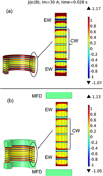
Figure 15. Distribution of current density with/without MFDs around the coil assembly (f = 26.62 Hz, d = 2 mm with MFDs) at ¾ T (period); (a) without MFDs and (b) with MFDs.
Download figure:
Standard image High-resolution imageFigure 16 compares the experimentally and numerically obtained total AC loss results in the REBCO coil winding without MFDs and with MFDs with d = 2 mm at 26.62 Hz. A good agreement was obtained between the numerical and experimental results.
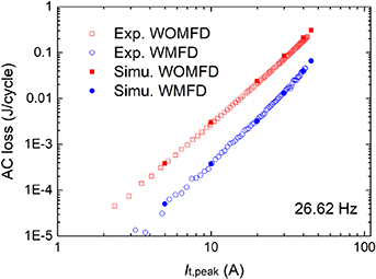
Figure 16. Comparison of the experimentally and numerically obtained total AC loss results at 26.62 Hz. WOMFD means without magnetic flux diverters while WMFD means with magnetic flux diverters. Here d = 2 mm.
Download figure:
Standard image High-resolution imageFigure 17 compares the simulated loss components in the REBCO coil winding with MFDs (d = 2 and 8 mm) at 26.62 Hz. It is apparent that AC loss in the MFDs is more than three orders of magnitude smaller than the AC loss in the HTS winding at It , peak = 45 A and the AC loss in the flux diverters can be ignored. Therefore, total AC loss in the coil assembly with the MFDs is dominated by the AC loss in the HTS windings. Nonetheless the increase of AC loss in the MFDs with decreasing d can be observed due to the increase of the magnetic field inside the MFDs. At both d values, AC loss in the EWs is much greater than that in the CW, and hence AC loss in the EWs dominates AC loss in the HTS winding. Interestingly, with d value varying from 8 to 2 mm, not only AC loss in the EWs becomes smaller but so does that in the CW. However, the change in the AC loss in EWs is much greater than that in the CW. The result at 2 mm indicates that there remains capacity to reduce total AC loss by making the d value smaller, bringing the loss-level of the EWs closer to the loss-level of the CW. However, the d cannot be reduced to 0 mm considering the insulation separation between the MFDs and HTS coil windings required for practical applications.
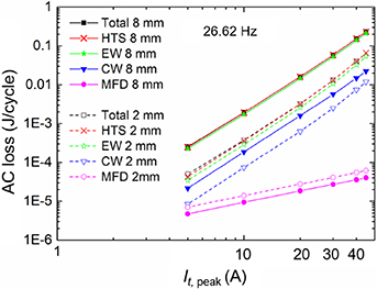
Figure 17. Comparison between simulated AC loss values at different part of the coil assembly for d = 2 mm and d = 8 mm at 26.62 Hz. Total, HTS, EW, CW, and MFD denote the loss values of the HTS coil assembly and MFDs, the whole coil assembly, the end windings, the centre winding, and the magnetic flux diverters, respectively.
Download figure:
Standard image High-resolution imageAs evident from the results in figure 15(b), there is still room for further reducing the AC loss in the double pancake coils next to the end windings. With the shape of the flux diverters described in this work, there is an obvious limit for further reducing the distance between the DPCs and the flux diverters and hence further reduce AC loss for double pancake coils next to the end windings. The limit becomes more obvious for more complicated coil windings comprising stacks of double pancake coils, because influence of the flux diverters can hardly reach DP2 and DP3 (see figure 18(a)) which can also be source of non-negligible AC loss. For coil windings stacked with large number of double pancake coils, combination of flux diverters for the end windings and some of double pancake coils nearby the end windings might be effective for minimising AC loss as shown in figure 18(b). Same strategy of AC loss reduction utilising flux diverters might be applied to hybrid coil windings comprising REBCO double pancake coils as end windings and Bi-2223 pancake coils as centre windings [6]. For 3-phase transformers, AC loss is more concentrated in the very end part of the high voltage and low voltage windings than stand-alone coil windings [32]. Therefore, flux diverters placed near the end windings might suffice for transformer applications.

Figure 18. Coil windings stacked with large number of double pancake coils (a) Flux diverters are only attached near the end windings, (b) flux diverters are attached near the end windings and some of double pancake coils near the end windings.
Download figure:
Standard image High-resolution image
5. Conclusion
In this work, we have experimentally and numerically investigated AC loss reduction in a REBCO coil assembly comprising four double pancake coils utilising low-loss MPP-125 MFDs attached near the top and bottom of the coil assembly. The frequency of the AC coil current and the distance between the coil assembly and the MFDs, d, were varied to investigate the influence of those parameters on AC loss reduction.
The lack of frequency dependence in the experimental results confirm the hysteretic nature of AC loss characteristics in the coil assembly and the MFDs. Both experimental and numerical results demonstrate effective AC loss reduction in the coil assembly with the MFDs compared to the assembly without flux diverters. The total AC loss in the coil assembly with the diverters decreases with decreasing d. The measured data in the coil assembly with the flux diverters shows 80% AC loss reduction at d = 2 mm compared with the AC loss data in the coil assembly without flux diverters. Such a high AC loss reduction has not been demonstrated in any previous experimental works.
Numerical simulation reveals that the AC loss reduction in the coil assembly is mainly due to the reduction of the radial field component in the EWs and negligible self-loss in the MPP MFDs. The result suggests that using low-loss ferromagnetic materials in flux diverters and reducing d are two critical ingredients for AC loss reduction in REBCO coils.
The results obtained in this work have practical implications for the design of HTS transformers.
Acknowledgments
This work was supported by the New Zealand Ministry of Business, Innovation and Employment Contract No. RTVU1707. SY thanks Yueming Sun for measurement system adjustment.