

Abstract
The screening current induced in superconductors can passively shield external magnetic fields and hence provide a noise free environment for precision sensors and instruments. This paper presents a novel design employing artificial joint-free REBCO (REBa2Cu3O7-x, RE: rare earths) coils which can economically extend the field shielding space for larger instruments, e.g. clinical equipment. We compared the shielding factors of single, double and multi-coils, and confirmed a coil with Helmholtz construction as the optimal architecture. Due to the zero resistance of the joint-free REBCO coils, the shielding effectiveness reaches 80 dB at the center of coils, shielding 99.99% of the external magnetic field of 10 μT at 1 × 10⁻⁵ Hz, and 40 dB (99%) in a greater spherical space of 40 mm in diameter. Additionally, the shielding effectiveness does not decrease in the external magnetic field of 1 nT. Such a low frequency magnetic shielding effect implies promising applications for the present work, such as preventing interference magnetic fields from precision instruments, which generally require field sensitivity as low as the fT · Hz−1/2 range.
Export citation and abstract BibTeX RIS
1. Introduction
Electronic devices for medical equipment and scientific measurements are becoming more and more delicate, and are extremely sensitive to background magnetic fields. Sensors, flux gate sensor, superconducting quantum interference devices (SQUIDs), and optical-pumping magnetometers for example, are sensitive to magnetic fields down to the fT · Hz1/2 range [1–6]. Therefore, magnetic shielding technology is essential to protect these sensors from noise interference.
Electromagnetic shielding technology can be generally divided into two categories: active shielding and passive shielding. In the principle of active shielding, magnetic fields are generated and controlled by compensation coils and feedback systems to cancel the background field [7, 8]. Therefore, the accuracy and response speed of active shielding is highly dependent on the control system and hence quite limited, unsuitable for middle and high frequency magnetic field shielding applications. Passive magnetic shielding systems usually consist of low resistivity conductors. The external field will induce eddy currents in the conductor which spontaneously screen out the external field [9–11]. However, the shielding field generated by the screening current is highly dependent on the frequency of the external field, and hence not available for DC and low frequency background fields.
In recent years, some new materials and technologies have been used in magnetic shielding [12–15]. Superconductors, possessing zero-resistivity and the Messner effect, provide powerful solutions for passive magnetic shielding. Superconducting magnetic shielding is effective for a wide range of frequencies. However, a superconducting ring with large inner radius can only shield part of an external magnetic field at the center point of ring. To solve this problem, Chen Gu's group reported [16] that concentric placed coils using Bi-2223(Bi2Sr2Ca2Cu3Ox) combined with REBCO (REBa2Cu3O7-x, RE: rare earths) tapes [17, 18], winding with two different radii, was able to improve the shielding effectiveness. The shielding effectiveness of the above coil was up to 55 dB in a 10 μT external magnetic field at 1 Hz-10 000 Hz. However, the shielding effectiveness reduced when the field frequency was lower than 1 Hz, which is 40 dB at 0.1 Hz and about 25 dB at 0.01 Hz. This was because the high temperature superconductor (HTS) coils have a low resistance induced by the joint between the inner and outer coils. In low frequency magnetic fields, the induced electromotive force of the coils is low, so that the existence of resistance will significantly reduce the induced current. In other words, it will reduce the reversing induced magnetic field.
REBCO coated conductors are advanced materials with great application prospects due to the high superconducting critical temperature and large in-field current carrying capacity [19, 20]. Recently a single turn coil without joint resistance which was made of single splitting REBCO tape, was proposed as a new type of trapped field magnet [21–24]. However, the shielding effectiveness of a single turn coil is not good enough. To improve the shielding effectiveness, it is necessary to add turns to the coil, and connect them in series without joints. In the present work, a new architecture using REBCO joint-free, multi-turn coils connected in series is designed, which can improve the shielding effectiveness, especially in extremely low frequency fields.
2. Modelling of shielding coils
2.1. Topology of the joint-free REBCO coils
Below, we will address the details for the artificial design. Two coils were placed concentrically using REBCO tape without any joint resistance, built with a special cutting method. The joint-free coil consists of an inner coil and outer coil, with the inner radius r1 and turn number n1 for the inner coil and the outer radius r2 and turn number n2 for the outer coil. The inner coil is closer to the center shielding position, and contributes more induced magnetic field to the center reference point. However, the induced current of the inner coil is not high enough, because its induction area of magnetic flux is relatively small.
To solve the problem, a winding method was designed, i.e. connecting the inner coil and the outer coil using single slitting REBCO tape without joint resistance. Since the outer coil exhibits a larger induction area, in the shielding process, it could provide extra electric potential to drive the inner coil, so that the inner coil obtains larger current and reversing magnetic field, as well as the enhanced shielding effect, which is significantly practical for precision sensors.
The ring shaped coils, as shown in figure 1, are prepared by cutting and splitting a piece of 4.5 mm wide REBCO long tape from the center, the width of the gap is 0.5 mm. It is possible to obtain a multi-turn coil by stacking these unfolded tapes concentrically as reported in [23]. We firstly calculated a two coil system as shown in figure 1(a). The radius is 70 mm for the inner coil and 180 mm for the outer coil made from REBCO tapes of 250 mm and 600 mm in length, respectively. The shielding area is inside the inner coil. We name this topology as Coil 1/1 where two coils are independent.
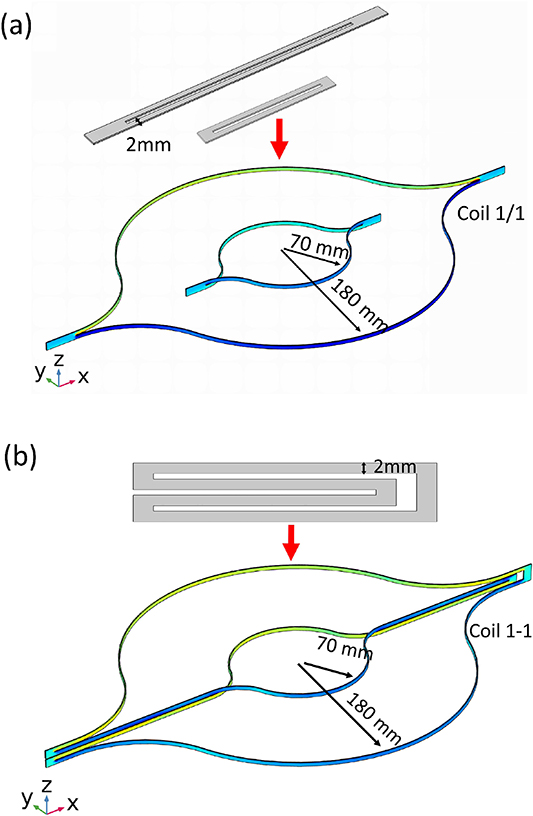
Figure 1. (a) The construction of the concentric placed ring-shape REBCO coil (coil 1/1). (b) The construction of the REBCO coil with two turns connected in series (coil 1–1).
Download figure:
Standard image High-resolution imageFigure 1(b) illustrates an improved topology by cutting the tape in a designed pattern. In this case, the inner and outer coil, when unfolded following the way shown in the figure, are connected in series without any joint as well. The resultant artificial coil is named as Coil 1–1 to distinguish it from coil 1/1 mentioned above. The radius of the inner (r1) and outer coils (r2) are 70 mm and 180 mm, respectively as well. This coil can be further extended to a 4-turn (Coil 2–2) or 6-turn coil (Coil 3–3) as shown in figure 2, if the REBCO tape is wide enough to enhance the shielding effect.

Figure 2. (a) The construction of the REBCO coil with four turns connected in series (Coil 2–2). (b) The construction of the REBCO coil with six turns connected in series (Coil 3–3).
Download figure:
Standard image High-resolution image2.2. Finite element model
The shielding effect was simulated numerically using the H-formulation combined with the E-J nonlinear relationship of REBCO coated conductors. The simulation was performed using COMSOL Multiphysics FEM software. We use the field dependant critical current density, Jc( ,
, ) formula reported in [25–28].
Faraday's Law (1) and Ampère's Law (2) are used as the governing equations:

The E–J power law is used to describe the nonlinear resistivity of the high temperature superconductor:
The critical electrical field Ec is set equal to 1 µV cm−1, the exponent n = 38 in the power law is used to describe how abrupt the transition from the superconducting to the normal state is. The in-field critical current density, Jc(B) use the following.
The parameters B0, k, and α are used to describe the relation between magnetic field and in-field critical current density Jc(B), and have the respective values of 42.6 mT, 0.295 and 0.7, where  and
and  are the parallel component and perpendicular component of the magnetic field to the surface of REBCO tape, and Jc0 is the critical current density of REBCO in self-fields, as the self-field critical current Ic0 of the REBCO tape is 40 A per millimeter in width, at 77 K.
The models were built using COMSOL Multiphysics. In geometric modeling, the length and width of REBCO tape is in the millimeter range, however the thickness of REBCO superconducting layer is as low as 1 μm, which is much smaller than the length and width. The large ratio between length (width) and thickness will increase the difficulty of calculation. To solve this problem, the REBCO layer with 1 μm thickness can be equivalently transformed to REBCO tape with 0.3 mm thickness including both substrate and covering layer.
The self-field critical current Ic0 of the REBCO tape is fixed at 40 A per millimeter in width, so the critical current density of the 1 μm thick REBCO layer is 4 × 10¹⁰ A m−2. Since the thickness of the total REBCO tape is 0.3 mm, in modeling, the tape is assumed to be made of 0.3 mm thick REBCO layer only. According to the thickness ratio of 0.3 mm to 1 μm, the critical current density Jc0 of the total tape can be set as 1.33 × 10⁸ A m−2, the current density J and in-field critical current density Jc(B) are equivalently transformed as well.
Meanwhile, considering the thin thickness of REBCO film, the mesh of tape should be built in only a single layer in the REBCO c axial direction (perpendicular to the surface of tape), as figure 3 shows. In the thickness direction, the size of each mesh is 0.3 mm, the same as the thickness of the tape. In the width direction of the tape, the 4.5 mm width was divided into 45 parts, the size of each mesh is 0.1 mm. In the length direction of tape, the size of each mesh is 0.5 mm–1 mm.

Figure 3. Model meshing of REBCO coil with single layer method.
Download figure:
Standard image High-resolution image2.3. Shielding effectiveness
A magnetic field of 10 μT at 1 × 10⁻⁵ Hz was applied along the axial direction of the coil via the Dirichlet boundary condition to test the shielding effect. The external field will induce a screening current in the persistent REBCO coil which generates a reversing magnetic field to shield part of the external field. We define the shielding factor (SF) at the testing point as the specific value, which is the ratio between the resulting field Br over the external field B0, SF = (Br/B0)× 100%. And therefore, a small SF value indicates a better shielding effect.
Figure 4(a) shows the magnetic intensity at the center of the shielding coils with different topologies. In all of the four models, r1 is 70 mm and r2 is 180 mm. The time-dependent applied field of 10 μT at 1 × 10⁻⁵ Hz was plotted with dashed lines. The shielding factors are compared in figure 4(b). It can be observed that the central field of Coil 1–1 is lower than Coil 1/1, which indicates the shielding effectiveness of coils with series connection is better than coils that are placed independently. The shielding effectiveness improves when comparing Coil 1–1, Coil 2–2 and Coil 3–3, with increasing number of turns, the peak resultant field at the central point of Coil 3–3 is 20 nT, which provides the best shielding effect.

Figure 4. (a) Axial direction (z direction) external field and resulted field intensity in the center point of shielding coils depend on time. (b) Shielding factor comparison of the four types of coils.
Download figure:
Standard image High-resolution imageIn the model, when r1 is fixed as 70 mm, the shielding effectiveness then depends on the size of the outer radius (r2). Figure 5 shows the shielding factor of Coil 1–1 at the center point with different r2 values. It reveals that the shielding factor decreases when r2 increases, which means that the larger induction area leads to greater induced reversing field. In addition, when r2 is larger than 300 mm, the shielding factor turns negative, because the induced reversing field becomes larger than the external field. r2 = 300 mm can make the shielding factor be nearly zero. Since too large a radius of outer coil would take up much space and increase the volume of the shielding system, r2 = 300 mm is not an economical choice. In this way, r2 can be selected as 180 mm, in order to improve the shielding effectiveness by addingturns of coil and may then be effective and space-saving, as demonstrated by Coil 2–2 and Coil 3–3.

Figure 5. With r1= 70 mm, shielding factor of Coil 1–1 at the center point with different r2 value.
Download figure:
Standard image High-resolution imageIn applications, the size of the shielding space is of great importance. Figure 6 shows the shielding factor along the z-direction (a) and x-direction (b), as well the magnetic field distribution in the x-z plane (c) and x-y plane (d) for Coil 3–3, which shows the best shielding effect at the center of the coil. The tested space is a 50 mm diameter of spherical volume (DSV). This size of space is considered meaningful for practical applications.
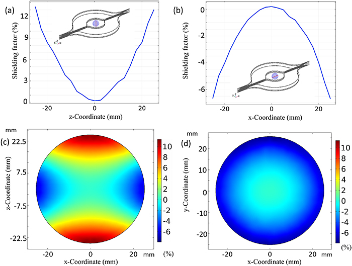
Figure 6. Distribution of shielding factor in the 50 mm DSV of Coil 3–3. (a) Shielding factor distribution along z = − 25 mm to z = 25 mm (x = 0, y = 0). (b) Shielding factor distribution along x = − 25 mm to x = 25 mm (y = 0, z = 0). (c) Shielding factor distribution in the x-z plane, with y = 0. (d) Shielding factor distribution in the x-y plane, with z = 0.
Download figure:
Standard image High-resolution imageAt the center of coil 3–3, the shielding factor is the lowest of 0.2%, and increases along the z-direction, decreasing to negative along the x-direction as shown in figures 6(a) and (b), respectively. In the x-y plane (figure 6(d)) of the shielding area, the size of 1% shielding factor area reaches 20 mm in diameter. However, in the z direction of the x-z plane (figure 6(c)), the size of 1% shielding factor area is less than 10 mm. Moreover, it is observed that the shielding factor increases to 13% 25 mm away from the center of coil 3–3. Therefore the size of the 1% shielding factor zone in the axial direction (z direction) is narrow. Interestingly, there exists a negative shielding factor in some areas, where the reversing induced field of coil is greater than the external field. A negative shielding factor means over shielding. It implies an excess of coil turns may give rise to a negative shielding effect.
3. Optimization of shielding effectiveness with Helmholtz construction
3.1. Optimization of distance between two identical 2-2 coils, and 3-3 coils
To achieve larger available shielding space with 99% shielding factor, especially along the axial direction, a Helmholtz coil is designed, which is believed to be an effective way to improve the uniformity of shielding field. In the present work, a Helmholtz coil consists of double Coil 2–2 is built (namely Coil 2–2AB), also another Helmholtz coil consisting of double Coil 3–3 (namely Coil 3–3 A'B') is built, as shown in figure 7. Generally, for the Helmholtz coil, the distance between two identical coils is the same as the radius of coil. Considering the shielding effectiveness optimization and over shielding effect that occurred, as mentioned above, it is necessary to optimize the distance between coil A and coil B in Coil 2–2AB, also between coil A' and B' in Coil 3–3 A'B'.

Figure 7. (a) The Helmholtz coil consists of two Coil 2–2, namely Coil 2–2AB. (b) The Helmholtz coil consists of two Coil 3–3, namely Coil 3–3 A'B'.
Download figure:
Standard image High-resolution imageFigure 8 shows the shielding factor in the center of Coil 2–2AB and Coil 3–3 A'B' with different distance. It reveals that the value of shielding factor increases linearly with the distance increasing from 70 mm to 120 mm. In Coil 2–2AB, while the distance is less than 85.78 mm, the value of shielding factor is negative, suggesting that too much of over shielding should be avoided. As the distance is greater than 85.78 mm, the shielding factor increases from 0.01% to more than 7.4%. The applicable distance between Coil A and Coil B appears to be 85.78 mm, while the shielding factor reaches 0.01%. For Coil 3–3 A'B', the shielding factor is negative if the distance is less than 115 mm. This indicates that the reversing induced magnetic field is too strong, and leads to strong over shielding effect which should be avoided. When the distance is 115 mm, the shielding factor of Coil 3–3 A'B' become close to 0, but it will waste more space for the shielding coil in the axial direction and needs wider superconducting tape than Coil 2–2AB. Therefore, Coil 2–2AB is more applicable for magnetic shielding than Coil 3–3 A'B'.

Figure 8. Shielding factor in the center of coil 2–2AB and Coil 3–3 A'B', with different distance between coil A and coil B (coil A' and coil B').
Download figure:
Standard image High-resolution image3.2. Shielding factor distribution
We further investigate into the spatial distributions of the shielding factor as figure 9 exhibits, in the 70 mm diameter of spherical volume (DSV) at the center of Coil 2–2AB, the optimized distance between Coil A and Coil B is selected as 85.78 mm. Compared with Coil 3–3, the minimum shielding factor of Coil 2–2AB is much lower. Moreover, the size of 1% shielding factor space of Coil 2–2AB is much larger than that of Coil 3–3. Obviously, the shielding factor along the z-direction is much optimized, which is less than 1% along −35 mm to 35 mm (x = 0, y = 0). In the x-y plane, the size of 1% shielding factor area is 40 mm (z = 0) in diameter. In the whole of the 40 mm DSV, the shielding factor is kept below 1%. In the whole of the 70 mm DSV, the shielding factor remains below 4%. Therefore, it is concluded that the design of Coil 2–2AB appears to have better shielding effectiveness than Coil 3–3.

Figure 9. Distribution of shielding factor in the 70 mm DSV of coil 2–2AB, the distance between coil A and coil B is 85.78 mm. (a) Shielding factor distribution along z = − 35 mm to z = 35 mm (x = 0, y = 0). (b) Shielding factor distribution along x = − 35 mm to x = 35 mm (y = 0, z = 0). (c) Shielding factor distribution in the x-z plane, with y = 0. (d) Shielding factor distribution in the x-y plane, with z = 0.
Download figure:
Standard image High-resolution image3.3. Shielding factor in different magnetic field intensity and frequency
The shielding factor of the fixed coil is concerned with the external field frequency and the coil resistance. For jointed coils, the shielding effectiveness will reduce in low frequency fields because of jointed resistance. Because the induced electromotive force of the coil is small in low frequency fields, the existence of resistance will significantly reduce the induced current. In other words, it will reduce the reversing induced magnetic field. Since the resistance of joint-free REBCO coil is nearly zero, theoretically speaking, the shielding effectiveness of joint-free coil will not decrease significantly in extremely low frequency magnetic fields. Compared with the report of Bi-2223 shielding coils jointed by YBCO tape with a little welding resistance [16], as figure 10(a) shows, in 10 μT varying external magnetic field, the shielding factor of joint-free coil without resistance (Coil 2–2AB) remains stable from 0.01 Hz to 1000 Hz. However, the shielding factor of jointed coil [16] increases significantly when the frequency is lower than 1 Hz. It indicates that the joint-free architecture is helpful to maintain the shielding effectiveness in low frequency fields.

Figure 10. Shielding factor in different external magnetic field amplitude and frequency. (a) Shielding factor of reported superconducting coil with joint, and shielding factor of Coil 2–2AB without joint, both of the external field amplitude is 10 μT. (b) Shielding factor of Coil 2–2AB in different external field frequency, the field amplitude is 1 mT and 1 nT.
Download figure:
Standard image High-resolution image
The external field intensity determines the induced current intensity of the coil. When the induced current intensity is close to the the critical current intensity of REBCO coil, according to the E-J nonlinear resistivity relationship of HTS, the resistance of coil will increase significantly, it will weaken the induced current, especially under low frequency. Then the shielding effectiveness will decrease (in other words, the shielding factor increases). As figure 10(b) shows, for joint-free coil, the shielding factor of Coil 2–2AB remains about 0.01% in a 1 nT external magnetic field from 1 × 10⁻⁵ Hz to 10 Hz, which means the resulting field is as low as the fT · Hz−1/2 range. But in a 1 mT external magnetic field, the shielding factor increases with the decrease of frequency. It indicates that if we need to shield higher magnetic fields, the current-carrying capability of superconducting coil should be improved, by using wider tape or more turns, for example.
4. Conclusion
In summary, the present work designed several joint-free REBCO coils and numerically investigated their shielding factor distributions with respect to the improvement of magnetic shielding effectiveness. In a 10 μT at 1 × 10⁻⁵ Hz applied magnetic field, the shielding factor of Coil 3–3 reaches 1%, in the shielding space of 10 mm DSV and 8.5% in the shielding space of 20 mm DSV. Helmholtz construction coils were also designed, by optimizing the distance between two identical 2–2 coils, A and B. The shielding factor of Coil 2–2AB reaches 1% in the shielding space of 40 mm DSV and 4% in the shielding space of 70 mm DSV. It is observed that the shielding effectiveness and shielding space of Coil 2–2AB is better than Coil 3–3. This is due to the intrinsic zero resistance of REBCO coated conductors and artificial joint-free design, meaing the shielding effectiveness can maintain a good performance in lower frequency fields, even in the magnetic field of 1 nT at 1 × 10⁻⁵ Hz. The joint-free REBCO coils are therefore able to shield external magnetic fields at the level of fT · Hz−1/2 .
The present shielding is able to remove the interference field on the sensors of precision instruments, such as flux-gate magnetometers, magnetoresistance magnetometers, SQUID gradiometers and optically pumped magnetometers, etc, which are extremely sensitive to low frequency and intensity magnetic noise. It is expected to be applied in the magnetic shielding of low field measurement, including magnetic resonance imaging, geomagnetic studies, as well as fundamental studies of weak magnetism. In addition, by tailoring the REBCO coil radius, the field shielding space can be economically extended for larger instruments, e.g. clinical equipment, to provide a large and open shielding space.
Acknowledgments
This work was supported by the Strategic Priority Research Program of the Chinese Academy of Sciences (CAS) Grant No. XDB25000000, the National Key R&D Program (2016YFF0101701), the National Natural Science Foundation of China (51572165), and the Science and Technology Commission of Shanghai Municipality (16521108400, 16DZ0504300 and 14521102800).
Data availability statement
The data that support the findings of this study are available from the corresponding author upon reasonable request.