
Abstract
We have directly measured, for the first time, the Nb3Sn and Cu loading strains and stresses in 11 T dipole coil segments upon compressive loading using neutron diffraction. For this purpose a load frame that enables rotation of the sample load axis with respect to the neutron scattering geometry was installed in the Stress-Spec beamline at the Heinz Maier-Leibnitz FRM II neutron source. The neutron diffraction data suggests that the magnet coil wound of Rutherford type cables can be considered as a fibre reinforced composite material. In the axial load direction the load is mainly carried by the Nb3Sn filaments and the composite stiffness can be estimated by the rule of mixtures assuming iso-strain conditions in all composite constituents. Under transverse compression the fully annealed Cu provides an isotropic pressure around the Nb3Sn filaments. The transverse load stresses in the Cu and Nb3Sn are similar, indicating iso-stress behaviour of the coil constituents under transverse compression. The broadening of the Nb3Sn diffraction peaks above critical stress values indicates reversible and irreversible Nb3Sn loading stress effects.
Export citation and abstract BibTeX RIS

Original content from this work may be used under the terms of the Creative Commons Attribution 4.0 licence. Any further distribution of this work must maintain attribution to the author(s) and the title of the work, journal citation and DOI.
1. Introduction
The mechanical stress exerted on the coils of superconducting magnets affects their ultimate performance limits. Reversible critical current (Ic) changes of Nb3Sn conductors are commonly ascribed to elastic lattice distortions [1–3]. When the externally applied load exceeds a critical value, crack formation in the Nb3Sn filaments causes an irreversible Ic degradation [4].
In solenoid magnets the Lorentz forces mainly cause a tensile stress in the axial conductor direction. The effect of uniaxial tensile loading on the superconductor strain state and superconducting properties has been studied extensively, and the strain state in composite wires and tapes and the load transfer among the different conductor constituents could be measured directly as a function of uniaxial tensile stress [5–9].
In order to keep coil inductance within acceptable limits, Nb3Sn accelerator magnet coils are wound using high current Rutherford type cables [10]. A cross section of the 11 T dipole coil made of Nb3Sn Rutherford cables is presented in figure 1. The void space between the electrically insulated cables is filled with an epoxy resin in order to improve the critical stress levels that the conductor can resist without an irreversible conductor degradation by filament breakage.

Figure 1. (a) Metallographic cross section of 11 T dipole coil with six conductor blocks with definition of transverse and radial directions. (b) Detailed view of a conductor block.
Download figure:
Standard image High-resolution imageIn accelerator magnets [11] like the Nb3Sn magnets presently build for the LHC High Luminosity upgrade (HL-LHC) [12], or those developed for the Future Circular Collider study, the dominant load case is transverse compressive loading. It is well known that transverse compressive stress can cause a strong degradation of the Nb3Sn superconducting properties [13]. When the macroscopic transverse compressive stress exerted at room temperature on a 11 T dipole Rutherford cable exceeds about 150 MPa the conductor is permanently degraded, presumably due to cracking of the brittle Nb3Sn filaments [14].
A detailed understanding of the stress–strain behaviour of the conductor blocks and their constituent materials under superconducting accelerator magnet assembly and operating conditions is required to better understand the degradation mechanisms, and to further optimise the conductor and magnet design. So far, the Nb3Sn strain and stress state evolution in magnet coils during application of an external load is not well known, and the stress–strain behaviour of conductor blocks has often been modelled using estimated average isotropic material properties [15].
State-of-the-art neutron scattering facilities like the Stress-Spec strain scanner at the FRM II neutron source [16] enable direct residual and applied strain measurements in accelerator coil segments. Previously we reported on residual Nb3Sn strain remaining in 11 T Nb3Sn dipole magnet coil segments after magnet cold testing and disassembly [17]. In this article we report, for the first time, on a direct measurement of the effect of externally applied transverse and axial compressive stress on the internal strain and stress state in the different composite coil constituents.
2. Experimental
2.1. The samples
The samples studied are stacks made of ten reacted Nb3Sn Rutherford cables used for the 11 T dipole coils (so-called ten-stack samples). The 11 T dipole cables with a nominal width of 14.7 mm and a mid-thickness of 1.25 mm, are stacked alternatingly in order to compensate for the keystone angle of 0.79° [10]. The Rutherford cables are made of 40 Restacked-Rod Process (RRP) type Nb3Sn strands from Oxford Instruments Superconducting Technology, now Bruker-OST. The Nb3Sn heat treatment was performed with a ramp rate of 50 °C h−1 and comprised three isothermal plateaus of 210 °C-48 h, 400 °C-48 h and 665 °C-75 h. The cables with a 25 μm thick stainless steel core are surrounded by a 0.15 mm thick cable insulation made of a mica tape and S2/E-glass fibre. A non-impregnated and an impregnated cable stack were used for the experiments in the transverse and axial load directions, respectively. The height of the non-impregnated and impregnated ten-stack samples was 16.6 mm and 15.6 mm, respectively. For more information about the samples see [18].
2.2. Loading strain measurements
Loading strains were measured at ambient temperature in situ under a neutron beam as a function of externally applied stress. Compressive stresses were applied either in the transverse or in the axial direction using a load frame combined with an Eulerian cradle that enables rotation of the sample load axis with respect to the scattering geometry (figure 2). The maximum force that can be applied with the load frame is 50 kN, corresponding to a maximum compressive stress of 220 MPa on the samples with a cross section of 225 mm2. The effect of friction on the stress–strain results was limited by adding lubricant (PTFE spray) on the sample to pressing tool contact surfaces. In order to limit buckling effects, the sample height does not exceed the sample width. Force measurements were performed with an HBM Type 03 50 kN load cell, and the sample strain was measured with an Instron 2620-602 extensometer with a gauge length of 13.1 mm (figure 2).
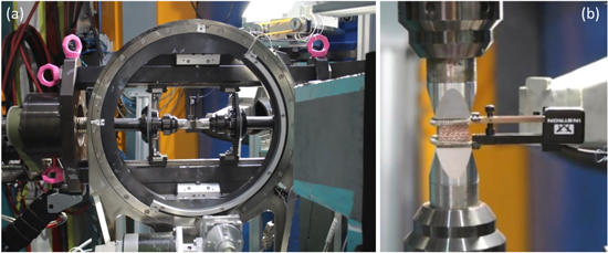
Figure 2. (a) Load frame mounted in Eulerian cradle in the Stress-Spec beamline in horizontal measurement position. (b) Nb3Sn Rutherford cable stack mounted for a compression test with the extensometer attached.
Download figure:
Standard image High-resolution imageAll experiments were started with a compressive preload of about −0.2 kN, corresponding with a pre-stress of about 1 MPa. Measurements were performed with applied stress steps of 15 MPa, and the load rate between the stress plateaus was always 50 N s−1.
A bent Si (400) monochromator provides a neutron beam with an approximate wavelength of λ = 1.672 Å. Lattice strain measurements were performed in the assumed principal stress directions, which are in the following referred to as axial, radial and transverse directions. The transverse direction corresponds to the azimuthal direction in a coil. A diffraction angle range 70.5° < 2Ɵ < 83.5° was recorded, and the Nb3Sn (321) and Cu (220) reflections were fitted by Gaussian functions. In addition to the pure Cu stabiliser, the reacted RRP type conductor contains α-bronze in the Nb3Sn subelement cores. Because of the Sn in solid solution the Cu lattice parameter of α-bronze is larger than the pure Cu lattice parameter, and both diffraction peaks could be distinguished in the experiment. Only the pure Cu diffraction peak has been fitted and taken into account in the elastic strain calculations.
Previous stress dependent synchrotron x-ray diffraction measurements where a large d-spacing range could be recorded [6] have shown that the Nb3Sn (321) reflection represents the overall Nb3Sn strain behaviour well. In face-centred cubic materials like Cu the effect of intergranular stresses on peak position is comparatively strong on (200) reflexes [19], therefore, these peaks have been avoided. Prior to peak fitting the diffractograms were corrected for the detector efficiency using incoherent scattering from a vanadium scan. The diffraction angles are an average inside the analysed gauge volume of nominally 5 × 5 × 5 mm3, which is defined by a 5 × 5 mm2 slit that shapes the beam and by a radial collimator in front of the detector. The acquisition time for the recording of the Nb3Sn (321), and Cu (220) diffraction peaks in the three directions is about 45 min per measurement point. The main Nb (100) peak is not present in this configuration (beam parallel to wire drawing axis) because of the strong Nb texture [20].
The Nb3Sn and Cu loading strains εhkl in the transverse, axial, and radial directions have been determined from the Nb3Sn (321) and Cu (220) scattering angles θhkl according to equation (1). The assumed stress free scattering angles are 2θ0_Nb3Sn(321) = 72.783° and 2θ0_Cu(220) = 81.937°.

2.3. Loading stress calculations
Loading stresses have been calculated according to equation (2), assuming that the transverse, axial and radial directions are the principal stress directions in the sample, and that there are no shear stresses. Nb3Sn (321) and Cu (220) elastic constants (Ehkl) and Poisson ratios (νhkl) have been calculated from single crystal elastic constants [21, 22] using the Kröner coupling model [23] for the interaction between crystallites (ENb3Sn(321) = 131 GPa, νNb3Sn(321) = 0.363,ECu(220) = 138.9 GPa, νCu(220) = 0.333).
3. Results
3.1. Transverse compression
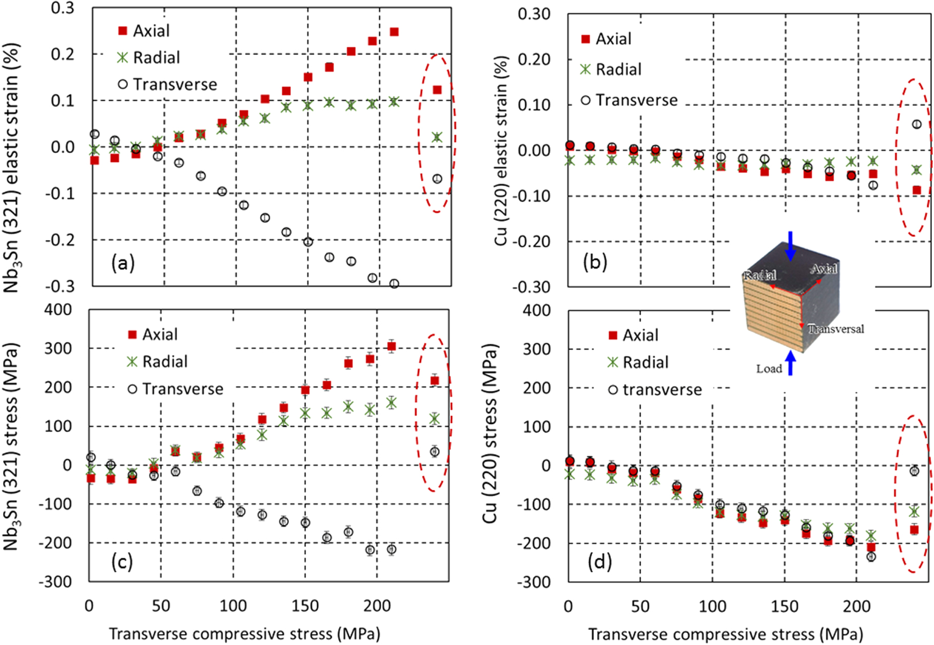
The evolution of the Nb3Sn and Cu loading strains and stresses in a non-impregnated 11 T dipole cable stack in the three principal directions are presented in figure 3. Before application of external stress, Nb3Sn is under slight axial compression and Cu under slight axial tension. This is the result of the thermal expansion mismatch of the different conductor constituents during cooling from the Nb3Sn processing temperature of 650 °C. Upon application of external transverse pressure, a similar compressive Cu loading stress evolution is observed in the three principal directions (figure 3(d)). The transverse Cu pressure in the axial and radial directions imposes an axial and radial tensile stress on the Nb3Sn filaments (figure 3(c)).

Figure 3. (a) Nb3Sn (321) and (b) Cu (220) loading strains and (c) Nb3Sn (321) and (d) Cu (220) stresses in non-impregnated 11 T dipole cable stack as a function of externally applied transverse compressive stress. Circled data points show the residual strain when the external stress is released.
Download figure:
Standard image High-resolution imageIn figure 4 the Nb3Sn and Cu loading stresses in the non-impregnated 11 T dipole cable stack are compared. In the transverse direction (i.e. the loading direction), the Nb3Sn and Cu stress evolutions are nearly identical, and the transverse stresses increase linearly with increasing external pressure. This indicates that the composite exhibits iso-stress behaviour when it is loaded perpendicularly to the filament (wire) direction. The Nb3Sn and Cu loading stress increase is about 20% higher than the external pressure increase. This difference can be partly explained by the presence of about 25% porosity in the sample that does carry load. When the external load is released the transverse Nb3Sn and Cu stresses are almost completely relaxed as well. In the radial direction Nb3Sn and Cu stresses have similar magnitude, Nb3Sn being in tension and Cu in compression. In the axial direction the higher Nb3Sn tensile stress with respect to the Cu compressive stress can be explained by a comparatively smaller Nb3Sn cross section with respect to the Cu cross section. When the external transverse pressure is released the axial and radial stresses are only partly released.
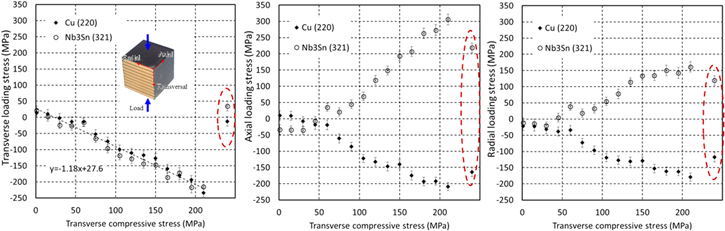
Figure 4. Comparison of Nb3Sn (321) and Cu (220) loading stress evolution in (a) transverse, (b) axial and (c) radial directions as a function of externally applied transverse compressive stress. Circled data points show the residual strain when the external stress is released.
Download figure:
Standard image High-resolution imageThe Nb3Sn loading stresses shown above are average values inside the gauge volume. The maximum Nb3Sn stresses are likely higher, as indicated by the Nb3Sn diffraction peak broadening when the external load is increased (figure 5). Nb3Sn diffraction peak broadening indicates that the strain inhomogeneity increases, which occurs first in the transverse and radial directions. When the external transverse pressure on the non-impregnated cable stack exceeds 130 MPa, Nb3Sn (321) peak broadening is also observed in the axial direction.
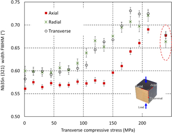
Figure 5. Nb3Sn (321) diffraction peak width evolution as a function of externally applied transverse compressive stress. Circled data points show the residual strain when the external stress is released.
Download figure:
Standard image High-resolution image3.2. Axial compression
Figure 6 presents the Nb3Sn and Cu loading stress evolution in an impregnated 11 T dipole cable stack under axial compressive loading. At 150 MPa externally applied axial pressure the axial Nb3Sn (321) and Cu (220) loading stresses are about 300 MPa and 100 MPa, respectively. This stress evolution is compatible with the assumption of iso-strain conditions when the conductor is loaded in the wire and Nb3Sn filament direction.

Figure 6. (a) Nb3Sn and (b) Cu loading stresses in an impregnated cable stack as a function of axial compressive stress. Circled data points show the residual strain when the external stress is released.
Download figure:
Standard image High-resolution imageThe assumption of iso-strain conditions is further confirmed by the comparison of the macroscopic sample strain measured with an extensometer, and the Nb3Sn filament strain determined from the Nb3Sn diffraction angles (figure 7(a)). Under axial loading the radial and transverse lattice parameter changes can be explained almost entirely by the Poisson effect (figure 7(b)).

Figure 7. (a) Elastic axial strain derived from neutron diffraction data as a function of the macroscopic axial sample strain measured with an extensometer. (b) Average transverse and radial Nb3Sn (321) strain as a function of axial strain.
Download figure:
Standard image High-resolution image
4. Discussion and conclusion
Thanks to the combined stress–strain and Nb3Sn filament and Cu matrix lattice parameter measurements, a detailed understanding of the stress–strain behaviour of the conductor blocks in superconducting accelerator magnets has been obtained. The neutron diffraction results suggest that the magnet coil wound of Rutherford type cables can be considered as a fibre reinforced composite material, which exhibits strongly anisotropic mechanical properties.
In the axial load direction, the coil block stress–strain behaviour can be predicted assuming iso-strain conditions in all composite constituents. This is consistent with the directly measured axial stiffness of an 11 T dipole cable stack of 94 GPa [18], and the stiffness calculated according to the rule of mixtures from the constituent E-moduli, Ewire = 126 GPa [24] and Eepoxy = 4 GPa.
In axial load direction the load is mainly carried by the Nb3Sn filaments because the annealed Cu cannot carry high loads (at 150 MPa externally applied axial pressure the axial Nb3Sn (321) loading stress is about 300 MPa).
Under transverse pressure the annealed Cu in the coil, which has a proof stress of Rp0.2 = 50 MPa [25], exhibits an isotropic compressive stress around the filaments. The transverse load stresses in the Cu and Nb3Sn are similar, indicating iso-stress behaviour of the coil constituents under transverse compression.
The results presented here are a new opportunity to validate finite element models and to simulate the mechanical and electromechanical behaviour of Nb3Sn accelerator magnet coils in more realistic conditions than has been possible so far. Under transverse compression the epoxy impregnation can reduce the Nb3Sn loading stresses. However, assuming iso-stress behaviour, the elastic properties of the impregnation material should not strongly influence the Nb3Sn coil stiffness.
The load case of transverse compression of unconstrained cable stacks is not fully representative for the mechanical loading in magnets, where the coils are constrained in the axial and radial directions. However, the three main results of this study, iso-strain conditions in axial load direction, iso-stress conditions in transverse compression and the isotropic compressive stress distribution in the annealed Cu, are valid for magnets too.
Acknowledgments
This work was supported by the European Commission under the FP7 project HiLumi LHC under Grant GA 284404, co-funded by the DoE, USA and KEK, Japan.
Part of this work is based upon experiments performed at the Stress-Spec instrument operated by FRM II at the Heinz Maier-Leibnitz Zentrum (MLZ), Garching, Germany.