
Abstract
Mechanical to electrical energy conversion is a well-established energy transduction approach. However, cases in which a mechanical energy source is not available call for new approaches to harvest electrical energy. In the present study, we demonstrate energy harvesting in soft dielectric elastomer (DE) tubes. Broadly, energy harvesting is obtained through inflation of the tube, electrical charging of the DE layer, and deflation, which results in a decrease in capacitance and an increase in voltage. We propose two methods to mechanically charge (or inflate) the system: (1) active, in which the tube is inflated through the application of mechanical pressure, and (2) passive, in which a passive cylindrical component placed inside the DE tube deforms radially in response to an environmental stimulus such as thermal excitation or water uptake and inflates the DE tube. To demonstrate passive charging, we consider gels as the passive component and employ well-known models with the properties of the commonly employed DE VHB 4910 to simulate the mechanical response of the system and estimate the harvested electrical energy. Our findings reveal that energy-densities in the order of ∼10–50 mJ cm–3 can be harvested. The proposed approach and the inclusion of a passive component to mechanically charge the system opens new opportunities to generate energy in environments lacking traditional mechanical energy sources.
Export citation and abstract BibTeX RIS

Original content from this work may be used under the terms of the Creative Commons Attribution 4.0 license. Any further distribution of this work must maintain attribution to the author(s) and the title of the work, journal citation and DOI.
1. Introduction
Many modern applications, in which human intervention is either impossible or requires significant amount of human labor and time, demands a reliable, durable, and constant supply of energy. Examples of such applications include remote sensing, control-based applications, and IOT [1, 2]. Energy harvesting devices are one of the commonly employed solutions to this problem. Typically, these self-powered systems comprise three parts: (1) a transducer/harvester, which converts ambient power into usable electrical energy, (2) a battery to store the harvested energy, and (3) the final user, which utilizes the energy [3]. The transducer can be based on different conversion methods such as electromechanical [4], electromagnetic [5], triboelectric [6], acoustoelectric [7], thermoelectric [8], photoelectric [9], and chemoelectric [10]. Among them, the electromechanical mechanism is of particular interest since it can harness the mechanical energy available in several environments, such as natural or artificial vibrations, fluid motion, etc.
Energy harvesting from mechanical inputs is a well-known technology that exploits mechanical to electrical conversion with various materials and technologies [11]. Commonly, piezoelectric materials are employed to perform this conversion. However, stimuli-responsive polymers represent an interesting alternative to traditional energy harvesting approaches. Dielectric elastomers (DEs), which can experience large deformations in response to electric excitation [12, 13], as well as gels, capable of huge volumetric deformations upon solvent absorption [14–16], are examples of such materials. Commonly, DEs have been used for energy storage and energy harvesting by harnessing energy conversion mechanisms [17–19]. However, in the literature no particular attention has been focused on the mechanical energy source necessary to deform the DE material. Often, mechanical energy coming from human motion [20, 21] or vibrations of the environment [22] have been considered as suitable sources to harvest energy by using dielectric materials. Coupling hydrogels with highly deformable DEs provides the opportunity to convert mechanical energy, generated as a result of environmental conditions, to electrical energy. Broadly, this process takes advantage of the geometric deformations of DEs and the consequent change in electric capacitance [23–28], resulting in small-scale structures with high energy-density. For example, in VHB-type materials the measured harvested energy-density is on the order of magnitude of ∼10 mJ cm–3 with an efficiency of ∼20% for planar actuation and harvesting modes [29–31]. The work of Jiang et al [32] reported to produce ∼130 mJ cm–3 with an efficiency of ∼25% with the same material under a cone configuration.
Extensive studies have been conducted to understand the key parameters that govern the response of DE-based energy harvesting devices [33–35]. In addition, works that investigate the influence of material parameters [36–39], instability, and dissipation behavior [40–43] in DEs (such as VHB 4910) on the electro-mechanical coupling and the maximum theoretical energy-density are available. From an energy harvesting viewpoint, DE-based generators have been designed under different deformation modes such as equi-biaxial [36, 44–47], uniaxial [48], and conical stretch [29, 49, 50].
In this work, we propose a design for tubular DE-based energy harvesting devices. In such structures, the energy harvesting cycle includes four stages: (1) mechanically-induced inflation (i.e. an increase in mechanical energy), (2) electrically-induced dilation (i.e. an increase in the electro-mechanical energy), (3) deflation, or the removal of the mechanical loading, resulting in a decrease in mechanical energy and an increase in electrical energy, and (4) energy harvesting.
In currently available works, the initial inflation (or the first step) is achieved using an energy source that performs mechanical work. In the case of tubular structures, inflation can be achieved through the application of an internal pressure. The drawback of this deformation-inducing method is the need for a constant supply of energy, which limits the efficiency of the device. To overcome this drawback, we propose to exploit highly deformable stimulus-responsive materials. Specifically, the initial inflation can be obtained by the use of passive components that deform in response to environmental stimuli. Examples of such materials include liquid crystal elastomer (LCE) that expands due to thermal excitation [51–54] or hydrogels which swell as a result of water uptake [55–58]. The use of responsive materials enables autonomous use of the energy harvesting system and increases its efficiency.
In this contribution, we compare between active and passive charging approaches in DE-based tubular energy harvesting devices and demonstrate the capabilities of the design. We focus our attention on gels as the passive components. The paper is structured as follows: first, the energy harvesting cycle is presented and illustrated. Next, the kinematics and the governing equations for DE tubes which are subjected to electro-mechanical loading are summarized. We follow by studying the energy that can be harvested from DE tubes through active and passive charging. Lastly, we discuss the findings from this work and the merit of the design.
2. Energy harvesting with DE tubes
The concept of energy harvesting in DE-based tubular structures is described in figure 1. As shown in the transition from point 1 to point 2, consider a DE tube that radially inflates in response to internal pressure. This pressure can be applied directly or, alternatively, a stimulus-responsive cylinder can be placed inside the tube and expand radially due to changes in environmental conditions.
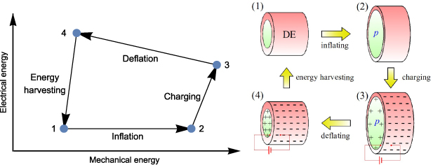
Figure 1. Energy harvesting cycle in DE tubes.
Download figure:
Standard image High-resolution imageAs a result of the inflating pressure, the tube dilates and gains mechanical energy. Next, the tube is electrically charged with a voltage V3 (see transition from point 2 to point 3). Owing to its dielectric properties, the DE tube experiences additional electrically-induced dilation. The magnitude of the charge on the inner and the outer surfaces of the tube is  .
.
Once the internal pressure is removed, the tube deflates and its radius decreases (see transition from point 3 to point 4). Practically, in stimulus-responsive materials the removal of the load is obtained through a change in environmental conditions. During this process, the total charge Q on the inner and the outer surfaces of the tube remains constant and the reduction in radius leads to a decrease in the capacitance C4. As a result, the voltage increases to the value  and energy can be harvested to complete the cycle (point 4 to point 1).
The overall electrical energy gained in this process can be written as
It is also convenient to define the energy-density per unit referential volume V0 (also termed the volumetric energy-density) of the undeformed DE tube as follows,
3. DE tubes—governing equations
Consider an infinite incompressible hyperelastic DE tube with a referential length L and inner and outer radii Ri
and Ro
, respectively. We introduce a polar coordinate system  and denote the material points in the reference configuration via
  ,
,  , and
, and  . The tube is subjected to an internal (inflation) pressure p and a potential difference
  along the radial direction. As a result, the tube dilates radially such that the inner and outer radii ri
and ro
, respectively, and the length l are achieved in the deformed configuration (see figure 2). The mapping of the material points can be written as
along the radial direction. As a result, the tube dilates radially such that the inner and outer radii ri
and ro
, respectively, and the length l are achieved in the deformed configuration (see figure 2). The mapping of the material points can be written as
and accordingly the deformation gradient is
Before proceeding, we recall the right Cauchy–Green strain tensor  and note that due to the incompressibility assumed for the DE tubes,
  .
.
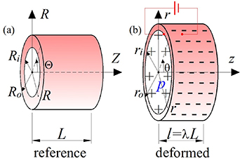
Figure 2. A schematic of the DE tube in the (a) reference and (b) inflated and charge states.
Download figure:
Standard image High-resolution imageFrom an electrical viewpoint, the electric field is determined from the electric potential via  , where the divergence operator is carried out with respect to the current (deformed) configuration of the system. The referential electric field is defined via
  [59].
[59].
The stress that develops in hyper-elastic DEs can be derived from a scalar strain energy-density function  . Following common practice, we assume that the strain energy-density function can be decomposed into two contributions,

where  denotes the mechanical behavior in the absence of an electric field, and
  accounts for the coupled electro-mechanical response [59–61]. Accordingly, the stress tensor is
where  and
and  are the mechanical and the coupled electro-mechanical stress components, respectively, and
  is a work-less pressure-like term that accounts for the incompressibility of the DE and is determined from the boundary conditions.
In this work, we consider isotropic DE tubes and consider a Yeoh-type energy-density function with n terms for the mechanical contribution,
where  is the first invariant and αi
are material constants (
is the first invariant and αi
are material constants ( ). Note that in the case of n = 1, the neo-Hookean form
  is recovered. It can also be shown that α1 is the initial shear modulus of the DE. The inclusion of higher order αi
-terms can be used to account for the strain-induced stiffening effect, commonly observed in polymers.
is recovered. It can also be shown that α1 is the initial shear modulus of the DE. The inclusion of higher order αi
-terms can be used to account for the strain-induced stiffening effect, commonly observed in polymers.
As for the coupled electro-mechanical energy, we consider the form proposed by Dorfmann and Ogden [59],

where εr and ε0 are the relative permittivity and the permittivity of vacuum, respectively.
The resulting Cauchy (true) stress tensor is computed by substituting equations (7) and (8) into equation (6),
From an electrical viewpoint, the applied potential difference V between the inner and the outer surfaces of the tube results in a radial electric field
where  is a unit vector along the radial direction. The capacitance is
and it is noted that the charge on the inner and outer surface is given by Q = VC.
To determine the equilibrium state, mechanical and electrical equilibrium as well as the boundary conditions must be satisfied. Due to the symmetry of the problem, the equilibrium equations along the θ and the z directions are automatically fulfilled. The only non-vanishing equation reads
where σrr
and σθθ
are the radial and the tangential stress components. The boundary conditions are given in terms of the radial and the longitudinal stress components. The tube is assumed to be traction free along its axis such that  . Along the radial direction, the stress at the inner and the outer radii is prescribed (i.e.
  and
and  , where p is the inflation pressure).
To solve the boundary value problem, we solve the equilibrium equation (equation (12)) to determine the work-less pressure-like term  . Next, we employ the three boundary conditions and the incompressibility constraint to determine the deformed radii ri
and ro
and the deformed length l. Accordingly, we can determine the configuration of the tube in the mechanically inflated state, the charged state, and the deflated state.
. Next, we employ the three boundary conditions and the incompressibility constraint to determine the deformed radii ri
and ro
and the deformed length l. Accordingly, we can determine the configuration of the tube in the mechanically inflated state, the charged state, and the deflated state.
4. Energy harvesting in DE tubes
In the following, we investigate the energy that can be harvested from a DE tube. To this end, we consider a tube with  ,
,  , and
, and  . The properties are taken as those of VHB 4910, which is an acrylic adhesive commonly employed as a DE [24, 32, 61–67]. Accordingly, we set the relative permittivity
  and the initial shear modulus
  . To show the influence of strain stiffening, we examine the neo-Hookean model and a Yeoh model with
  and
and  . All of the parameters are summarized in table 1. In addition, we define the dimensionless voltage
  .
.
Table 1. Geometry and material parameters used in the simulation.
| Parameter | Notation and value |
|---|---|
| Inner radius of DE tube |

|
| Outer radius of DE tube |

|
| Permittivity of VHB 4910 |

|
| Stiffness of VHB 4910 |
|
| Yeoh parameters for VHB 4910 |
 , , 
|
4.1. Electro-mechanical response of a DE tube
Based on the theoretical framework illustrated above, figure 3(a) plots the normalized external pressure  in the absence of voltage (
 ) as a function of the radial stretch
  . As expected, the neo-Hookean model predicts a softening of the DE tube with increasing the pressure while the Yeoh model accounts for the experimentally observed stiffening and lock-up effect.
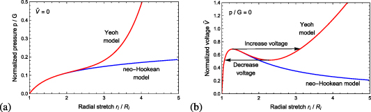
Figure 3. (a) Pressure p at V = 0 and (b) voltage V at p = 0 as a function of the inner radial stretch  .
.
Download figure:
Standard image High-resolution imageThe normalized voltage  as a function of the radial stretch
  in the absence of pressure (
 ) is depicted in figure 3(b). Note that the neo-Hookean model provides a response which reaches a peak voltage at
  , beyond which no solutions can be found. This non-physical behavior is a well-known drawback of the neo-Hookean model [61, 68]. The issue can be overcome by accounting for the strain-induced stiffening with the Yeoh model. This model predicts a snap-through of the tube at a critical voltage, followed by additional deformation and strain-induced stiffening.
In order to understand the harvesting mechanisms demonstrated in the next sections, it is worth emphasizing that the deformed configuration depends on the loading direction. Upon an increase in voltage, the DE tube snaps through at  such that the radial stretch increases from
  to
to  . Increasing the voltage results in further radial stretch. However, unloading from voltages that are above the critical value results in a reverse snap through from
  to
to  at
at  , thereby accessing different deformation states.
4.2. Active charging: mechanical inflation pressure
The active energy harvesting cycle, based on the application of a mechanical pressure (as described in section 2), is shown in figure 4. First, the referential DE tube is shown. As a result of an applied inflation pressure p, the DE tube inflates (state 2). State 3 describes the configuration of the tube after it has been charged with a charge  , where V3 and C3 are the voltage and the capacitance in the charged loaded tube, respectively. Due to electrostatic forces, a further deformation takes place in the tube from state 2 to 3. Lastly, the inflation pressure is removed (i.e. the tube deflates) while the charge Q is maintained (see state 4). This leads to a decrease in the capacitance
  and an increase in voltage
  .
.

Figure 4. Energy harvesting in DE tubes: active charging using pressure.
Download figure:
Standard image High-resolution imageIn the following, we investigate the energy which can be harvested from the DE tubes. To this end, we define and set the normalized inflation pressure  and control the charging voltage
  . It is emphasized that we assume that the material does not experience electrical breakdown, instabilities, or mechanical failure during the inflation and the charging process. In addition, it is worth noting that the inflation (which can be viewed as a prestretch of the material) allows for larger electrically induced deformations and thus reduces the likelihood of electrical breakdown [12, 69].
Figures 5(a) and (b) plot the normalized energy-density  and the difference in the capacitance
  as a function of the normalized voltage
  , respectively, for the neo-Hookean and the Yeoh materials with an inflation pressure
  . In the inflation stage, the pressure is not sufficient to observe the strain-induced stiffening of the DE and accordingly the deformed configurations of the neo-Hookean and the Yeoh materials are similar. As expected, charging the DE tube with higher voltages
  leads to an increase in the harvested energy e.
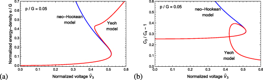
Figure 5. Normalized inflation pressure  : (a) The normalized energy-density
  and (b) the difference in the capacitance
  as a function of the normalized voltage
  for neo-Hookean and Yeoh materials.
Download figure:
Standard image High-resolution imageThe jump observed at  is the result of the electrically induced snap through effect (illustrated in figure 3(b)). To understand the simulated trends, figure 5(b) plots the difference in the capacitance. We find that for neo-Hookean materials, once a peak voltage is reached, no other solutions can be found. However, in the Yeoh material, the quantity
  initially increases, reaches a peak value, and then loops back towards 0. The 'loop' stems from the electrically-induced snap through and the differences between the loading-unloading response shown in figure 3(b). The value of
  reaches zero at high voltages due to the stiffening effect, in which the difference between the conformations in stages 3 and 4 is small. However, we emphasize that the harvested energy depends on
  , which is more dominant than the decrease in the capacitance ratio (see equation (1)).
The normalized energy-density  harvested for the higher normalized pressure
  is shown in figure 6(a). While the neo-Hookean model exhibits roughly the same trend as under lower pressures, the Yeoh model predicts a different response. Specifically, we find that the harvested energy does not monotonically increases with voltage. This behavior is explained as follows: the inflation pressure deforms the DE tube and leads to strain-induced stiffening. If the applied voltage in state 3 is in the snap through region of a DE tube that is electrically excited without mechanical loading, then the removal of the inflation pressure results in conformations which can only be accessed along the unloading path shown in figure 3(b). This effect must be considered when designing an energy harvesting DE tube.
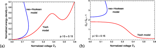
Figure 6. Normalized inflation pressure  : (a) The normalized energy-density
  and (b) the difference in the capacitance
  as a function of the normalized voltage
  for neo-Hookean and Yeoh materials.
Download figure:
Standard image High-resolution imageThe difference in capacitance  is shown in figure 6(b). As opposed to the case of
  , the quantity
  monotonically decreases with voltage according to the Yeoh model. This behavior stems from the application of a high inflation pressure, which deforms the tube into the strain-stiffening regime. This trend is also responsible for the drop
  at high voltages, since the deformed configurations 3 and 4 are similar.
It is important to note that given the applied shear modulus G, the above-illustrated simulations predict a harvesting of energy-densities in the range of ∼10–50 mJ cm–3 with VHB 4910. This is comparable to available experimental findings for VHB-based generators [29–32]. Specifically, with  an electrical energy-density of e ≈ 15 mJ cm–3 can be harvested at
  . The work of Jiang et al [32] harvested e ≈ 12 mJ cm–3 under an equivalent voltage in a cone DE generator with
  . At a voltage
  , a circular ring generator, as proposed by Wang et al [17], is capable of harvesting e ≈ 11 mJ cm–3, while our design predicts e ≈ 20 mJ cm–3. We point out that the differences stem from the charging mode—in our design the DE is charged radially while in the work of Wang et al [17] the electric field acts across the film.
4.3. Passive charging: swelling-induced inflation pressure
The main disadvantage of the above-described DE-based energy harvesting device is the need for a constant input of active mechanical energy (in the form of work of inflation pressure). Here, we propose an alternative method to harvest energy using a passive charging mechanism. Specifically, as opposed to mechanically applying a pressure, materials that deform in response to a change in environmental conditions such as temperature, hydration, and presence of liquids, can be employed to passively charge the energy harvesting device. The advantage of this method is that an environmental source triggers the deformation and generates mechanical energy, which is stored in the DE tube. In the following, we consider polymeric gels as the passive component. The gels swell in the presence of an appropriate solvent due to gel-solvent affinity, and in turn exert inflation pressure on the DE tube. In the following we describe the concept illustrated in section 2 with respect to a passive charging mechanism.
To demonstrate this concept, consider a long cylindrical neo-Hookean dry polymeric gel that is placed in a DE tube. A thin insulating, impermeable, and highly deformable membrane is placed between the gel and the DE to prevent direct contact of the charges with the solvent permeating the gel (see state 1 in figure 7). Next, the inner part of the tube is filled with solvent and the gel swells. As a result, the gel applies a pressure that inflates the tube, thereby storing mechanical energy (see state 2 in figure 7). In state 3 of figure 7, the tube is charged with a charge  . It is emphasized that in order to achieve a successful energy harvesting cycle, the contact between the gel, the insulating, impermeable, and highly deformable membrane, and the DE must be maintained. Practically, this leads to the requirement that the radial deformation of a freely swollen gel must be larger than the electrically induced radial stretch. Lastly, the solvent is drained out of the tube and the gel deswells (see state 4 in figure 7). As illustrated before for a mechanically applied inflation pressure, the charge is constant and therefore the capacitance
  and the voltage
  . Consequently, electrical energy can be harvested from the DE tube. From a practical viewpoint, it is emphasized that deswelling is a slow process, and therefore this mechanism is useful as a battery rather than a fast power supply source.
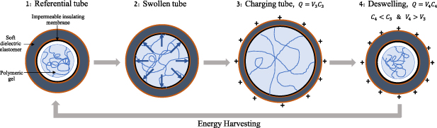
Figure 7. Energy harvesting in DE tubes: passive charging using swelling-induced forces.
Download figure:
Standard image High-resolution imageIn the following, we demonstrate the concept of passive charging. To this end, we summarize the governing equations and the boundary conditions of for the swelling of the constrained polymeric gels, as developed by Chester and Anand [70].
Consider a long cylindrical neo-Hookean dry polymeric gel with initial radius and length Ri
and Lg
, respectively. The material points are given in a polar coordinate system such that  ,
,  , and
, and  . The gel is placed in a dielectric tube, which is coated with an insulating impermeable membrane. The inner part is then filled with water and the gel swells. As a result, the gel applies a pressure that leads to the dilation of the tube.
In the deformed configuration, the radius and length of the gel are ri and lg , respectively. The mapping of the material points is given by

where λg and Ag are the radial and the longitudinal stretches. Accordingly, the deformation gradient is
where  is the volumetric deformation.
Following the framework of Chester and Anand [70], the stress that develops in the gel is
where Gg
is the shear modulus of the dry gel and  is a pressure-like term stemming from the solvent-polymer interactions and the mechanical interaction with the constraining tube. In addition, the chemical potential of the solvent molecules in the gel is given by
where k is the Boltzmann constant, T is the absolute temperature, µ0 is a reference chemical potential, χ is the dimensionless interaction parameter governing the gel-solvent affinity.
The boundary conditions are employed to determine the swelling-induced pressure. Specifically, the gel is traction free along the longitudinal direction such that  . Along the radial direction, the gel applies a radial stress that dilates the DE tube such that
  . Lastly, chemical equilibrium requires that
  .
.
To simulate the behavior of the system, we consider hydrogels and accordingly set the temperature and the volume of a water molecule  and
and  , respectively. We begin by studying the configuration of the system in state 2, which results from the application of the passive gel component due to swelling. Figures 8(a) and (b) plot the stretch
  of the gel tube as a function of the stiffness ratio
  for selected values of χ in systems with neo-Hookean and Yeoh DE tubes, respectively. We find that extremely soft gels (i.e.
  ) experience little swelling. This is due to the stiffness of the DE tube, which constrains the gels from dilating and expanding [71]. Stiffer gels with a shear modulus that is comparable to that of the DE exert larger swelling-induced stress on the tube and therefore experience significant radial swelling, resulting in higher mechanical energy of the DE tube. As can be seen, the radial stretch varies non-monotonically with the stiffness ratio, resulting in an optimum value
  in both neo-Hookean and Yeoh tubes that leads to maximum radial stretch. This ratio is important since it governs the capacitance of the DE tube in state 3. In addition, note that lower interaction parameters, corresponding to gels with a higher polymer-solvent affinity, result in increased swelling, as expected [16, 72, 73].
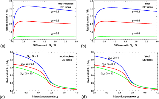
Figure 8. Passive mechanical loading using hydrogels: The radial stretch of the gel  as a function of (a), (b) the stiffness ratio
  and (c), (d) the interaction parameter χ for neo-Hookean and Yeoh DE tubes.
Download figure:
Standard image High-resolution imageFigures 8(c) and (d) plot the stretch  of the gel tube as a function of the interaction parameter χ for three selected values of
  in systems with neo-Hookean and Yeoh DE tubes, respectively. The interaction parameter governs the gel-solvent affinity, and therefore lower χ values result in a larger degree of swelling. The degree of swelling decays as the interaction parameter χ increases. These plots highlight the non-monotonous trends of the degree of swelling with the ratio
  . Specifically, gels with a stiffness that is comparable to that of the DE tube experience significant swelling and apply interfacial pressures which are sufficient to significantly deform the tubes. In the case of
  , the gels cannot exert sufficient interfacial pressure to stretch the DE tube. Therefore, the behavior is governed by the gel-fluid affinity—lower values of χ lead to larger solvent uptake and radial stretch. Stiff gels, as shown via
  , are characterized by a high chain-density which mechanically hinders swelling. Therefore, the radial stretch obtained from such gels is smaller than with
  .
.
To investigate the energy harvesting capabilities of the gel-DE system, we choose the shear moduli ratio  and the dimensionless gel-fluid interaction parameter χ = 0.2, a value that corresponds to a high gel-fluid affinity. Figures 9(a) and (b) plot the normalized energy-density
  and the difference in the capacitance
  as a function of the normalized voltage
  for neo-Hookean and Yeoh materials. The observed trends suggest that the inflation pressure applied by the gel, resulting in state 2, deforms the tube to the stiffening regime, as explained in relation to the above discussed case characterized by
  in the active charging (see figures 6(a) and (b). In addition, the electrical energy-density that can be harvested using passive charging is comparable to that obtainable with active charging under the examined properties. Specifically, under the voltages
  and
and  , the energy-densities e ≈ 14 mJ cm–3 and e ≈ 18 mJ cm–3 can be harvested. This is comparable to available experimental results. However, it is again emphasized that due to the diffusion mechanism that governs swelling, the charging is a slow process.

Figure 9. Energy harvesting using passive charging: (a) The normalized energy-density  and (b) the difference in the capacitance
  as a function of the normalized voltage
  for neo-Hookean and Yeoh materials.
Download figure:
Standard image High-resolution image
5. Conclusions
In this work, we explore the energy which can be harvested from DE tubes. To this end, we employ the neo-Hookean and the Yeoh models for the mechanical response of the DEs along with a well-known energy-density function that accounts for the electro-mechanical coupling. We begin by demonstrating the purely mechanical and the electro-mechanical response of DE tubes. As expected, the Yeoh model, which captures the strain-stiffening of elastomers, leads to the snap-through behavior under electric excitation.
Next, we investigate energy harvesting in two contexts: active charging and passive charging. In the former, the tube is inflated though an applied internal pressure. In the latter, a gel rod is placed in the tube and allowed to swell, resulting in inflation of the DE tube. Next, a voltage is applied across the tube, resulting in electro-mechanically induced deformations. Once the internal pressure or the gel are removed, energy can be harvested. Our simulations show that the energy-density which can be gained through an inflation-deflation cycle under active or passive charging is ∼10–50 mJ cm–3, which is the same order of magnitude obtained in previous works with VHB DEs.
It is important to note that from a practical viewpoint, active charging can be used to quickly charge and harvest electrical energy from the device. The resulting electrical power is proportional to the rate of pressure increase/decrease. Accordingly, this design is useful in systems that require high electric power. Passive charging through gels is slow and governed by the diffusion of solvent molecules into the network. While this may be a drawback, the advantage of such a system is that no mechanical energy is required in order to charge (the radial deformation of the DE tube is through the autonomous swelling of the gel). This type of design can be used as an efficient energy source (or battery).
In conclusion, this work investigates energy harvesting in DE tubes and proposes a method to mechanically charge the system through unconventional environmental conditions using stimulus-responsive polymers. These systems can be used as a battery source that can be charged through ambient conditions, thereby providing a different approach for energy storage and supply in remote systems.
Data availability statement
All data that support the findings of this study are included within the article.