
Abstract
A transduction modality based on inter-ferroelectric (FE) transitions in domain engineered single crystals, poised near an instability via mechanical clamping is reviewed. The phase transition is associated with strain levels that are much higher than what could be achieved using the linear piezoelectric mode. They are also accessible at significantly lower drive fields compared to the free state. The large FE–FE polarization change accompanying the phase switching has been utilized to demonstrate the vast electromechanical and thermal energy conversion capabilities of this sensing modality. The harvested mechanical energy density per cycle is nearly two orders of magnitude larger than that of linear piezoelectric bimorphs operating in a resonance-mode. Additionally, being a non-resonant modality, the problems associated with matching the harvester's frequency to that of the structure (for maximum output) are obviated. Magnetoelectric energy harvesters and sensors have demonstrated similarly large coefficients. Compact broadband sound projectors fabricated using this modality have delivered 10–15 dB more source level over two and half octaves compared to the linear piezoelectric mode counterpart. Ongoing research in utilizing this modality in electro-optic modulation is discussed. Advances that have occurred over the last decade in fundamental understanding of this transduction modality and device physics are presented. It is our intent that this up-to-date review will stimulate interest in the applied physics community to further explore the benefits of this transduction modality. This review also summarizes fundamental knowledge gained of relevant issues. The focus of this review is on single crystals and thus the recent work on lead free ceramics is not addressed.
Export citation and abstract BibTeX RIS

Original content from this work may be used under the terms of the Creative Commons Attribution 4.0 license. Any further distribution of this work must maintain attribution to the author(s) and the title of the work, journal citation and DOI.
1. Introduction to high coupling single crystals
The development of high electromechanical coupling, domain engineered single crystals was motivated by the demanding requirements for compact, lightweight, broadband, high source level, underwater sound projectors. These projectors are typically operated at low frequencies (kHz), with a duty cycle (up to 100%). They are driven by a large field ∼0.4 MV m−1 (rms), and maintained under a compressive stress up to 60 MPa. There was also the need for medical ultrasound arrays capable of volumetric (three dimensional), real time imaging, with enhanced axial resolution, and contrast. These arrays operate in the high frequency (GHz) regime. Transducers fabricated using conventional lead zirconate titanate (PZT) and lead magnesium niobate (PMNT) piezoceramics are incapable of meeting these requirements. To overcome the shortcomings of traditional piezoceramics, a search for a new class of piezoelectric materials with the potential for high electromechanical coupling, large piezoelectric coefficient, and small Young's modulus was initiated in the mid 1990s. Large coupling factor and piezoelectric coefficients would provide the broadband, axial resolution, and high source level capabilities. A large compliance (small Young's modulus) would enable sound projector size reduction, or alternatively, accessing lower frequency keeping size the same. Additionally, to minimize heat generation and temperature rise during large drive, and full duty cycles, high electrical and mechanical quality factors would be required. The piezoelectric material also needed to exhibit a sufficiently large coercive field to avoid de-poling during hard drive operation.
A longitudinal piezoelectric d33 of 1500 pC N−1 and electromechanical coupling k33∼ 0.92, short circuit Young's modulus YE ∼ 15 GPa were first reported in early 1980s for a [001] oriented and poled multi-domain lead zinc niobate-lead titanate (PZNT) single crystal with a nominal composition 0.91Pb (Zn1/3Nb2/3)O3-0.09PbTiO3 [1, 2]. These investigations were performed by a resonance method under a relatively low drive field, far below that required to saturate the electrically-induced strain. The high field response of [001] oriented 0.92Pb (Zn1/3Nb2/3)O3-0.08PbTiO3 and lead magnesium niobate-lead titanate (PMNT) crystals have been reported [3, 4]. Electrically induced strain in excess of 1.1% (an order of magnitude larger than conventional hard lead zirconate titanate PZT8) was reported at field levels of ∼4 MV m−1. Several phases can be induced in these crystals including ferroelectric (FE) rhombohedral FR, FE orthorhombic FO, and FE tetragonal FT. The origin of the high electromechanical behavior has been attributed to an electrically-induced FR − FT phase transformation.
1.1. Polarization rotation and low symmetry FE phases
First principles computations by Fu and Cohen [5] indicated that the large strain values observed in FE rhombohedral PZNT crystals under a [001] electric field can be attributed to polarization rotation from the rhombohedral [111] to the tetragonal [001] polar axis. Amin and Cross [6] calculated the strain associated with FR − FO, FR − FT, and FT − FO transitions using Devonshire theory. The calculated strain associated with the FR − FT transition was 1%, in a good agreement with the experimental value of ∼1.1%. The presence of FE monoclinic (FM) and FE orthorhombic (FO) states between the FR and FT phases in the PMNT and PZNT systems have been confirmed by diffraction, dielectric, and optical measurements [7–11].
Vanderbilt and Cohen [12] extended the Devonshire theory of perovskite FEs to account for the observed monoclinic Fm phase. Using spherical coordinates instead of the customary Cartesian coordinates, the energy function (Gibbs free energy) was represented by an analytic function defined on the surface of a sphere and truncated at the 8th power of the polarization vector (order parameter) normalized to unity. The parameter space was thus a unit sphere spanned by the polar and azimuth angles α and β respectively, where 0 < α < π and 0 < β < 2π. The FE phases were obtained by numerically searching for constrained minima of the energy function as a function of orientation. The constraints were taken such that the order parameter must lie along a symmetry axis, i.e. [001, 111], or [011] for the FE tetragonal, rhombohedral, or orthorhombic phases respectively, or in a symmetry plane (mirror) for monoclinic FE phases. Three monoclinic phases are admissible MA, MB, and MC as illustrated in figure 1.

Figure 1. Polarization directions for the possible ferroelectric symmetries, see text for details [12].
Download figure:
Standard image High-resolution imageA two-dimensional representation of the FE phase diagram in terms of the linearly independent parameters α and ® was obtained by mapping the unit sphere onto a two-dimensional plane. This model can only describe inter FE transitions, and not transitions to the high temperatures paraelectric (PE) state. In this model, temperature, composition, elastic, and electric variables are not explicit, but it was the first to provide first principles calculations of the phase behavior observed in these crystals.
1.2. Single crystal growth techniques and compositions
Significant progress has occurred over the last two and half decades in growth techniques, crystal quality and homogeneity, boule size, and commercial availability. The main focus has been in: (1) binary relaxor-FE with the general formula: (1 − x)Pb(B1/3Nb2/3)O3-(x)PbTiO3
, where B can either be Mg or Zn, with x∼ 0.06–0.08 for Zn compositions, and x∼ 0.28–0.32 Mg compositions, (2) ternary compositions in the system lead indium niobate-lead magnesium niobate-lead titanate (PINMT) with the general formula xPb (In1/2Nb1/2)O3 -(1 − x − y)Pb (Mg1/3Nb2/3) O3-(y) PbTiO3
, with y∼ 0.24–0.30 and pseudo-binary lead magnesium niobate (1 − x)Pb(Mg1/3Nb2/3)O3
-lead zirconate titanate (x)Pb(Zr,Ti)O3
(PMNZT). The single crystal growth technique depends on the relaxor-FE system. Modified and continuous feed Bridgeman (CFB) are used to grow binary PMNT and ternary PINMT single crystals [13, 14], the flux method is used for PZNT [15], and the solid state conversion growth method for PMNZT [16]. The relaxor-FE single crystal compositions of interest in acoustic transduction are those with high electromechanical coupling coefficients. For instance, the electromechanical coupling factor  for length extensional vibration modes is
  , where, d33 is the piezoelectric coefficient,
  the short circuit Young's modulus, and
  the free (unclamped) dielectric constant, and
 the free space permittivity (8.854 × 10⁻¹² F m−1).
Compositions of interest in acoustic transduction devices (both active and passive) are located near a FE rhombohedral FR–FE tetragonal FT degeneracy, the so called morphotropic phase boundary (MPB) where the electromechanical properties are maxima. The relaxor-FE single crystals reported in this review are the result of multiyear collaborative research projects with the crystal growers under ONR and DARPA contracts [13–16].
1.3. The morphotropic phase boundary (MPB)
The MPB is found in several perovskite FE systems with the general formula A(BI 1−xBII x)O3 . Besides, PZNT, PMNT, and PINMT, the lead zirconate titanate (PZT) solid solution system is perhaps the best-known and most extensively investigated. It comprises most of the technologically important piezoelectric compositions used in the electronics industry today. These compositions have a Zr, Ti ratio ∼1 near the MPB. In the composition-temperature phase diagram, a MPB may be considered as the temperature trajectory of the free energy degeneracy of two FE phases with distinct symmetry subgroups of the higher temperature PE symmetry group. In the present case, these are a FE tetragonal phase FT (4mm symmetry) with the polarization vector along the four-fold symmetry axis, and a FE rhombohedral phase FR (3m symmetry), with the polarization vector along the three-fold symmetry axis. Both 4mm and 3m are polar subgroups of the centrosymmetric, higher temperature PE phase m3m. A FE orthorhombic phase FO (2mm symmetry) with the polarization vector along the two-fold symmetry axis is also allowed.
A computed phase diagram for perovskite FEs with the general formula A(BI 1−xBII x)O3 , with 1 ⩾ x⩾ 0, a tetragonal (4mm), and a rhombohedral (3m) FE as end members is depicted in figure 2(a). The computations were carried using a modified 6th order Devonshire free energy density function (elastic Gibbs) under free elastic and electric boundaries, and a linear TC versus composition across the composition field [17]. Numerical analysis of the full three-dimensional elastic Gibbs free energy density, suggested that a rhombohedral–tetragonal degeneracy (morphotropy) can be generated over a wide temperature range without any interleaving orthorhombic region for the PZT system, figure 2(b). However, the orthorhombic FE phase is always close to but metastable with respect to the rhombohedral and tetragonal phases [17]. A superposition of the experimental and phenomenological phase diagrams is illustrated in figure 2(c). Heitmann and Rosetti [18, 19] have used the concept of vanishing anisotropy upon approaching the MPB in conjunction with a 6th order Devonshire series to mimic the MPB. Recently, Lv et al [20] developed a 10th order Landau–Devonshire energy function with a maximum polarization constraint to describe the dielectric, piezoelectric, and FE properties of PINMT relaxor FEs.

Figure 2. (a) A(BI 1−xBII x )O3 phase diagram as computed from free energy density minima and a linear TC vs composition, showing a near vertical MPB between the tetragonal FT and rhombohedral FR ferroelectric phases, (b) the elastic Gibbs free energy for the tetragonal, rhombohedral, and orthorhombic phases plotted versus composition across the single cell region of the PZT phase diagram at three temperatures, and (c) superposition of the experimental (points) and phenomenological (line) phase diagrams [17].
Download figure:
Standard image High-resolution imageThe Pb(Zn1/3Nb2/3)O3-PbTiO3 and Pb(Mgn1/3Nb2/3)O3-PbTiO3 phase diagrams near the MPB are illustrated in figures 3(a) and (b) respectively. Similar to the PZT system, the MPB separates tetragonal (4mm) and rhombohedral (3m) FE regions. The makeup of the MPB in the binary (1 − x)Pb(B1/3Nb2/3) O3-(x)PbTiO3 system has been the subject of several structural investigations using high-brilliance high-resolution synchrotron radiation. It has been found that morphotropic (1 − x)Pb(Mg1/3Nb2/3) O3-(x)PbTiO3 compositions with 0.31 ⩽ x⩽ 0.37 are complex mixed states (figure 3(b)) of rhombohedral, tetragonal, monoclinic and orthorhombic phases [21]. As pointed out by the authors, diffraction patterns of relaxor-FE systems such as (1–x)Pb(B1/3Nb2/3)O3-(x)PbTiO3 are extremely difficult to analyze, especially for compositions close to a MPB. Two major factors contribute to this complexity: (1) compositional inhomogeneity due to the concentration gradient typical of crystal growth from melt of incongruently melting compositions, and (2) the broad diffraction maxima characteristic of disordered relaxor-FE systems. This complicates peak deconvolution of overlapped or partially overlapped reflections in the reciprocal (Fourier) space. Overlapping reflections in Fourier space are common in pseudo symmetric structures, such as FT, FR, FO, and FM of the present systems.

Figure 3. (a) Pb (Zn1/3Nb2/3 )O3-PbTiO3 adapted from [2, 22] and (b) schematic Pb (Mgn1/3Nb2/3 )O3-PbTiO3 phase diagrams near the morphotropic phase boundary (MPB).
Download figure:
Standard image High-resolution imageSignificant advances in compositional homogeneity have been achieved by JFE corporation [14] recent development of CFB techniques for growing relaxor-FE PINMT single crystals. This has resolved, or at least minimized the uncertainty in determination of phase symmetry from diffraction data.
Historically, similar arguments were presented in the early 70s regarding the MPB composition of PZT (figure 2(c)). Isupov [23] reported the possible existence of an extended region of mixed tetragonal and rhombohedral FE states for xPbZrO3-(1 − x)PbTiO3, Gur-Ari and Benguigui [24] suggested a coexistence region of the tetragonal and rhombohedral states for 0.49 ⩽ x⩽ 0.62. On the other hand, Kagekawa et al [25] noted that morphotropic xPbZrO3-(1 − x)PbTiO3 compositions prepared by a combination of wet-dry technique exhibited no coexistence of the tetragonal and rhombohedral states. Additionally, for compositions prepared by a dry technique, the observed (200) x-ray diffraction line broadening was attributed to compositional fluctuations rather than lattice strain.
1.4. The perovskite A2+B4+O2− 3 crystal structure
Above the Curie temperature TC, the prototypic high temperature, PE structure PC from which the FE states are derived is cubic with space group Pm3m and a lattice constant a ∼ 0.4 nm (figure 4). The A-site can be occupied by a divalent cation such as Pb, Ba, Sr, Zr and the B-site by a tetravalent cation such as Zn, Nb, Mg, Nb, or Ti. There are two equivalent representations of the perovskite structure: (1) corner shared BO6 octahedra, with the A2+ placed at ½, ½, ½ along the body diagonal as in figure 4(a), and (2) the A2+ is placed at the corners of the cubic unit cell (figure 4(b)). Below TC, the B4+ cation is shifted along ±<100>c, or ±<111>c symmetry axes relative to the O2− 6 octahedra framework, developing a FE tetragonal P4mm phase with polarization vector along the four-fold symmetry axis, or a FE rhombohedral R3m phase with polarization vector along the three-fold axis. Other allowed FE phases are orthorhombic (Bmm2) with polarization vector along the two-fold symmetry axis, and monoclinic (m) with polarization vector in the mirror plane. Structural details for isomorphic barium titanate can be found in the classic textbook Ferroelectricity by Jona and Shirane [26].
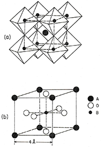
Figure 4. The cubic perovskite ABO3 structure above TC.
Download figure:
Standard image High-resolution image1.5. Domain engineering and macro-symmetry
According to Shuvalov [27], knowing the spontaneous polarization symmetry group (∞ mm) and varying the direction of the spontaneous polarization with respect to the symmetry elements of Gp (the PE state symmetry group), one can find all possible FE groups GF1, GF2, resulting from GP by applying Curie symmetry principle. The Curie symmetry principle may be stated as follows: The symmetry elements of the FE state group GF consist of all the symmetry elements common to GP and ∞ mm i.e., GF = GP ∩∞ mm such that GF ⊂ GP.
The number of orientation (domain) states associated with a phase transformation from a prototypic PE cubic PC state, with a point group symmetry GP (m3m) to a FE rhombohedral FR point group (3m) or FE tetragonal FT point group (4mm) GF, is given by the index N of GF in GP. According to Aizu [28], there are six fully FE partially ferroelastic domain states present for the tetragonal (4mm) symmetry, eight for the rhombohedral (3m), twelve for the orthorhombic (2mm), and twenty-four for the monoclinic (m). Starting with a FE rhombohedral FR single crystal, the engineered domains can be formed by applying a poling field (∼5–10 kV cm−1) along the [001]C, which will assemble the four FR macro domain pattern with polarization vectors of each domain along one of the possible four [111]C, [ ]C, [
]C, [ ]C, [
]C, [ ]C, directions. The resulting macro-symmetry is 4mm and is often referred to as 4R due to the presence of only four of the rhombohedral variants. Similarly, a poling field along [011]C will generate a macro-domain arrangement of <111> polarization vectors to form mm2 macro-symmetry that is often referred to as 2R. Domain engineered single crystal modes that were investigated for potential applications in sound projectors, and other transduction devices are discussed next. Unless otherwise stated, a right-handed Cartesian coordinate system is used as a reference frame. In figure 5, the crystallographic axes are embedded in the reference frame, and the applied uniaxial compression, drive field, and the induced strain directions are shown for the following domain engineered modes: (a) macro-symmetry 4mm, 33- length extensional (4R 33 mode), (b) macro-symmetry 2mm, 32- transverse length extensional (2R 32 mode), (c) macro-symmetry 2mm, 31-transverse length extensional (2R 31 mode), and (d) macro-symmetry 2mm, 33-mode length extensional (2R 33 mode).

Figure 5. Crystal orientation, uniaxial stress, and drive fields are shown for the following modes (a) macro-symmetry 4mm, 33-length extensional, (b) macro-symmetry 2mm, 32-transverse length extensional, (c) macro-symmetry 2mm, 31-transverse length extensional, and (d) macro-symmetry 2mm, 33-length extensional.
Download figure:
Standard image High-resolution image1.6. Ferroelastoelectric domains
It was suggested [29] that the twin structure of domain engineered crystals with macro-symmetry 2mm, afforded by two domain states [111]C and [ ]C are of the ferroelastoelectric type. A crystal is said to be ferroelastoelectric if it contains two or more domain states that can be switched by the simultaneous application of mechanical stress and electric field. Quartz is perhaps the best known ferroelastoelectric material. It belongs to the ferroic species 622F32, where 622 is the symmetry group of the high temperature phase, and 32 is that of the lower temperature. The letter F indicates ferroic behavior. Primary effects such as ferroelectricity, ferroelasticity, and ferromagnetism are forbidden in this symmetry species. Secondary ferroic effects such as ferroelastoelectricity are allowed and have been experimentally demonstrated [30]. The Dauphine or electric twin states are related by 180° rotation about the optic axis (three-fold symmetry axis). Hence, the positive a-axis in one twin component becomes the negative a-axis in the other twin component. Consequently, the piezoelectric coefficients d111 and d122 (=d111) reverse signs in Dauphine twins. The driving potential for ferroelastoelectric state shifts can be synthesized in terms of the difference in one or more piezoelectric components Δdijk
and the applied electric Ei
and mechanical σjk
fields. Cao and Amin [31] developed a theoretical model that enumerated the symmetry allowed ferroelastloelectric modes in crystals with macro-symmetry mm2. The driving potential inclusive of all the allowed modes for [111]C and [
]C are of the ferroelastoelectric type. A crystal is said to be ferroelastoelectric if it contains two or more domain states that can be switched by the simultaneous application of mechanical stress and electric field. Quartz is perhaps the best known ferroelastoelectric material. It belongs to the ferroic species 622F32, where 622 is the symmetry group of the high temperature phase, and 32 is that of the lower temperature. The letter F indicates ferroic behavior. Primary effects such as ferroelectricity, ferroelasticity, and ferromagnetism are forbidden in this symmetry species. Secondary ferroic effects such as ferroelastoelectricity are allowed and have been experimentally demonstrated [30]. The Dauphine or electric twin states are related by 180° rotation about the optic axis (three-fold symmetry axis). Hence, the positive a-axis in one twin component becomes the negative a-axis in the other twin component. Consequently, the piezoelectric coefficients d111 and d122 (=d111) reverse signs in Dauphine twins. The driving potential for ferroelastoelectric state shifts can be synthesized in terms of the difference in one or more piezoelectric components Δdijk
and the applied electric Ei
and mechanical σjk
fields. Cao and Amin [31] developed a theoretical model that enumerated the symmetry allowed ferroelastloelectric modes in crystals with macro-symmetry mm2. The driving potential inclusive of all the allowed modes for [111]C and [ ]C state shifts under the combined application of mechanical stress and electric field was also developed. We list below the driving potential ΔG for one of the allowed modes, i.e. for a colinearly applied uniaxial compression σ2, and electric field E2 along the X2 axis for 2mm domain engineered crystal (figure 5(b)). Experimental verification of this mode is presently underway,
where,
and dij are the piezoelectric tensor coefficients for the 3m symmetry group [32].
2. Inter-FE transitions: stability of domain engineered single crystals, under electric field, mechanical stress, and temperature
In this section we will discuss the experimentally observed effects of electric field, mechanical stress, and their orientation relative to the crystallographic axes, on the stability of domain engineered single crystals at several temperatures. The crystals were fabricated from morphotropic compositions, close to the MPB (section 1.2) on the rhombohedral side of the phase diagram. The desired macro-symmetry was achieved by applying a poling field along a symmetry axis (section 1.5) For instance, a macro-symmetry 4mm was obtained by applying a poling field along the four-fold symmetry axis, the pseudo-cubic [001]C to produce a 4R domain ensemble (figure 5(a)). Similarly, a 2mm macro-symmetry was generated by applying a field along the two-fold symmetry axis to form 2R domain ensemble (figures 5(b)–(d)). The 4mm, and 2mm domain engineered crystals with geometrical dimensions suitable to excite the 33-, 32-, and the 31-vibration modes are discussed.
2.1. Macro-symmetry 4mm: (4R 33 mode) and model prediction
The effect of an electric field applied along the X3 direction (the domain engineering four-fold symmetry axis) of PZNT (4.5%PT) single crystals with macro-symmetry 4mm (figure 5(a)), was investigated by Park and Shrout [3, 4] and illustrated in figure 6(a). The mechanical compression–decompression response along the X3 direction of PZNT (6%PT) single crystals is shown for several temperatures in figure 6(b) [22].

Figure 6. (a) Strain vs. field response of domain engineered PZNT (4.5% PT) single crystal with macro-symmetry 4mm, a strain level ∼1.1% is associated with a ferroelectric rhombohedral FR–ferroelectric tetragonal FT transition [3, 4]. (b) The compression–decompression response at several temperatures of domain engineered PZNT (6% PT) single crystals with the same macro-symmetry, a strain level of ∼0.45% near 5 MPa compression at 20 °C is attributed to a ferroelectric rhombohedral FR–ferroelectric orthorhombic FO transition [22].
Download figure:
Standard image High-resolution imageThe PZNT (6%PT) crystals have a high electromechanical coupling k33 ∼ 0.93, a piezoelectric coefficient d33 ∼ 2300 pC N−1, and short circuit Young's modulus ∼9 GPa as deduced from small signal resonance—antiresonance experiments. The relationships between the strain magnitudes associated with inter-FE transitions that are polar subgroups of the symmetry group m3m, namely, the tetragonal 4mm, the rhombohedral 3m, and the orthorhombic 2mm were developed by Amin and Cross [6]. Assuming polarization continuity in the pseudo-cubic tetragonal (T), the rhombohedral (R), and the orthorhombic (O) states, i.e. P2 T = 2 P2 O = 3P2 R, the magnitude of the X3 strain components are:


where Qij are the electrostriction coefficients and PR, PO, PR the polarization components along pseudo-cubic axes. Substituting Q11 = 0.054 m4 C−2, Q12 = −0.027 m4 C−2, and PR = 0.25 C m−2 in the above expressions we get for SR–T a value of 1% which is in close agreement to the experimental values of 1.1% in figure 6(a). A possible transition path under field may occur via an intermediate monoclinic state MA between the initial FR (macro-polarized) and the final FT (mono-polarized) states shown in figure 1. For SR–O the calculated value of 0.50%, is close to the observed 0.45% (figure 6(b)). The forced orthorhombic state on compression will not be macro-polarized as the four equivalent <111> polarization vectors will rotate in the (111) mirror planes and eventually fold out into 90° and 180° domain states The reversible FO − FR transition upon decompression could be due to compensation charges on charged domain walls which pull the polarization vectors back to the FR state. A possible transition path under compression may occur via an intermediate monoclinic state MB between the initial FR and the final FO states as shown in figure 1. Further evidence will be discussed in the section dealing with x-ray and synchrotron studies. There is no strain difference associated with the FO − FT transition. In other words, for an observable difference in the strain, the condition 2 P2 O > P2 T must be fulfilled. There is no valid reason to accept this condition. At higher temperatures, the spontaneous strain and the critical stress magnitudes are decreased (figure 6(b)), as a consequence of decreased polarization levels and increased elastic softening respectively. Applied electric fields along the domain engineering axis, i.e. the four-fold symmetry axis, will stabilize the four rhombohedral (4R) domain ensemble to higher compression levels [22] as shown in figure 7.

Figure 7. The effect of an applied electric field parallel to the domain engineering axis, i.e. the four-fold symmetry axis of domain engineered PZNT (6% PT) single crystals (4R 33 mode). Note: the electric field of 0.8 MV m−1 stabilized the four rhombohedral (4R) domain ensemble over an extended compression level [22].
Download figure:
Standard image High-resolution image2.2. Macro-symmetry 2mm: 32-, 31-, and 33- modes (2R 32, 31, and 33 modes)
The transverse length extensional 32-mode geometry (2R 32 mode), with domain engineered macro symmetry 2mm (figure 5(b)) provides greater design flexibility in terms of mechanical loading (pre-stress) and electrical interconnect compared to the 33-mode tonpilz sound projector's design (4R 33 mode). Figure 8(a) illustrates the isothermal (20 °C) uniaxial compression–decompression response along the X2 direction of domain engineered PZNT (6% PT) single crystal. The crystal has a high electromechanical coupling k32 ∼ 0.91, a piezoelectric coefficient d32 ∼ 2100 pC N−1, and short circuit elastic compliance sE 22 ∼ 148 pm2 N−1 as deduced from small signal resonance–antiresonance experiments. The response of both the unbiased and dc biased crystal is shown in figure 8(a). The dc bias is applied along the X3 axis, which is same as the [011] domain engineering (poling) axis. The 50 °C response is shown in figure 8(b) [29].

Figure 8. (a) Uniaxial compression–decompression 2R 32 mode strain response without dc bias field (black trace) and with 0.4 MV m−1 bias (blue trace) at 20 °C of domain engineered PZNT (6% PT) single crystal. Note the large strain (∼0.45%) associated with the FR − FO transition. Intermediate bias responses were omitted for clarity. The inset depicts a plot of the intermediate stress vs. field levels responsible for the FR − FO transition. (b) The response at 50 °C, an electric field of 0.35 MV m−1 along the domain engineering two-fold symmetry axis is sufficient to stabilize the FO state [29].
Download figure:
Standard image High-resolution imageIn figure 8(a), starting with the initial FR state at zero field (black trace), the strain increases with compression nearly linearly up to ∼12 MPa, then it is followed by a large increase ∼.45% associated with the FR − Fo transition. A similar qualitative response is followed under a dc bias of 0.4 MV m−1 (blue trace), except the transition occurs at a lower stress level ∼6 MPa. This is because both the applied field along the [011], and the compressive stress along the [100] will induce a FR − Fo transition caused by polarization vectors [111] and [ ]C rotating in the mirror plane towards the [011] direction to form a mono-polarized FO state. The inset depicts a plot of the intermediate stress vs. field levels responsible for FR − FO transition. Figure 8(b) depicts the response at 50 °C. Following the work of McLaughlin et al on 32-mode measurements of PMNT (32%PT) under stress and field [33], it is possible to construct a three-dimensional representation of the crystal stability in the stress-field-temperature parameter space as shown in figure 9. States below a phase boundary surface (marked with dashed outline) are stable FR, those above are stable FO. States which lie on the surface are poised near a FR − FO transition.
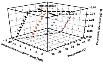
Figure 9. Three-dimensional representation of 32-mode stability of domain engineered PZNT (6% PT) single crystal in the stress-temperature field parameter space. Note the phase boundary surface (dashed outline) separating stable FR and FO states (see text for details) [29].
Download figure:
Standard image High-resolution imageThis representation is useful for establishing design rules and drive parameters for sound projectors operating within the high coupling linear piezoelectric regime. Additional surface below that shown in figure 9 may be constructed to represent the crystal response under decompression, and the hysteretic effect associated with the reversible FO − FR transition. This is discussed further in section 4. There are a number of ways to cause the polarization vectors along [111] and [ ]C of the 2R domain engineered crystal to rotate: (1) a compressive stress only along X2 will induce a FR (macro-polarized)–FO (mono-polarized) transition at ∼12 MPa in this composition, upon decompression, the FR state is restored, because the FO mono-polarized state is unstable under free electric and elastic boundaries; (2) an electric field only (∼0.75 m−1) along the X3 (the two-fold symmetry axis,) or (3) a combination of stress and field, i.e. any point on the stability surface (figure 9). A possible transition path under compression may occur via an intermediate monoclinic state MB between the initial FR and the final FO states. Experimental evidence is presented in section 3 dealing with x-ray and synchrotron scattering experiments under stress and field.
There are differences in stress and field effects on the stability of the 2R domain ensemble of the 2mm macro-symmetry (2R 32 mode), compared to the 4mm (4R 33-mode). In the former both compressive stress and electric field will destabilize the 2R variants, while in the latter, compressive stress along the [001] direction has a destabilizing effect on the four FR variants and drives them toward a FO variant, whereas, applied electric fields along the [001] direction will stabilize the 4R ensemble to higher compression levels and at high enough electric field will destabilize them toward a single FT variant.
The 31-mode stability under the influence of compressive stress and applied electric field of domain engineered 2R ensemble with 2mm macro-symmetry (2R 31 mode) (figure 5(c)) was investigated for a morphotropic PZNT composition with 5.5% PT content [34]. The room temperature uniaxial compression–decompression response at 0.0 and 1.5 MV m−1 is illustrated in figure 10(a). The stability of the FR state up to 90 MPa compression under zero field is believed to be the highest observed compression level among any crystal investigated. Also shown in figure 10(a) is the stress level (∼30 MPa) required to induce a stable, high coupling FR state over high compression levels, for a 1.5 Mv m−1 dc biased FO initial state. Therefore, both conditions for large drive, and high compression are satisfied. These are desired design features for sound projectors operating at high drive fields. The strain versus field along the [011] is depicted in figure 10(b). The strain associated with FR − FO transition is given by, SR–O [011] = [0.25 (Q11− Q12) + Q44)] PR 2 = 2010 micro strain, in a good agreement with observed 2200. The phase transition from FR to FO under field proceeds by rotation of the 2R polarization vectors in the mirror symmetry plane to a final stable (under field) mono-domain FE orthorhombic FO state, having the polarization vector along the [011] symmetry axis.

Figure 10. (a) Room temperature uniaxial compression–decompression response at 0.0 and 1.5 MV m−1, note the stability of the FR state up to 90 MPa compression under zero field conditions, (b) strain versus field, and (c) a two-dimensional projection of the stress-field-temperature stability diagram onto the field-temperature plane. Each line represents the phase boundary between the FR and the FO states at a constant stress. The excellent stability of the 31-mode at both high stress and high field is evident [34]. This is in a sharp contrast with the 33- and 32- modes, where the stability limit of the high electromechanical coupling FR state decreases with increasing stress for the former, and with increasing stress and/or field for the latter.
Download figure:
Standard image High-resolution imageThe measured room temperature compression–decompression response did not exhibit any instabilities up to 90 MPa compression. This is no longer the case at 60 °C, as shown in figure 11. At ∼55 MPa compression, two transitions are identifiable (inset for details): first a transition from FR to FM near 55 MPa, followed by a second transition from FM to FT near 65 MPa compression. The phase transition from FR to FT under compression proceeds by rotation of the 2R polarization vectors in the mirror symmetry plane to an intermediate FMA state at ∼55 MPa, upon a further increase of the compression, the onset of the final FT state occurs near 65 MPa, with polarization vectors along the ±[100] symmetry axis. The calculated strain associated with FR − FT transition is 2300 macrostrain, compared to an observed 1500. The lower observed strain was attributed to a mixed state or possibly a partial delamination of the strain gauge at 60 °C.
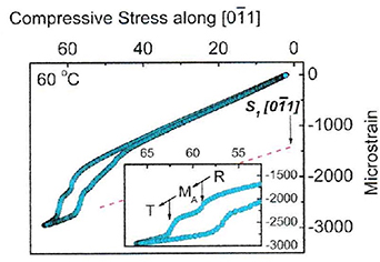
Figure 11. Uniaxial compression–decompression response at 60 °C, note the two successive transitions near 55 MPa compression (inset) [34].
Download figure:
Standard image High-resolution imageThe 33-mode stability of domain engineered single crystals with macro-symmetry 2mm (2R 33 mode) under compressive stress and field revealed some unexpected results [35]. The observed anomaly near 50 MPa compressive stress in figure 12(a) was attributed to a FE rhombohedral FR–FE tetragonal FT transition. On decompression, however, the FT state remained stable and did not revert back to the initial FR. The phase transition from FR to FT under compression proceeds by the rotation of the 2R polarization vectors in the mirror symmetry plane leading to a final stable FE tetragonal FT state, having the polarization vectors along the ± [100] symmetry axis. The FT state is comprised of 180° tail-to-tail charged domain walls that remain stable after decompression. Using the values Q11, = 0.066 m4 C−2, Q12= −0.032 m4 C−2, and Q44 =0.015 m4 C−1 for the electrostriction coefficients [17], and 0.24 C m−2 for PR, as determined from a room temperature hysteresis loop measurement, the calculated strain associated with FR − FT phase transition is: SR–T [011] = −0.5(Q11 − Q12 − 2 Q44) PR 2 = −1958 micro strain, in a reasonable agreement with the experimental observation of ∼−2200 micro strain in figure 12(a).

Figure 12. (a) Room temperature, zero field uniaxial compression–decompression response of the 33-mode PMNZT (60%PZT) crystal with macro-symmetry 2mm (2R 33 mode). The observed anomaly near 50 MPa compression is attributed to an irreversible FR − FT transition (b) strain-field response at different pre-stress levels, note the null strain response for the 62 MPa compression due to the induced 180° domain structure [35].
Download figure:
Standard image High-resolution imageThe strain-field response under different pre-stress levels is depicted in figure 12(b). For pre-stress levels up to 41 MPa the response remained linear, with a piezoelectric coefficient d33= 1121 pm V−1 as calculated from the strain derivative with respect to field. At a pre-stress level of 62 PMa, which is sufficiently large to stabilize the FT state with 180° tail-to-tail charged domain wall structure (net zero polarization,) the strain derivative with respect to field is zero up to a field level ∼0.5 MV m−1 and the FR state becomes stable for fields >0.5 MV m−1. The 33-mode stability under compressive stress and field of domain engineered single crystals fabricated from a ternary PINMT composition, with macro-symmetry 2mm revealed similar behavior as shown in figures 13(a) and (b).
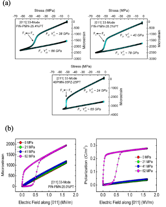
Figure 13. (a) Room temperature, zero field uniaxial compression–decompression response of the 33-mode PINMT (28% PT) crystal with macro-symmetry 2mm. The observed anomaly near 50 MPa compression is attributed to an irreversible FR − FT transition (b) strain-field response at different pre-stress levels, note the null strain response for the 62 MPa compression due to the induced 180° domain structure [35].
Download figure:
Standard image High-resolution imageThe role of charged domain walls in driving the reversible inter FE FR − FO transition is evident in the 33- and 32-modes with 4mm (4R 33 mode) and 2mm (2R 32 mode) macro symmetries. However, this is not the case for the 33-mode geometry with 2mm macro symmetry (2R 33 mode) as demonstrated in crystals fabricated from two different ternary systems, i.e. PMNZT and PINMT. In both systems, a uniaxial compression causes the 2R domain state to rotate in the mirror symmetry plane, leading to a stable 180° tail-to-tail (2T) domain state, under free electric and elastic boundaries. This is further discussed in the conclusion.
2.3. Transduction modality near inter-FE instability in domain engineered single crystals
Transduction modality near an inter-FE instability in domain engineered single crystals was developed by Finkel et al nearly a decade ago [36, 37]. The motivation was to harness the large strain and polarization changes associated with inter-FE transitions in domain engineered crystals using low drive field or low mechanical excitation. For practical purposes, the choice was to further investigate this modality in the 2mm domain engineered ternary PINMT single crystals configured in the 32-mode geometry (2R 32 mode). Figure 14 illustrates the uniaxial compression–decompression response at several dc bias fields of domain engineered PINMT single crystal configured in the 32-mode. The basic idea is to mechanically clamp the crystal just below the critical stress (10 MPa at 0 bias) that is required to induce the for FR − FO transition. At this bias stress level, small oscillations in stress will drive the crystal in and out of the transition. Alternatively, referring to the three-dimensional diagram (figure 9), bringing the FR state to any point close to phase boundary surface, e.g. by a mechanical compression, makes it possible for small mechanical, electrical, or thermal oscillations to drive the crystal through the transition cycle FR − FO −FR. The associated large output can, therefore, be harnessed by a proper circuit design.

Figure 14. Isothermal (20 °C) uniaxial compression–decompression response with and without dc field. Left inset shows the crystal orientation, uniaxial stress, and the electric field directions for the 32-mode drive. Right inset shows a plot of the intermediate isothermal compressive stress vs. electric field levels responsible for FR − FO transitions [36].
Download figure:
Standard image High-resolution imageThe drive field and generated strain for the 32-mode PINMT single crystal have been investigated as a function of loading rate. A 5000 micro-strain amplitude oscillation was generated under a drive field frequency of 1–2 Hz, and amplitude ∼0.1 MV m−1 as shown in figure 15(a). The crystal withstood continuous drive sweeps, either harmonic or rectangular field ramp (figure 15(a) inset), switching for nearly 105 cycles before it fractured. Compared to the results of Shrout and Park [3, 4] in figure 2(a), the present drive field is more than an order of magnitude lower. A compact flextensional low frequency, high source level sound projector using the transduction modality near inter-FE instability in PINMT is shown in figure 15(b).
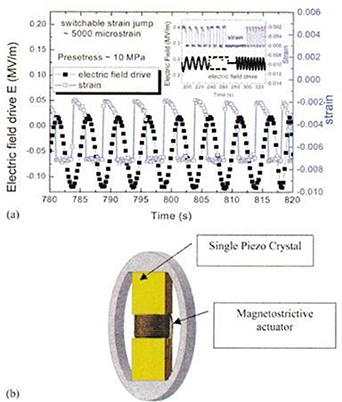
Figure 15. (a) Time dependent plot of the strain and electric field in PINMT domain engineered single crystal under pre-stress 10 MPa and small negative dc bias field for various electric field drive conditions. (b) Class IV flextensional low frequency, high source level sound projector using the transduction modality near inter-ferroelectric instability in PINMT. The magnetostrictive actuator provides stress compensation for changes in temperature and hydrostatic pressure (End caps and waterproof boot are not shown.) [36, 37].
Download figure:
Standard image High-resolution imageIn another development, Dong et al demonstrated the outstanding energy harvesting capabilities of this transduction modality [38, 39]. This promising performance gain of has been demonstrated in other device concepts. This is the subject of the next sections.
2.4. Recent advances in high coupling single crystals
The effort in crystal growth of high electromechanical coupling crystals has been focused on four main compositions, namely, binary or pseudo-binary morphotropic FE rhombohedral FR such as PMNT, PZNT, PMNZT, and more recently, the CFB growth of ternary PINMT. The CFB method provides significant improvements in (1) compositional uniformity, both in-plane and axial, over large size boules, (2) stability of the electromechanical properties under compressive stress, large drive, and temperature, and it promises the potential of cost reduction.
The small signal electromechanical properties of 33- and 32-modes bars fabricated from a 28 mole % PT morphotropic composition are listed in table 1. A three-dimensional representation of 32-mode stability of 2mm domain engineered PINMT single crystals (2R 32 mode) in the stress-temperature field parameter space [40] is depicted in figure 16.
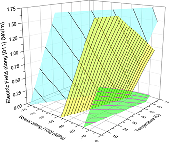
Figure 16. Three-dimensional representation of 2R 32-mode stability (2mm domain engineered) PINMT single crystals in the stress-temperature field parameter space. This figure is modified from [40] to include the 29.90% and 25.40% PT compositions. The shaded surfaces from left to right represent compositions with PT contents 25.40%, 28.00% and 29.90% respectively.
Download figure:
Standard image High-resolution imageTable 1. Room temperature small signal electromechanical properties of PINMT single crystals grown by continuous feed Bridgeman (CFB)-average of five bars [40]. Numbers between () in the above table represent the standard deviations in the least significant digit(s).
| k33 0.90 (1) | d33 (pC/N) 1228 (26) | YE (GPa) 19 (1) | K 4051 (156) | T RT (°C) 118 (3) |
| k32 0.878 (4) | d32 (pC/N) 1309 (34) | 1/s22 E (GPa) 13 (1) | K 3372 (120) | T RT (°C) 118 (3) |
2.5. Antiferroelectric (AF)–ferroelectric (FE) and ferroelectric (FE)–paraelectric (PE) modalities
The AF–FE and the FE–PE modalities have been demonstrated to significantly enhance some applications. These applications are briefly discussed as they have relevance to the interphase modalities of the relaxor single crystals. The AF–FE transduction in modified polycrystalline lead zirconate titanate stannate to generate large strain was discussed in [41, 42]. This modality does not rely on bringing the AF state close to instability using a bias stress prior to triggering the transition. Instead, the transition is triggered by applying a significantly large field to the AF state that induces the FE state in compositions just to the AF side of the phase boundary. Pan, Zhang, Bhalla, and Cross [42] have demonstrated in modified lead zirconate titanate stannate, strain levels up to 0.85% at fields ∼6 MV m−1. This drive level is ∼30 times larger compared to the field required to generate the same strain level in domain engineered crystals poised near an inter FE transition.
The FE–PE transduction modality was motivated by the need for inexpensive, compact, uncooled, handheld IR imaging systems in the medium wavelength range 7.5–14 m, corresponding to the thermal black body maximum near room temperature. Bandgap infrared (IR) detectors such as mercury cadmium telluride operate at low temperature around 77 K to obviate thermal noise, they require cooling systems, and they are expensive. This modality utilizes the pyroelectric effect near a FE–PE phase transition where it is maximum. The vertically integrated technology for system production utilizing this modality was pioneered in the 80s and 90s by GEC Marconi in the United Kingdom using polycrystalline FE lead scandium tantalate (PScT) and Texas Instruments (TI) in the United States using polycrystalline FE barium strontium titanate (BST).
We briefly describe the TI hybrid approach [43–45]. This approach relies on the large polarization change with temperature (pyroelectricity) of a poled and biased FE material (BST) poised near its FE–PE transition temperature TC (Curie temperature). Figure 17(a) shows the polarization change with temperature and the pyroelectric response of FE barium strontium titanate (BST) wafer with a Curie temperature TC near room temperature ∼23 °C. The wafer is biased at 2.5 V/mil (0.1 MV m−1) to prevent depoling. The detector consists of a densely populated two-dimensional focal plane array fabricated from BST pixels (320 × 240) on a size scale 50 × 50 × 25 μm3 per pixel, directly bonded to the readout integrated circuit (ROIC) as shown in figure 17(b). Figure 17(c) shows the array implementation of pixel unit cells, where each pixel is represented by a capacitance connected to a CMOS inverter pre-amplifier with a large feedback resistor, a gain stage, and address switch.
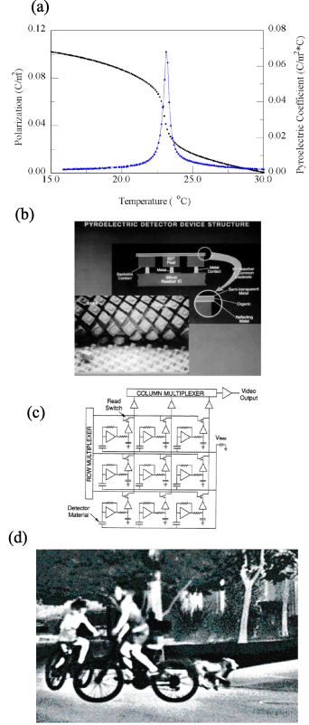
Figure 17. (a) The pyroelectric coefficient (blue line,) and the spontaneous polarization (black line) of a BST wafer biased at 2.5 V/mil (0.1 MV m−1), (b) a schematic of the detector structure showing the BST pixels, the backside contacts, the polymer mesa (for thermal isolation), the readout silicon IC, IR absorber, and the common electrode (top). A peel off SEM of an actual detector is shown in the bottom portion, (c) read out integrated circuit ROIC showing array implementation of detector unit cells (see text), (d) image from a video taken by a hand-held uncooled BST infrared video camera [43–45].
Download figure:
Standard image High-resolution imageAn antireflection Ge window covers the package and allows IR transmission in the range 7.5–14 m spectral region. An IR lens projects the IR image on the focal plane array. The array is mounted on a thermoelectric cooler for optimum operation near TC, and a chopper provides thermal modulation at 30 Hz. The ROIC filters, amplifies, samples, and multiplexes the detector signal one row at a time, and delivers the output at a standard RS 170 rate. The imaging system (handheld, helmet, or dashboard mounted) operates at room temperature, thereby eliminating the need for cryogenic cooling. A useful measure of the system sensitivity is the noise equivalent temperature difference (NETD). This is the temperature difference at the scene ΔTscene, required to generate an rms signal-to-noise (S/N) ratio = 1. An impressive NETD of less than 0.02 K was achieved.
Transduction modality near an instability in domain engineered single crystals provides a significant advantage for generating large strain at a much lower field when compared to the traditional linear-mode piezoelectric and the AF–FE transduction modalities. For applications in infrared point detectors and thermal imaging arrays, its benefit is not well established, simply because of the lack of experimental data. The large polarization change associated with the FR − FO transition, and the FR − FT transition, that can be triggered by small oscillations in mechanical stress, electric field, or temperature, provides the potential for their applications in IR imaging technology. Unlike BST imaging arrays, the requirement for dc bias is obviated.
3. X-ray diffraction and synchrotron investigation under mechanical compression and electric field of domain engineered 32-mode single crystals with macro-symmetry 2mm (2R 32 mode)
3.1. X-ray diffraction and reciprocal space mapping
In this section x-ray diffraction studies are reviewed. These include studies of domain engineered single crystals under the combined application of mechanical compression and electric field [46], and recent grazing incidence [47] and synchrotron investigation using high brilliance high resolution beam [48]. The diffraction experiment geometry and frames of references are depicted in figure 18. The diffraction circle for the  , and the
  scan-modes (reciprocal space mapping) is shown. The measurement reference frame (X1, X2, X3) is depicted in figure 18 bottom along with the crystallographic axes of the domain engineered [011] poled, 32-mode single crystal with (macro-symmetry 2mm). The applied electric field E3 and the uniaxial compression
  directions are marked. The two FE rhombohedral FR variants Pr [
 11] and Pr [111] under free elastic and electric boundaries are depicted on the upper left. Note, the original pseudo-cubic <100> axes are taken such that the [001] axis is along X3, and the right-handed coordinate system is completed with X1 and X2 along the [100], and [010] respectively. The mono-polarized FE orthorhombic state FO under E > EC, or
  is shown on the upper right.

Figure 18. The diffraction experiment set-up showing the relationship between the crystallographic axes, electric field and compressive stress directions, and the incident and scattered beam directions for the  and the
  (reciprocal space mapping) scan-modes, see [46].
Download figure:
Standard image High-resolution image
 x-ray diffraction scans were conducted using Cu Ka radiation for a [011] poled PINMT single crystal, with ∼29% PT content on the rhombohedral R3m side of the MPB. The diffraction pattern in figure 19(a) is taken with 19 MPa compression and 0 MV m−1 field applied to the crystal (sufficient to induce the FR − FO transition). The red trace is that of the FO state (040) and (400) reflections. The application of −0.18 MV m−1 electric field was sufficient to pull back and stabilize the FR state, as demonstrated by the rhombohedral (220) and (202) reflections (blue trace.) The integrated intensity of the rhombohedral (220) and the orthorhombic (040) peaks scanned at 19 MPa compression (the critical stress) as a function of ±0.20 MV m−1 harmonic drive field are shown in figures 19(b) and (c). The results clearly demonstrate the switching between the FR and the FO states as the crystal being cycled by the electric field under compression. The electric field dependence of the rhombohedral lattice spacing d (220) and the orthorhombic d (040) is shown in figure 19(d), both states behave as linear piezoelectric.
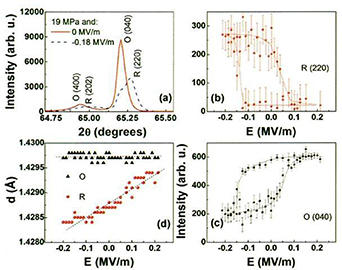
Figure 19. (a) The diffraction profile of the scanned peaks of the FR and FO states under compression (with and without field), (b) and (c) the integrated intensity of rhombohedral (220) and orthorhombic (040) vs. field, (d) the rhombohedral and orthorhombic d-spacings vs. applied electric field [46].
Download figure:
Standard image High-resolution imageReciprocal space maps figure 20(a) of the pseudo-cubic (0 2  ) reflection at 0 MPa clearly show the crystal to be predominately rhombohedral, with two clear (220) and (2 0
  ) reflections. At 20 MPa the two rhombohedral variants of the domain engineered crystal collapse into one in the orthorhombic state, with the (040) and (040) reflection present. The mono-polarized orthorhombic state has its polarization vector along the orthorhombic a-axis, the X3 direction as shown in the upper right corner of figure 19(a) The calculated lattice parameters of the FE rhombohedral state at 0 MPa are a = 0.404 16 (7) nm and α = 89.87 (3). And those of the FE orthorhombic state at 20 MPa are, a = 0.574 96 (11) nm, b = 0.571 804 (3) nm, and c = 0.401 76 (59) nm, the numbers between () represent the standard deviation in the least significant digit(s).
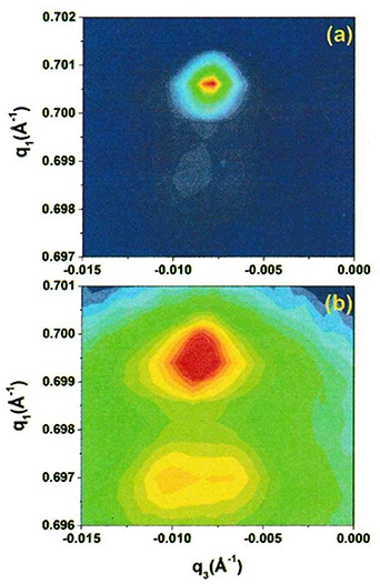
Figure 20. Logarithmic representation of reciprocal space maps of the cubic (02−2) reflection (a) at 0 MPa, the sample is predominately rhombohedral with two clear (220) and (20–2) reflections and (b) at 20 MPa the crystal is in the orthorhombic state with the (040) and (040) reflection present. The small second peak indicates the onset of twinning. The deviation of q3 from zero is indicative of a small miscut in the sample [46].
Download figure:
Standard image High-resolution imageThe axial strain along X2, and the transverse components along X3 and X1 for the Fo state (macro symmetry 2mm) are displayed versus the ±0.20 MV m−1 harmonic drive field in figure 21(a) at 19 MPa compression. The crystal exhibited a slight fatigue after ∼40 million cycles (inset). The volume fraction of the FO phase is depicted in figure 21(b), this is qualitatively similar to the x-ray intensities of figure 19(c). Figure 21(b) confirms that the entire crystal transforms cooperatively between FO and FR. Arguably, the volume fraction cannot be negative as shown in the region below the zero crossings in figure 21(b). This negative portion of volume fraction is attributed to the simple model used in the calculation with experimental data input. A more involved model would need to account for domain shape and propagation.

Figure 21. (a) Measured bulk strain at 21 MPa as a function of the applied field. Inset: electrically driven strain at 19 MPa before and after ∼40 million cycles through the FR − FO phase transition. (b) Volume fraction of the orthorhombic phase as a function of the applied field to a mechanically biased FR crystal at 19 MPa [46].
Download figure:
Standard image High-resolution imageThe Gibbs free energy difference at free boundaries  G between the FE rhombohedral FR and orthorhombic FO states, can be written in terms of the energy difference components near the critical stress (19 MPa) and field (0.18 MV m−1) as follows,

The first term in the right-hand side is due to the polarization difference between the orthorhombic and rhombohedral states. The second, third, fourth, and fifth terms are the dielectric permittivity, piezoelectric, transition strain, and elastic contributions respectively. The calculated ΔG of ∼0.07 × 10⁶ J m−3, is in the same order of magnitude as that derived from a modified Devonshire theory for morphotropic PZT compositions [17]. Such a small difference in energy accounts for the agility of the FR − FO inter-FE transition by an electric field, mechanical stress, or a combination of both. The transition from a macro-polarized FR ensemble to a mono-polarized FO state occurs via polarization rotation in a symmetry (mirror) plane of the two rhombohedral variants. Because the mono-polarized FO state is not stable under free elastic or electric boundaries, it reverts back to the original macro-polarized FR ensemble (lower energy state) upon the release of the applied field and/or the mechanical stress. The calculated latent heat ΔQ from the Clausius equation is ![$\Delta Q = T\Delta S = T\Delta \varepsilon \,{\left[ {\partial {\sigma _{\text{C}}}/\partial T} \right]_{\text{E}}} = T\Delta P{\left[ {\partial {E_{\text{C}}}/\partial T} \right]_\sigma }$](https://content.cld.iop.org/journals/0964-1726/33/1/013001/revision2/smsad06deieqn24.gif) = 1.5 × 10⁵ J m−3, in a close agreement to theoretical values [18, 19].
= 1.5 × 10⁵ J m−3, in a close agreement to theoretical values [18, 19].
Application of either mechanical stress along X2, or electric field along X3 will lead to a slight monoclinic distortion (MB or MC) of the rhombohedral symmetry, via polarization rotation in symmetry planes. Upon further increase of the loading, the final state will be orthorhombic. The monoclinic distortion is below the resolution limit of the present x-ray diffraction system. Further experiments using a high resolution-high brilliance Synchrotron source have overcome this obstacle and revealed some interesting results as explained below.
3.2. Grazing incidence diffraction and synchrotron results
The diffraction pattern of pseudo symmetric structures such as FEs is characterized by partial overlap of diffraction maxima. This is due to the relatively small strain associated with the PE–FE phase transition. Relaxor FEs such as PMNPT pose an additional problem due to the broad nature of the Bragg peaks. The existence of a strained surface layer with different property and or symmetry from the bulk crystal, or ceramic, because of mechanical processing, such as griding, or polishing has long been known [49–51]. For instance, early x-ray diffraction studies of polycrystalline tetragonal barium titanate by Subbaro et al [49], demonstrated the drastic effect of polishing on the reorientation of 90° ferroelastic domains. Almost a complete switching of c- to a- domains occurred as deduced from the diffraction pattern. A subsequent diffraction study by Amin et al [50], on semiconducting FE barium titanate confirmed the same. Additionally, extensive plastic deformation of barium titanate because of grinding was inferred from x-ray line broadening and the FE–PE transition temperature [51]. Furthermore, symmetry and structural information from a diffraction experiment are limited by the penetration depth of x-rays, which is only a few tenth of a micron below the crystal surface. Therefore, it may be difficult in many cases to deconvolute the diffraction pattern to unequivocally deduce the correct symmetry of the crystal. There is a plethora of publications in the open literature that address these issues in relaxor-FE single crystals using x-ray and synchrotron diffraction. We summarize below the results from two recent diffraction experiments under the application of electric field and mechanical stress.
In situ electric field study of surface effects in domain engineered [011] poled rhombohedral PMNPT by grazing incidence x-ray diffraction was conducted by Finkel et al [46] In this study the diffraction data was collected as a function of depth (up to 0.2 µm below the surface), electric field, and temperature. The d-spacing of the probed hkl reflections were calculated from the measured peak position, assuming a pseudo cubic structure with lattice parameter 0.4040 nm. The results showed that at depth up to the maximum accessed (∼0.2 µm), the d-spacings were below and have not reached the bulk value. This is indicative of a strained surface layer, with a strain gradient across. For instance, based on d (010) measurements at 40 °C, the strain varied from ∼0.5% at a depth of ∼0.005 µm to ∼1% at ∼0.200 µm below the surface. The measured depth dependence of the d-spacing of selected reflections, and strain calculation as a function of field, identified those planes which have a higher sensitivity to field, hence providing an opportunity for strain optimization in devices such as energy harvesting and magnetoelectric (ME) composites. Recent synchrotron and optical investigation by Finkel et al [48] of domain engineered [011] poled rhombohedral PINMPT single crystal demonstrated that near a compressive stress of 30 MPa the two rhombohedral twins transformed to a twined monoclinic MB structure based on symmetry arguments. At a higher compressive stress, the twins collapsed to a single phase dubbed M* which could be described by a monoclinic symmetry. Finally, one should keep in mind, as discussed earlier, that structural information derived from x-ray diffraction is penetration depth limited to a few microns below the crystal surface. Penetration depth calculations for PZNT domain engineered single crystals showed that the x-ray intensity drops to only 10% of the incident intensity at a depth of 15 µm from the surface, giving rise to a penetration of 10–20 µm [52].
4. Ideal thermodynamic cycle for energy harvesting
A thermodynamic cycle for energy harvesting using FE materials was established from the rate external work is done on the material, either mechanically or electrically, the rate heat is added to the material from external sources, and the rate heat is generated by dissipative processes. In the ideal cycle, dissipation is neglected. This framework is used for the identification of cycles that can be used for the conversion of mechanical work into electrical energy, and thermal energy into electrical energy; and for assessment of the effects of the material losses that generate heat.
4.1. Work done by external forces, internal energy, dissipation, and constitutive laws
Piezoelectric materials can be used to convert mechanical work to electrical energy. Mechanical work is done when a force is applied to a surface of the crystal. As the crystal surface displaces, the force acting over a displacement does work. Forces on a surface are expressed as tractions (force per unit area), and the rate mechanical work is done is given by equation (4.1),
where  is the rate work is done by the mechanical force as the surface displaces (J s−1).
  are the components of the traction vector (N m−2) and are equal to the dot product of the stress tensor just beneath the surface with the unit normal to the surface.
  ,
,  are the corresponding displacement rate vector components (m s−1), and
  is the surface area (m2). The work done in a loading and unloading cycle is found by integrating equation (4.1) over the period of the cycle. The work rate is written in terms of a volume integral by substitution of the stress and unit normal, and use of the divergence theorem. When the material behavior is rate independent, the rates can be replaced with increments; and when it is path independent (no hysteresis, a good example being linear elastic), the work done can be written in terms of the end points of the path. This gives equation (4.2) where the final term comes from the linear elastic case where
  and
and  are the components of the stiffness tensor,
Consider applying a compressive load cycle to a linear elastic material. Positive work is done in the loading half of the cycle (work is done on the material by the load), and an equal amount of negative work is done during the unloading cycle (work is done by the material on the load). The work done in the loading half of the cycle is the area under the load–displacement curve and the work per unit volume is the area under the corresponding stress–strain curve. The amount of work done on the loading half of the cycle to a given maximum load depends on the stiffness. Less work is done on a stiffer material because the resulting displacement and strain components are smaller. Upon unloading, work is done by the material on the load. The work done on a linear elastic material in a closed loading–unloading cycle is zero.
Electrical work is done on a material by moving surface charge from one location on the surface to another in the presence of an electric potential difference between those two points. The rate electrical work is done on the material,  (J s−1), is given by equation (4.3)
where  is the electric potential (V) (recall one volt is one Newton-meter per Coulomb or Joule/Coulomb), and
  is the rate surface charge density is changing (C m−2s−1). The surface charge density is equal to the normal component of electric displacement,
  . With this substitution, using the divergence theorem, and assuming rate and path independence, gives equation (4.4),
Equations (4.2) and (4.4) are used to identify ideal loading paths for mechanical energy harvesting using piezoelectric materials.
A linear piezoelectric material has a higher stiffness under open circuit conditions, denoted  , than under short circuit conditions because charge cannot flow during open circuit loading. This generates a back electric field that restricts the mechanical displacement via the piezoelectric effect. Under short circuit loading the stiffness is lower, denoted
  , because charge flows and the displacement is not restricted by a back electric field. Figure 22 illustrates an ideal loading cycle for converting mechanical work to electrical work. In this cycle, the material is loaded under open circuit conditions. The material is loaded mechanically, O-A in figure 22(a). This induces an electric field in the material, O-A in figure 22(b). Next, electrical work is done as the charge is drained into a circuit (A-B in figure 22(b)). The material mechanically displaces at constant stress (A-B in figure 22(a)). Additional mechanical work is done during this displacement. The material is then mechanically unloaded under open circuit conditions (B-C), and electrical work is again done as the charge is drained (C-O) as depicted in figure 22(b). In this ideal case, the area within the two curves is identical. The mechanical loop is traversed clockwise, corresponding to work being done on the material. The electrical loop is traversed counter clockwise, corresponding to electrical work being done by the material on a circuit.
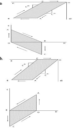
Figure 22. (a) The mechanical clockwise loading path OABCO for a linear piezoelectric under an ideal energy harvesting cycle is the work per volume done on the material and has an enclosed are equal to figure (b), the area within the electrical path corresponding to the energy extracted per unit volume in the electrical cycle.
Download figure:
Standard image High-resolution imageIn developing these idealized cycles it was assumed that there is no material hysteresis (loss) and that the material behavior is rate independent. In general, neither assumption is valid for FE materials. Upon changing the load, either electrically or mechanically, domain walls move. This can be accompanied by some diffusion of charge carriers. This results in material hysteresis affecting the loading cycle. The hysteresis shows up as heat being generated. Under sinusoidal loading it is often represented as a loss tangent ( ). Relaxor FE crystals are domain engineered to minimize the driving force for domain wall motion. This results in the material being very low loss.
When the material behavior is dissipative, heat is generated as either a stress or an electric field is cycled. Under cyclic loading, this heat will build up unless it is removed through convection, conduction, or radiation. The dissipative processes in oxide FEs are generally related to domain wall motion and a small amount of local electrical conduction. In the case of phase transformations this can be associated with losses in the process, or a difference in energy reversibly stored within the different crystal structures (enthalpy of transformation).
As discussed in section 1, part E, loading relaxor FE single crystals in the vicinity of a phase transformations can enhance the magnitude of the electro-mechanical energy conversion. This is discussed for both the [001] cut (4R 33 mode) and the [011] cut (2R 32 mode). Sufficiently high compressive loading of the [001] cut and poled crystal in the <001> direction drives it from the 4R symmetry to the 4O symmetry. This reduces the polarization from the initial remanent polarization of around 0.38 C m−2 to near zero polarization, a very large polarization change in a single cycle. The effect is different in the [011] cut and poled crystal. A sufficiently high compressive loading of the [011] cut and poled crystal in the [100] direction drives it from 2R symmetry to 1O symmetry. This increases the polarization in the <011> direction.
Idealized open circuit and short circuit loading and unloading curves are shown for the [011] cut in figure 23 with the mechanical loading along the [100] direction and the polarization along the [011] direction. Under short circuit loading and unloading there is a phase transformation from 2R to 1O and back to 2R. This phase transformation produces a hysteresis loop in the loading–unloading curve that is shown as the white shaded area in figure 23(a) associated with loading path O-A'-B'-C'-E'-A'-O. In this crystal cut, compressive stress increases the polarization. Under open circuit loading, the back electric field that opposes the polarization change under open circuit conditions is positive for compressive loading and negative for compressive unloading.
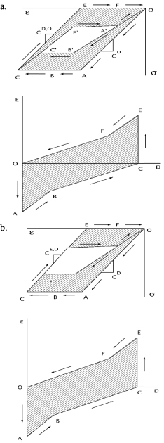
Figure 23. (a) The area within the path OABCEFO is the mechanical work per unit volume done on the material during the ideal energy harvesting cycle shown in (b). The area within path A'B'C'E'A' is the material loss to hysteresis under short circuit conditions. The material loss associated with domain or phase boundary motion corresponds to temperature increase. The shaded area in (a) corresponds the energy harvested per unit volume shown in the electric displacement vs. electric field plot of figure (b).
Download figure:
Standard image High-resolution imageThe ideal energy harvesting cycle with a phase transformation present involves loading the material under open circuit conditions (path O-A) allowing electrical work to be done by the linear piezoelectric effect (path A-B), allowing additional electrical work to be done by the phase transformation (path B-C) unloading under open circuit conditions (path C-E), and again allowing electrical work to be done by the linear piezoelectric effect and the reverse phase transformation (path E-F-O) as shown in figures 23(a) and (b). The shaded area in figure 23(a) is equal to the shaded area in figure 23(b) and represents the energy per unit volume converted from mechanical to electrical.
This R-O phase transformation is temperature dependent. As the material is cycled and heats up, the threshold for the forward and reverse phase transformations change. A brief discussion of heat added and heat generated by dissipative processes provides insight into self-heating and keeping the material or device cool.
The addition of heat from external sources or from internal heat generation results in an increase of temperature and entropy of the material. The rate of thermal energy added to the material, (J) is given by equation (4.5)
where  (J m−3) is the rate of thermal energy addition from external sources per unit volume,
  (J m−2) are the vector components of the outward heat flux, and
  are the components of the unit normal to the surface. The negative sign is to account for thermal energy being added to the material.
The rate work is done on the material plus the rate heat is added are equal to the rate of increase of the kinetic and internal energy of the material.
The expression for energy balance is given by equation (4.6)

where  is the rate of increase of kinetic energy, and
  is the rate of increase of internal energy. Energy can be stored within a material as strain energy, electrical energy, thermal energy, or configurational energy. In the relaxor FE single crystals, the configurational energy included domain wall energy that changes with domain wall density, and energy associated with different crystal structures when phase transformations take place.
Upon substitution, the energy balance is written as equation (4.7)
where  is the mass density and
  is the internal energy density. The traction vector is written in terms of the stress and the unit normal, and the surface charge density is written in terms of the electric displacement and the unit normal to give equation (4.8)
The divergence theorem is applied to convert the surface to volume integrals, a comma in front of an index indicated the partial derivative with respect to that index, mechanical equilibrium,  , and quasi-static charge equilibrium,
  , are applied, the internal displacements are assumed to be homogeneous such that
  , and the resulting volume integral is reduced to equation (4.9)
Relaxor FE single crystals have very low electrical conductivity, and in energy harvesting applications they are typically used well below their resonant frequency such that body charges and body forces can be neglected. In the absence of body forces and body charges this reduces to equation (4.10)
Shrinking the volume to a small enough size that the fields within can be treated as uniform, yet large enough that there can still be domains within the volume as long as the volume is large enough that it is a good representation of the volume average behavior leads to equation (4.11)

This expression is valid even when the strain and electric displacement increments contain irreversible (dissipative) terms. This includes strain and polarization changes associated with domain wall motion or phase boundary motion where the domain wall motion generates heat, and similarly strain and polarization changes associated with phase transformations where there may be elimination of domain walls and generation of new domain walls as the crystal transforms from a rhombohedral structure to an orthorhombic structure and back. This annihilation and regeneration of the domain structure in the rhombohedral phase may be a contributor to the hysteresis in the phase transformation from a rhombohedral engineered 2R domain structure to the electric field or stress induced orthorhombic 1O single domain single crystal structure. Evidence of the evolution of the domain structure during this phase transformation is shown in figure 24, from Liu et al [53].
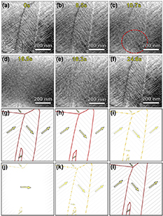
Figure 24. This micrograph shows the disappearance of the domain structure as the material undergoes a field driven phase transformation from a 2R to a 1O state, and a reappearance of the domain structure upon unloading. Acta Materialia 175 (2019) 436e444.
Download figure:
Standard image High-resolution imageThe second law of thermodynamics states that the increase of thermal energy within any volume of material is always greater than or equal to the rate heat is being added from external sources, equation (4.12)

where  , thus the rate of generation of thermal energy is either equal to or exceeds the rate of heat addition, equation (4.13),
When some portion of the strain rate and electric displacement rate are dissipative (open hysteresis loops), some of the external mechanical and electrical work generate heat within the material and is not available for harvesting. Further insight is gained by separating the strain rate and electric displacement rate into a reversible part and an irreversible part, equations (4.14) and (4.15)


Substituting these into the energy equation gives equation (4.16)

where, upon substitution, the increase of internal energy is given by equation (4.17)

where  is the rate of entropy generation per unit mass. The rate of increase of thermal energy is thus given by equation (4.18)

In an adiabatic process (no heat transfer to or from the surroundings), the last two terms of equation (4.16) (the external heat added) are zero. The first term is the stress operating on the irreversible portion of the strain rate, and the second term is the electric field operating on the irreversible portion of the electric displacement rate. These are equal to the rate of thermal energy generation by dissipative processes. Just as the extraction of electrical energy during a cycle gives a hysteresis loop in the mechanical loading cycle, the conversion of mechanical or electrical energy to thermal energy results in hysteresis in the mechanical and electrical cycles. Under short circuit loading where there is no electrical work done, the area within the stress–strain hysteresis loop that occurs in a loading–unloading cycle is equal to the heat generated. In the domain engineered crystals under either [001] (4R 33 mode) or [011] (2R 32 mode) compressive stress loading, there is minimal driving force for domain wall motion as long as the stress and electric field are small enough that there is no field induced phase transformation. This is the reason the crystals have very low loss. In driving the 32 mode crystals through the phase transformation with a [011] electric field or a [100] compressive stress, the domain walls associated with the rhombohedral system are eliminated during the forward FR − FO phase transformation and then regenerated during the reverse FO − FR transformation. This is likely part of the hysteresis that is associated with the phase transformation.
5. Mechanical energy harvesting
This section provides a review of the use of relaxor single crystals for energy harvesting, with emphasis on the enhanced energy per cycle that can be achieved by operating across the R-O phase transformation. Mechanical work can be converted to electrical energy through the linear piezoelectric effect. Liu et al have provided a general review of piezoelectric energy harvesting [53] that summarizes the many geometric configurations of energy harvesters, a broad range of length scales from sub-micron to macroscale, and the use of induced non-linearity through magnetic forces and buckling behavior to enhance the effect. Certain energy harvester designs take advantage of the linear properties of relaxor single crystals in the R phase. Ren et al developed a 4R 33 mode composite energy harvester comprised of [001] relaxor single crystal rods in a soft polymer matrix [54]. Yang et al provided a detailed analysis and demonstrated the capability of a flextensional energy harvester [55]. Song et al demonstrated a unimorph energy harvester by laminating a single crystal plate to the surface of a cantilever beam [56]. This configuration takes advantage of the auxetic behavior of the 2R 32 mode crystal where positive charge is generated by extension of the plate in one direction and contraction in the other direction. This behavior matches the Poisson's ratio effect at the surface of a beam in the anticlastic deformation regime. Gao et al compared a PMNZT ceramic to PMNT relaxor single crystals in a flextensional arrangement [57], making the case that, in the linear regime, a ceramic can produce output comparable to single crystals. Doughney et al [58] developed an energy harvester for use on a gearbox of a helicopter at 1900 Hz. Yu et al [59] demonstrated relaxor single crystal energy harvesting where the composition was modified for stability at elevated temperature.
The electrical energy density produced per cycle is substantially larger when relaxor single crystals are mechanically driven through the rhombohedral to orthorhombic (FR − FO) phase transformation by compressive stress. The large transformation strain results in more mechanical work being done on the material in each cycle, and the coupling of the transformation strain to polarization results in the ability to convert this mechanical work to electrical energy. Dong et al [59] performed a set of experiments on 2R 32 mode [011] cut and poled single crystals to demonstrate this effect. Compressive stress was applied in the [100] direction of a crystal poled in the [011] direction. A baseline was established by mechanically driving the crystal through the phase transformation under short circuit conditions using a stress cycle from −14 to −25 MPa while monitoring strain. This produced the open hysteresis loop shown in figure 25(a). The transformation strain was over 2500 microstrain. The area within this hysteresis loop corresponds to the amount of mechanical work done on the crystal per unit volume that is converted to thermal energy density per cycle. After establishing this baseline, an ideal energy harvesting cycle was run. This ideal cycle was realized using a mechanical switch to alter the open circuit and short circuit conditions.

Figure 25. (a) Mechanical work done when loading a 2R 32 mode specimen under short circuit conditions and again under the conditions of the ideal energy harvesting cycle, and (b) the electrical work done on the resistive load in the ideal energy harvesting cycle.
Download figure:
Standard image High-resolution imageThe stress–strain results for the ideal energy harvesting cycle are shown in figure 25(a) and the resulting electric displacement–electric field results are shown in figure 25(b). The stress was increased from −14 to −25 MPa under open circuit conditions. As the compressive stress was increased, the polarization vectors experienced a driving force to rotate from the 2R orientation to the 1O orientation. This is labeled as path A in the figure. When using compressive stress to drive the 2R-1O phase transformation under open circuit conditions, a back electric field is generated that stabilizes the 2R state, schematically indicated by the double arrows in figures 25(a) and (b). The specimen was next short circuited into a 50 MΩ resistor. The voltage was monitored using a series resistor (voltage divider) and the current found from Ohm's law. This was integrated to obtain charge and normalized by the electrode area to obtain electric displacement. Charge transferred between the electrodes through the resistor brought the electric field to zero along path B as electric work was done on the load resistor. The specimen was again open circuited, and the stress was reduced to −14 MPa along path C. Again, a back electric field was generated, this time in the opposite direction that stabilized the 1O polarization orientation. The specimen was then short circuited, and charge flowed in the opposite direction as the polarization returned to the 2R configuration along path D. Electrical work was again done on the resistor. The electrical energy density produced is the area within the hysteresis loop in figure 25(b) in Nm m−3 or J m−3. In the ideal case, this would be equivalent to the area of the larger hysteresis loop less the area of the short circuit hysteresis loop in figure 25(a), i.e. the work done per unit volume on the specimen less the amount of thermal energy density generated in the cycle. The measured transduction efficiency of this cycle was 14%. This relatively low value is possibly due to electrical losses in the circuit, and possibly due to increased heat generation in the material relative to the short circuit phase transformation.
Running an ideal energy harvesting cycle using a switch to alternately open and short circuit the specimen may produce the maximum possible electrical work, but this is not as readily implemented as directly connecting a crystal subjected to a sinusoidal mechanical load to an electrical load. Dong et al measured the electrical energy generation for various resistive loads under a sinusoidal mechanical load [38]. The experimental results demonstrate that the phase transformation can be used to obtain a giant mechanical to electrical energy conversion effect. The phase transformation results in an output electrical energy density per cycle of ∼750 J cm−3 using a resistive load. This is almost two orders of magnitude greater than the energy density per cycle reported for linear piezoelectric materials. The shape of the electric field vs. polarization curves is different from that of the ideal cycle because charge is continuously being transferred between the electrodes through the load. In a simplified analysis, the specimen can be represented as a highly non-linear capacitor. This nonlinearity means the R–C time constant is a function of where the material is in the hysteresis loop. If the capacitance were constant, the discharge cycles along paths B and D in figure 25(b) would display the behavior of a typical RC time constant. The shape of the hysteresis loops under cyclic loading depends on the resistor value as well as the loading rate as seen in figure 26. For the same loading rate, a smaller value resistor decreases the average time constant and reduces the electric field generated. Driving the stress at higher frequency with a fixed resistor value would increase the electric field generated. If the capacitance were constant, impedance matching would be straight forward. Given the dependence of capacitance on where the material is within the hysteresis loop as well as on temperature and composition, a starting point for design might be to use an average capacitance determined from the dielectric constant at zero stress while recognizing that as the material is cycled there will be a large polarization change during the phase transformation that increase the capacitance considerably.
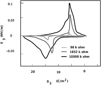
Figure 26. Electric displacement–electric field loops generated by a cyclic compressive stress with the specimen connected to different value resistors.
Download figure:
Standard image High-resolution imageAnother approach used to model relaxor single crystals in energy harvesting applications is to consider the crystal connected to a load to behave as a current source. Dong et al [60] provided data over a range of frequencies and for multiple values of resistive load. In this work, an equivalent circuit consisting of a current source, a capacitor, and a resistor was used to model the results. Moyet et al [61] developed a fixture to apply a mechanical preload while simultaneously applying an oscillating mechanical load to evaluate the energy density produced per cycle and the cycle efficiency over a range of frequencies from 10 to 50 Hz. They used several values of resistive loads in both the linear piezoelectric regime and in the phase transformation regime. They achieved efficiencies in the phase transformation regime as high as 25% with electrical energy density produced per cycle as high as 10 mJ cm3. Dang et al demonstrated a 1.7 kHz energy harvester design [62] using the 2R 32 mode crystal cut that takes advantage of the FR − FO transformation.
The design of energy harvesting systems that involve driving the crystals through this phase transformation requires several considerations. Heat must be removed at the rate it is generated to avoid a steady temperature increase. Higher drive frequency requires a higher heat transfer rate. The hysteresis loops shown in figure 25 demonstrate the effect, but they are dependent on the environment they are subjected to. The threshold stress for the phase transformation as well as the dissipative behavior (area within the loop) are functions of temperature, electric field, and material composition. The dissipative behavior tends to stabilize with cycling as the crystal heats up. Harvesters designed to take advantage of this phase transformation need to operate in a narrow temperature range.
The effect of composition and temperature on hysteresis as the material is driven through the R-O phase transformation was characterized by Gallagher et al [63]. Figure 27(a) shows that decreasing the lead titanate (PT) content reduces the hysteresis in the phase transformation, but it also reduces the electric displacement change and increases the transformation electric field. There is a corresponding increase in the transformation stress. Temperature also affects the transformation threshold stress and electric field levels as is apparent from figure 27(b).
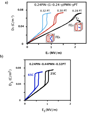
Figure 27. (a) Effect of composition on the phase transformation behavior of PINMT and (b) effect of temperature on the phase transformation.
Download figure:
Standard image High-resolution imageThe effects of composition and temperature on the phase transformation are important design parameters for energy harvesting applications. Composition can be selected to bring the transformation stress and electric fields to lower levels. A reduced transformation stress results in a system that requires a smaller preload. The transformation stress will be further reduced by increases in temperature and may require a feedback system that controls the preload to maintain operation across the phase transformation.
6. Magnetoelectric (ME) and electro-optic effects
ME coupling in composites, where the magnetic moment can be tuned by an electric field or an electric field induced by an applied magnetic field, have shown promise for many different types of novel devices and applications. In contrast to a relatively mediocre ME coupling coefficient in single phase multiferroics, the value of the ME coupling in artificial multiferroic heterostructures can be up to six orders of magnitude larger than ME coupling within a single material, but further advances are needed to enable highly efficient, low energy consumption memory, logic, and magnetic sensors [64]. These composites most often couple a magnetostrictive phase and a piezoelectric phase that are coupled through interfacial strain.
Although rapid advances in the strain-mediated heterostructures have been made in the last several decades, there are still limitations related to the power and difficulties achieving high performance over a broad operational frequency range that currently inhibit the realization of many ME applications [64–66].
In recent years, relaxor FEs have become some of the most popular piezoelectric materials in such ME composites due to the large strains generated through the piezoelectric and electrostrictive effects. An increasing number of papers have highlighted the large values of converse ME coupling that can be achieved with relaxors [67–70] or demonstrated the ability to tune the ferromagnetic resonance with electric field in these composites [71–73]. Studies utilizing the even larger strains generated through a phase transition are scarce, though, due to several challenges including being able to electrically induce a phase transition, transitions away from room temperature, and achieving repeatability in driving through with the electric field.
Studies of La0.7Ca0.3MnO3 and La0.67Sr0.33MnO3 (LSMO) films grown on BaTiO3 showed a sharp decrease in magnetism corresponding to the temperature-induced FR − FO transition near 190 K, with some samples showing a smaller change at the FO − FT transition [74, 75]. A jump in magnetization was also observed for the LSMO film with an applied electric field while held at temperatures near these phase changes. Continued cycling or switching was not established with reversed polarity in this work, and in fact the authors state that repeated measurements were limited by catastrophic failure of the samples. Our own previous work had finally demonstrated a method to maximize the converse ME coupling by using an induced phase transition at room temperature in PINMT [76]. At first, high ME coupling was observed at zero stress but there were diminished returns with increased compressive stress as the phase transition was approached. This problem was alleviated by laminating the magnetic layer (Metglas) while the crystal was held under compressive stress just above the phase transition (i.e. in the FO phase), showing a maximum in the ME coupling coefficient at stresses that correspond to the phase transition. And as mentioned previously, this large strain can be achieved repeatably through millions of cycles making this particular phenomenon incredibly useful for achieving giant tuning of the magnetization with low electric fields. For utilizing this method in thin film-based ME heterostuctures, an FeCo-based multilayered magentostrictive layer was directly grown on the {011} face of the [011] poled PINMPT crystal by sputter deposition [70]. Even below the phase transformation in the linear rhombohedral phase, for an FeCo/Ag film with magnetic field parallel to the [1 0 0] direction of the substrate crystal, the values of converse ME coupling coefficient defined as  where M is the magnetization and E is the applied electric field for FeCo/Ag of 3.5 × 10⁻⁶ s m−1 see figures 28 and 29.
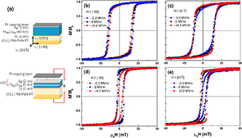
Figure 28. A schematic of (a) a FeCo film and a FeCo/Ag multilayer film on (011) oriented PINMT substrates. Room temperature in-plane magnetic hysteresis loops (b), (c) for FeCo with magnetic field respectively parallel to the [100] and [011] axes of PINMT, and (d), (e) for the FeCo/Ag multilayer with magnetic field respectively parallel to the [100] and [011] directions.
Download figure:
Standard image High-resolution image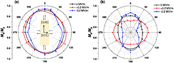
Figure 29. The in-plane angular dependence of the remanent magnetization (normalized to saturation) at zero electric field and 0.2 MV m−1 for (a) a FeCo film and (b) a FeCo/Ag multilayer film. The direction of strain imposed by the substrate along the two in-plane axes is shown in the inset. (From [70]).
Download figure:
Standard image High-resolution imageTo maximize the ME coupling coefficient, the electrically driven phase transformational strain can be exploited. As the converse ME coupling is also directly proportional to the piezomagnetic coefficient (defined as d3m = dλ/dH, where λ is the magnetostriction), it is assumed that achieving near-zero stress conditions while close to the phase transition stress is required to fully couple the transitional strain to the magnetic phase. In the ME heterostructures based on FeCo/PINMT the strategy of strain engineering was attempted to boost the converse ME coupling by tailoring the stress during the magnetic film deposition. This approach was successfully demonstrated by Garten et al [77] using the combination of the strain preset during the growth and during measurements resulting in the value of the converse ME coupling coefficient being increased by ∼3X for the strain-engineered specimen, reaching values of ∼10−5 s m−1, the highest currently reported value for room temperature, non-resonant converse ME coupling (see figure 30).
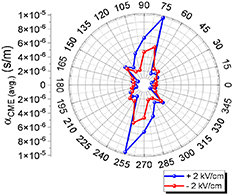
Figure 30. The converse magnetoelectric coupling of an artificial multiferroic heterostructure grown and measured under strain exhibits a maximum αCME coefficient of ∼1 × 10⁻⁵ s m−1. The large CME response occurs due to the combination of strain engineering approaches (from [77]).
Download figure:
Standard image High-resolution imageThe 2R 32 mode transduction modality near the FR − FO transition in domain engineered single crystals has been used to construct a non-resonant ME energy harvester. The hybrid harvester demonstrator is comprised of a highly magnetostrictive Fe81.4Ga18.6 (Galfenol) rod and a ternary domain engineered PINMT single crystal poised near the FR − FO transition by means of mechanical compression. Details of the device architecture and performance under magnetic field oscillations can be found in Finkel et al [78, 79]. Briefly, the figure of merit (FOM) αME of the ME energy conversion may be written as:
where V is the generated voltage and t is the thickness of the piezoelectric phase. The values aME were found to be 1.38, 1.34, and 82.9 V(cm Oe)−1 when the PINMT crystal is in the FR phase, FO phase, and near the FR − FO transition region respectively. This latter value is an order of magnitude larger compared to previous results [65]. Besides variations in magnetic field, the inherent piezoelectric and pyroelectric properties of the domain engineered single crystals make it conceivable to optimize the harvester design to take advantage of ambient variations in mechanical and thermal energies as well (see section 5), thereby making it a multi-modal harvester.
In addition to very high piezoelectric response, these relaxor single crystals also exhibit outstanding optical properties and remarkable electro-optic modulation ability. The growing need for materials that provide dynamic modulation of fundamental physical properties across all energy domains (electrical, magnetic and optical) has become of paramount importance with the advent of quantum communication and data processing, memory storage and logic gates and optical based communications and electronics vital for defense applications. Several archetypical piezoelectrics and FEs have already been shown to have a high potential for electro-optic or photonic applications including wireless energy transmission, optical switches, optical filters, polarization control, and quantum encoding [80–82]. However, most highly piezoelectric materials are relatively opaque due to local polarization scattering as the domain structure within FEs account for the majority of light scattering due to a discontinuous refractive index at each domain boundary. These multiple FE domains and local polarization directions contribute to excessive multiple light scattering events making the crystal opaque, limiting electro-optics, until recently. In principle, completely eliminating domain walls can create a mono-domain crystal with maximum transparency but often at the expense of piezoelectric efficiency. However, recently we demonstrated that in domain-engineered FE crystals the change in the phase is accompanied by rapid switching from poly- to mono-domain states [48] in [011] poled PINMT under a mechanical load as described in previous sections. This switching reduces the refractive index discontinuity at the domain interfaces, thereby significantly reducing the light scattering (see figure 31 below). At certain wavelengths, over 70% change in transmittance was observed when going from the FR to FO phase.

Figure 31. Optical transmittance of a relaxor ferroelectric PINMT single crystal under 40 MPa stress load plotted in red (with picture on top right) and unloaded (pictured on bottom left) plotted in black (from [48]).
Download figure:
Standard image High-resolution imageThe phase switching was also realized dynamically through this phase transition in PINMT with a sinusoidal electric field of frequency 1 Hz and amplitude 1.25 kV cm−1 and increasing stress (see figure 32). The light transmission increased with compressive stress, especially when it exceeded −20 MPa, corresponding with an anomaly in the stress–strain curve that is associated with stress and/or field induced FR − FO phase transitions. These transitions lead to bimodal functionality—variable optical transparency as well as a giant effective piezoelectric effect.
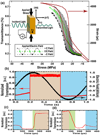
Figure 32. (a) Stress dependence of the integrated transmitted light intensity and strain. The measurements were done with a high‐speed video camera with the sample illuminated with a wide spectrum white LED source while an ac electric field was applied, and the gray and black dots correspond to the maximum and minimum electric fields, respectively. The inset shows a schematic of the setup for the transmittance measurements. (b) Time‐dependent optical relative normalized transmission of 730 nm radiation through the sample along the ![$\left[ {01\bar 1} \right]$](https://content.cld.iop.org/journals/0964-1726/33/1/013001/revision2/smsad06deieqn53.gif) direction measured by a high‐speed photodetector, showing the repeatable and reversible nature of the effect for a crystal under ≈22 MPa compressive stress.
direction measured by a high‐speed photodetector, showing the repeatable and reversible nature of the effect for a crystal under ≈22 MPa compressive stress.
Download figure:
Standard image High-resolution image7. Compact high source level sound projectors
Further advances in development of novel types of high-power acoustic sources for various naval applications demands new materials with exceptional transduction capabilities. Most transduction devices are based on strain produced in a piezoelectric or magnetostrictive material [83]. These materials can produce relatively large strain in a linear region but in order to develop high strain they must be driven by a very high electric or magnetic field that is not always achievable. In conventional low frequency acoustic sources, the acoustic pressure is linearly proportional to the mechanical displacement of a sound generating surface that is directly related to the electrical field applied in the active material. Thus, large displacements require large fields and consequently, large amounts of electrical power.
There are several classes of materials utilizing high strain associated with a martensitic phase transition (namely, shape memory alloys (SMAs) [84]). However, high strain in SMAs is thermally activated and transduction devices based on them have frequency band limitations. Relaxor FE single crystals (for example, lead zinc niobate lead titanate—PZNT, or lead niobate lead titanate PMNT) are highly promising for this application as they have been shown to deliver extraordinarily high strain when an external electric field is applied [85–87] as compared to conventional polycrystalline piezoceramics (e.g. PZT). Recent single crystal transducer development results promise low frequency, high power, more compact devices with significant size and weight reductions. Examples include segmented rings of single crystal bars, bilaminar flexural bar transducers and miniature class V flextensional (cymbal) driven panel projectors [83, 88]. The demonstrated improvements are primarily due to the single crystal's higher piezoelectric drive coefficient ∼1500–2000 pm V−1, high electromechanical coupling coefficient ∼0.9 and lower sound speed—approximately half that of PZT. Maximum strains on the order of 1% [3] have been demonstrated in specific binary compositions of PZNT. Yet a key issue for designing a transducer is the need to provide large electric fields (3 MV m−1) to reach these extraordinary strain values, as well as applying a DC electrical bias field that is typically over half the AC field. In practice such fields are hard to contain and keep separate.
At lower acoustic frequencies, larger displacements are required to generate the longer wavelengths. This creates unsurpassable limitations for transducers as they push and pull greater mass for the same volume displacement and thus are limited in their acoustic output power.
As a result, high power underwater acoustic projectors are very large and heavy. Flexing shell transducers (∼100–500 Hz) on the order of meters in size with weights in the hundreds to thousands of pounds, generate relatively high source levels. To get lower, hydroacoustic sources (∼5–50 Hz) were developed. These operate using a high-pressure fluid that is oscillated through a spooling valve system to drive large metal membranes. Further into the infrasonic region, air guns (∼5 Hz) are impulsive sources that discharge compressed air in an explosive manner to generate repeatable (but non-uniform) intense acoustic pulse spectra for geophysical exploration. In all these cases the devices become larger, heavier, and more complicated as the frequency range of operation goes down.
One way to circumvent the limitations and significantly reduce the electrical power while maintaining the output levels is to utilize the phase transitions in these relaxor crystals. For instance, the isothermal elastic response of domain engineered 4R 33- and 2R 32- modes of morphotropic PZNT single crystals to harmonic stress (∼50 MPa) was investigated by Amin and Cross [6], and Okawara and Amin [89] and they observed a reversible and hysteretic stress–strain response that is characterized by a large and sharp strain discontinuity 
 R–O (∼0.5%) occurring at a critical stress
  that was attributed to the FR − FO transition caused by polarization rotation under mechanical compression. The reversible effect under de-compression is due to charged domain walls [6]. A similar effect was also reported in domain engineered ternary PINMT single crystals as was discussed in previous sections [87]. However, in ternary single crystals (i.e. PINMT) the phase transition between rhombohedral and orthorhombic crystal lattice arrangements exhibits huge strains as well as modulus variations. This phase switching then can provide a method to deliver strain levels of ∼0.5% at relatively low (∼0.1 MV m−1) drive fields as was recently reported [3, 87]. This represents a five-fold strain increase at only 20% of the drive field and without any dc bias, compared to the linear piezoelectric mode in relaxor FE single crystals. Briefly, one can take advantage of the elastic instability that was reported in both binary (PZNT) and ternary (PINMT) domain engineered single crystals for acoustic transduction.
By successfully harnessing this intrinsic material state switching phenomenon, one would obtain SONAR transducer devices with even greater performance than the binary single crystal-based projectors currently under development. This approach introduces a new transduction modality that relies on a spontaneous phase transition rather than continuous strain and polarization change under external stimuli (i.e. field, stress, and temperature). Here, the electric field and stress dependence of the strain exhibited by single crystal FEs is exploited to produce large displacements (up to 4000 microstrain), with relatively low dynamic perturbations obtained via mechanical, or electrical drive. By bringing the crystal close to the critical mechanical bias operating point, the displacement amplitude of the crystal is practically independent of the supplied electrical power. The switching frequency is limited by the period of oscillation between crystallographic states which is known to be faster than 1 µs [48].
To demonstrate this effect, a [011] poled PINMT crystal bar was installed into a transducer assembly (a Tonpilz-type design) driven over a broad range of frequencies. Electrical leads were attached to the electrodes on the surface of the crystal, and the crystal was inserted into the transducer apparatus as shown in the schematic in figure 33. A screw on the top was used to apply an adjustable compressive pre-load to the crystal. The crystal was placed between two ceramic shims, and for optimal boundary conditions there were several spring washers below the head adapter. The sound was transmitted from the cone on the opposite side, which was submerged in water and directed at the hydrophone. The transducer was not potted with oil or otherwise waterproofed and remained above the surface of the water during testing. The performance of the transducer was tested in water and showed up to 15 dBSPL higher acoustic power radiated when the crystal was driven through the phase transition than when operating in the linear piezoelectric regime (figure 34), thus demonstrating the potential of this phase transitional strain for use in acoustic transducers.
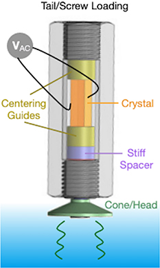
Figure 33. Schematic of transducer used in the SPL in-water measurements, explaining crystal placement and application of mechanical bias (from [90]).
Download figure:
Standard image High-resolution image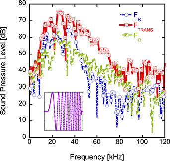
Figure 34. (a) Sound pressure level for three regimes (FR, FTRANS, and FO) in water, normalized to 1 m. The inset shows the formed pulse used for excitation. From [90].
Download figure:
Standard image High-resolution image
8. Conclusion
A transduction modality based on the FE–FE phase transition in domain engineered relaxor-FE single crystals poised near an instability was reviewed. Prototype devices have been developed and demonstrated the vast electromechanical capabilities of this modality. Compact broadband high source level sound projectors using this modality have delivered 10–15 dB more source level over two and half octaves compared to their linear piezoelectric mode counterpart. This has a direct impact on underwater acoustic devices (kHz range) and with engineering development will benefit medical ultrasound devices (MHz range).
Mechanical energy harvesting devices have delivered a harvested energy density per cycle that is two orders of magnitude larger than that of linear piezoelectric bimorphs operating in a resonance mode. Multiferroic ME heterostructures have demonstrated one of the largest ME coupling coefficient reported up to date >2 × 10⁻⁵s m−1 at room temperature. The unprecedented control of optical properties was shown at very low electric fields (<1.5 kV cm−1) accompanied by a giant (>10 000 pm V−1) piezoelectric coefficient that is superior to that of linear state‐of‐the‐art materials by 3X. The coexistence of tunable optical transmissivity and high piezoelectricity paves the way for a new class of photonic devices.
Over the past 15 years, we have accumulated a significant body of knowledge in the fundamental understanding of this transduction modality in different binary and ternary high electromechanical coupling single crystal systems, its device physics, and the behavior of domain engineered FE single crystals under thermal, mechanical, and electrical loading. In conjunction, several issues have emerged, for which we do not have definitive answers. These are discussed next.
The following question may arise: Is it possible to achieve a large strain ∼1% at low drive field using this transduction modality? The phenomenological expressions 2.1 and 2.2, show that the strain associated with inter-FE rhombohedral–tetragonal transition SR–T is twice that associated with rhombohedral–orthorhombic transition SR–O, in agreement with the experimental observations. A one percent strain (associated with the FR − FT transition) was previously reported at large drive fields (a few MV m−1) in the unclamped (mechanically free) domain engineered crystals [6]. A half percent strain (associated with FR − FO transition) was demonstrated at an order of magnitude lower drive field in the mechanically stress biased crystal [36]. Recent grazing incident diffraction results suggest that it is possible to domain engineer crystals that can deliver high strain at low field. One possibility is to select the FR − FT transition path, perhaps in a ternary single crystal composition, and use the transduction modality near the FE–FE instability.
The role of charged domain walls in driving reversible inter FE transitions is evident in the 4R 33- and 2R 32-, 2R 31-modes with 4mm and 2mm macro symmetries respectively. However, this is not the case for the 33-mode geometry with 2mm macro symmetry (2R state) as demonstrated in crystals fabricated from two entirely different ternary systems, i.e. PMNZT and PINMT. In both systems, a uniaxial compression causes the 2R domain state to rotate in the mirror symmetry plane, leading to a stable 180° tail-to-tail tetragonal (2T state). This state is stable under free electric and elastic boundaries. The 2T domains are related by a mirror plane perpendicular to the polarization vector, leading to a nonpolar 4/mmm symmetry. This polar to non-polar transition is irreversible. The charged domain wall role is absent in restoring the 2R polar symmetry for reasons that are not clear at present. The original 2R state can only be restored by re-poling the crystal. X-ray diffraction could be used to detect changes in the lattice translation symmetry associated with the 2R to 2T transition. We hypothesise a doubling of the lattice periodicity along the four-fold symmetry axis, i.e. the tetragonal c-axis of the 2T state. A full structure analysis of the 2T state, using neutron diffraction, (to avoid heavy atom dominance of the scattered x-ray intensities,) will reveal the cation/anion shifts of the corner-linked oxygen octahedra, that are responsible for polarization vector development in the 2T state. Computation of the three-dimensional electron density in the crystal, using the atomic coordinates as determined from neutron diffraction, may provide valuable insights on this phenomenon.
Ferroelastoelectricity in domain engineered single crystals with macro symmetry 2mm was theoretically demonstrated based on symmetry and energy argument [29, 31]. All the symmetry allowed modes for [111]C and [ 11]C state shifts under the combined application of mechanical stress and electric field were enumerated and the driving potential for state shifts was developed [32]. One of the allowed modes involves the simultaneous application of a colinear uniaxial compression
  , and electric field E2 along the X2- axis of the domain engineered crystal. Experimental verification of this phenomenon via diffraction and or optical methods, will provide deeper insights into the domain dynamics of these complex systems.
Development of etching methods for nondestructive removal of the surface layer is desirable. The effect of surface layer on physical properties will be more pronounced as the crystal gets thinner, e.g. in optical, high frequency ultrasound imaging, and receive-mode devices. This problem has been encountered during the development of densely populated two-dimensional pyroelectric imaging arrays fabricated from polished FE barium strontium titanate thin wafers. Etching methods were developed for surface layer removal. This resulted, among other things in a vast improvement of the imaging system FOM [91], the NETD.
Transitioning of concepts and devices developed in this work to the wider application arena remains a substantial challenge. Application specific issues such as hysteresis, heat generation, fatigue, and cycle ageing are still open for investigation.
Acknowledgments
We thank the Office of Naval Research, and the program manager Dr Wallace Smith for his insights, criticism, and support. We also thank Dr Lynn Ewart of the Naval Undersea Warfare Center (NUWC) for establishing the Transduction Materials and Devices group. This work would not have been possible without their support. We thank Dr Margo Staruch of the Naval Research Laboratory for critically reading the manuscript and compiling the references.
No reader of this work can fail to recognize how much we owe to others who have contributed to this field, to the authors of the work quoted in the bibliography, and to those whom we have failed to mention, we express our sincere thanks.
Data availability statement
All data that support the findings of this study are included within the article (and any supplementary files).