
Abstract
This study presents the design and development of a 2D auxetic filtering medium with programmable geometric features specifically designed to vary under in-plane tensile strain. This feature empowers the filtering medium to control the particles separation. A novel design and optimisation algorithm developed in Matlab® determines the final optimized geometry of the filtering medium based on the desired particle size input. Upon thorough numerical investigation, an empirical relationship between the linear elastic in-plane tensile strain and aperture size of the proposed metamaterial is revealed. This empirical relation can be used in mechatronic and control systems to steer the proposed filtering medium. A prototype of such filtering medium capable of classification of particles of size 4 mm to 4.5 mm, when subjected to linear strain, is fabricated through fused deposition modelling process. The developed geometry configurations in this research are scalable, providing a potential cost-effective and efficient solution for industrial applications including reconfigurable filtration and segregation systems.
Export citation and abstract BibTeX RIS

Original content from this work may be used under the terms of the Creative Commons Attribution 4.0 license. Any further distribution of this work must maintain attribution to the author(s) and the title of the work, journal citation and DOI.
1. Introduction
There has been a growing interest in modern industries in the intelligent design of materials and structures with properties and functionalities that may not be achievable by conventional material design. Mechanical metamaterials are man-made materials, the properties of which depend predominantly on their geometrical construction. This advantage allows designers to acquire tailored physical and mechanical properties. Metamaterials exhibit exceptional properties, and recent advancements in additive manufacturing (AM) have enabled their use in applications that are unachievable with conventional or naturally occurring materials [1]. Metamaterials are made of an elementary geometry called a unit cell. A unit cell holds and defines all the characteristics and functionalities of the metamaterial when combined and arranged in a repetitive order in a spatial space. This arrangement of unit cells is called a lattice structure [2–4]. Metamaterial properties primarily depend upon the geometry of the unit cell rather than only relying on the building material from which it is fabricated from [2, 5]. A unique design of a unit cell for a metamaterial allows for achieving unique physical properties like an unfeelability cloak [6] and optical properties like a negative refractive index [7].
Poisson's ratio (υ) is a property of a material that indicates the negative of the ratio of transverse strain to axial strain) [8]. It is a unitless number that is commonly positive (usually ranging from 0.25 to 0.5) for naturally occurring materials or 'non-auxetics' (figure 1(a)). Conversely, materials with auxetic properties exhibit a contrary response, whereby they shrink when subjected to compression and expand when pulled by tension, owing to their negative Poisson's ratio (NPR) behaviour (figure 1(b)). Auxetic behaviour has also been observed in several natural and biological materials [9]. Similarly, several studies have presented the development of zero Poisson's ratio (ZPR) metamaterials for various applications, such as shape recovery and energy absorption [10–12].

Figure 1. The schematic of material's response under a tensile load; (a) positive Poisson's ratio and (b) negative Poisson's ratio.
Download figure:
Standard image High-resolution imageIn addition to auxetic behaviour, there are many other artificial mechanical behaviours like negative stiffness, negative compressibility, and ultra-lightweight ultra-high stiffness properties that are achievable through different types of mechanical metamaterials [10, 13]. Such properties are controllable by tuning the unit-cell geometry through several methods like computer-aided design (CAD) and topology optimisation [12, 14, 15]
Due to this unique behaviour, auxetics have been considered for different applications such as prosthetics [16], tissue engineering [17], sports practice [18], textile industry [19], biomechanical [20], vibration isolation [21] and enhanced thermo-mechanical applications [22]. Silva et al [23] presented a comprehensive review on the chemical composition, and physical and mechanical properties of the cork material and signified its products and sub-products. Cork is a naturally occurring material made of suberin polymer microstructure usually used as a glass bottle cap. This material has a ZPR. Therefore, opening and sealing a glass bottle does not produce lateral pressure on the bottleneck due to compressive and tensile forces. This behaviour is essential in order to prevent breaking the glass bottle's neck [23]. Luo et al [24] studied the properties of auxetic tubular structures which showed decent performance for impact, bending loads, synclastic and conformability around curved objects. Ren et al [25] designed and developed auxetic nails which are easy to penetrate and hard to remove.
The recent progress in design, modelling, and manufacturing has enabled the creation of new auxetic structures for different modern applications. With the help of advanced CAD software, various types of cellular structures can be modelled with different Poisson's ratios from negative to positive. Auxetics are designed in various shapes in order to obtain desired NPR value in conjunction with other mechanical properties like stiffness, elasticity and modulus of resilience to name a few [26]. Auxetics are designed through mathematical representation of the unit cell geometry and evaluating the effect of design variables on the mechanical properties like elastic modulus E, bulk modulus K and shear modulus G [27]. Auxetics are also designed using topology optimisation techniques [25, 28–30].
Auxetic structures are modelled and fabricated in two general configurations, 2D thin sheet auxetics [31–33] and 3D auxetic lattice structures [28, 34]. Elipe et al [35] presented a comprehensive study of 2D and 3D auxetic structures and compared the auxetic properties of different designs. Auxetic structures can be designed to exhibit either isotropic or anisotropic properties. For example, an isotropic auxetic design shows an NPR behaviour that equally expands the metamaterial in two lateral directions (x-axis and y-axis equal) when a tensile force is applied along the z-axis and vice versa [36]. In contrast, anisotropic auxetics behave differently when the load is applied in different orientations. Research in isotropic auxetic structures has shown the importance of different designs and their associated applications in 2D [37] and 3D [28]. With respect to functionality and applications, anisotropic auxetic metamaterials can also be designed to obtain desired mechanical responses, for instance, 2D anisotropic auxetics were used in mechanical actuators and soft robotics [38]. Similarly, 3D anisotropic auxetics are discussed and presented in different research [39].
In recent literature, there has been a growing interest in the design and fabrication of tuneable auxetic metamaterials to achieve a range of desirable mechanical properties such as impact resistance and conformability around complex shapes. 2D auxetic metamaterials have been designed in different shapes and types such as strut-based structures, extruded patterns, topology-optimized cells, cutting shapes of slits, triangular cuts, chiral, honeycomb and re-entrant [26]. Depending upon the building material and geometrical complexity of the design, a suitable manufacturing process is employed for the fabrication of the auxetic structure. For instance, AM processes such as fused deposition modelling (FDM) [26] and stereolithography (SLA) are commonly used for the fabrication of strut-based and extruded-based auxetic designs. CNC laser-cutting has been utilized for the fabrication of designs which involved slits and cutting geometries [40].
2D auxetic metamaterials have gained significant interest in the mechanical metamaterial design research community. Rezaei et al [32] developed 2D auxetic metamaterials with hyper-elastic properties using a density-based topology optimisation technique. They observed the deformation mechanism and characteristics of the auxetic metamaterial that were highly dependent upon the topology optimisation variables. Wang et al [33] designed and developed a thin metamaterial film with excellent conformability and adhesion for bandage substrates in order to achieve a non-uniform Poisson's ratio that mimics a functionality similar to human skin.
In several engineering applications, filtration is a common approach for separating particles into different size classes for further physical, chemical, or biological analysis. Conventional filters are designed to capture particles within a specific size range. Developing a smart filtering medium that can effectively work for particles of varying sizes, is a challenging task for the industry. Alderson et al [41, 42] are among earliest researchers who discussed the potential use of 2D auxetics as a filtering medium. Because the auxetic metamaterial's property depends upon the construction of its unit cell geometry, by scaling the unit cell up and down between the centimetre and nanometre range [43, 44] the associated filtering property can be scaled proportionally. Mizzi et al [45] studied a nano-scale 2D in-plane auxetic metamaterial and established a relationship (equation (1)) to demonstrate how the porosity and aperture shape of the auxetic metamaterial change proportionally upon the applied strain (figure 2). The aperture size of the metamaterial is controlled by its geometrical design variables and an applied strain as presented in equation (1).
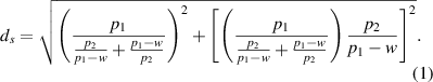
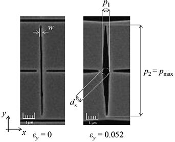
Figure 2. Demonstration of the auxetic cell proposed for particle filtering by Mizzi et al. Reprinted from [45], Copyright (2020), with permission from Elsevier.
Download figure:
Standard image High-resolution imageIn equation (1),  represents the size of the passable spherical body,
  is a pore parameter indicating the maximum size of a passable spherical body,
  is the initial width of the slit, and
  is the length of the rhombic pore. Their results showed that the porosity was doubled by applying up to 5% strain, allowing a significant increase in the maximum permissible size of the particles passing through the filter.
The potential applications of programmable filtering media can be found in various industrial settings where precise particle separation and filtration is needed. This can involve water filtration, air filtration, chemical and gas filtration, biomedical applications, and the processing of food and beverages. The use of 2D auxetic materials as a filtering medium has not yet been fully investigated in the research community. In this study, the applicability of a 2D auxetic metamaterial for the construction of a smart filtering device is investigated. In contrast to the previous research [45] which only studied the feasibility of such an application, this study presents a novel design of a 2D auxetic structure with a comprehensive solution as a filtering device followed by prototype construction and experimentation. Since the geometrical features of the auxetic cellular structure play an important role in the functionality of the structure as a filtering medium, an optimization approach based on Genetic algorithm (GA) is proposed and utilised in this study to enable finding the best design for filtration and classification of desired-sized particles. The design is tuned to enable controlled filtration of different-sized particles through an applied strain within a linear elastic region.
2. Methodology
The applied methodology is presented through the following four sections:
- Design strategy for the proposed auxetic filter
- Optimization of the design through a GA
- Finite element analysis (FEA) of the designed auxetic filter
- Prototyping and mechanical assembly
2.1. Design strategy for the proposed auxetic filter
The novel design of the 2D auxetic unit cell is developed with the help of a set of mathematical equations. This mathematical model is based on parametric equations of torus geometry which were initially developed in Desmos browser-based graphing calculator (Desmos Studio) as demonstrated in figure 3(a). The corresponding CAD model was then developed in Matlab® as shown in figure 3(b).
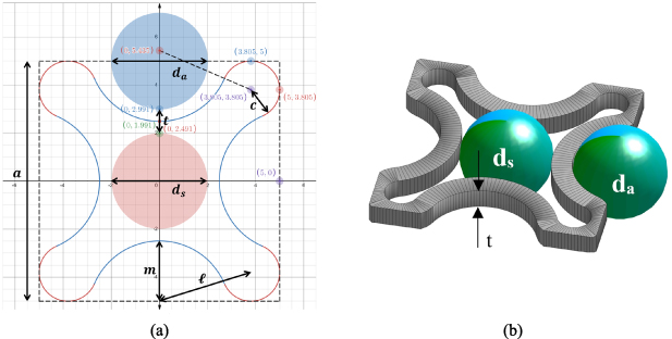
Figure 3. Schematic of the proposed unit cell design for particle filtering developed in Desmos (a) and the corresponding 3D CAD model developed in Matlab (b).
Download figure:
Standard image High-resolution imageEquations (2)–(4) present the relationship between the different geometric design variables as shown in figure 3(a):

where  is the size of the aperture at the cell centre and
  is the size of the aperture on the edges of the cell, as demonstrated in figure 3. t represents the strut width/thickness, c is the radius of corner arcs, ℓ is the centre-to-centre distance from corner arc c to edge arc m,
  is the constant for the parametric arc, and m represents the radius of the edge arcs. In order to achieve a valid geometry,
  can vary from 0.12 to 0.19, and
  can vary from 0.45 to 0.7. The cell centre aperture size to cell size ratio
  varies from 0.27 up to 0.69 and the edge centre aperture size to cell size ratio
  varies from 0.11 to 0.46.
  is the main aperture calculated from the equation (4) and the selection of c and l is only valid for the values which will result in
  . These parameter domains were calculated from equations (2)–(4) under no load condition that means no strain was applied to the filtering medium. These are presented in dimensionless format since the relationship between the geometrical design variables and particle filtering is scalable.
2.2. The optimization of the design through GA
A GA developed in Matlab® is utilized to find the best geometry parameters for filtering the desired particle size. GAs mimicthe natural selection and evolutionary process to improve certain features following a number of generations [46]. GAs have been utilised in structural optimization and design for AM in previous research [47]. To implement GA in this study, the number of generations was set to 50, population size was set to 20, the number of pairs of chromosomes to cross over in each generation was four and the number of chromosomes to be mutated in each generation was four. A population of potential designs were initially generated based on random allocation of  and
and  (the two design variables) values within the valid range defined in section 2.1. Each design was represented by a chromosome of 40 bits in length, with 20 bits allocated for each design variable, providing an accuracy of up to five decimal points. The design chromosomes cross over and mutate during each evolutionary iteration to generate new design possibilities. The fittest designs which will proceed to the next generation will be those with lowest values of objective (cost) function. The objective function
  is defined as the difference between the aperture size of the filtering medium and the size of the particle to be filtered, i.e. the optimization program seeks to minimize the gap between the particle and the boundary of the aperture:

where  denotes the particle size. The objective function is evaluated in each evolutionary iteration for the whole population of designs to find the best values of design variables c and ℓ and the corresponding geometry. Convergence is achieved when the generation of new designs does not result in a geometry different to the previous generation.
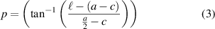
A sample run of the GA program with the above GA parameters was tested to optimise an auxetic structure of cell size 10 mm for filtration of particles of size 4 mm, i.e. the particle size to cell size ratio ( ) of 0.4. Figure 4 presents the evolution history and convergence of the objective function. It can be seen that the first generation of potential designs had an average objective of about 0.075 (corresponding to an average size difference of 0.75 mm between the particle and the aperture), while the best design in that generation had an objective of nearly 0.025 (corresponding to 0.25 mm size difference between the particle and the aperture). Both the average objective and the best objective decreased through the iterative evolutionary optimization process and converged to zero within 40 generations.
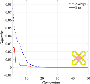
Figure 4. Evolution history of objective (cost) function.
Download figure:
Standard image High-resolution image2.3. Finite element analysis of the designed auxetic filter
The proposed filtering medium is capable of controlled filtration of particles of different sizes when the medium is under mechanical strain. To calculate the relationship between the aperture size and the strain, a finite element (FE) model of the 2D auxetic structure is developed with the help of the PDE (Partial Differential Equation) toolbox in Matlab®. In the corresponding FE model, boundary conditions of fixed support on one end and deformation on the other end were applied. A tetrahedral mesh was used to generate the FE model of the structure as shown in figure 5. The max element size of the mesh was  and the min element size of the mesh was
  , where
  is the strut thickness as demonstrated in figure 3.

Figure 5. Demonstration of the mesh used for the FE model of filtering medium with a min element size of  and max element size of
  .
.
Download figure:
Standard image High-resolution imageTo investigate the dependency of the results on the utilised FE mesh, a mesh sensitivity analysis was performed as shown in figure 6. For simplicity, a structure of a  unit cell array was used. The aperture sizes
  and
and  were measured and plotted against element size when the structure was under
  linear strain. As shown in figure 6, the mesh size does not have a considerable effect on the measured values of aperture sizes and
  . The verification of FE model through experimentation is presented in section 2.4.
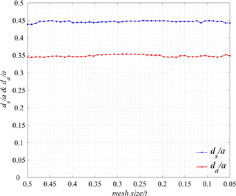
Figure 6. Mesh sensitivity analysis investigating the effect of mesh size on measured values of aperture sizes  and
and  when the filtering medium is under 5% strain.
Download figure:
Standard image High-resolution imageTo study the effect of applied strain on the variation of aperture size, the design was initially optimised through the approach presented in section 2.2 for the filtration of particles of size  . In this case, the optimised design parameters were obtained as
  and
and
 . Figure 7 presents the relationship between
  ,
,  and the applied strain. The results show that by increasing the applied strain, the cell centre aperture size
  increases linearly. Conversely, increasing the applied strain results in reduction of the edge centre aperture size
  . This is due to the curved shape of the auxetic cell struts shown in figure 3(b). When the auxetic structure is stretched under applied tensile strain, the curved strut members tend to become straight. As the cell centre apertures are located on the convex side of the curved struts and the edge centre apertures on the concave side, stretching the auxetic structure results in increasing
  and reducing
  . The proposed auxetic filter is designed primarily to deform under tensile strain however, numerical results corresponding to the compression of the filter is also provided in figure 7 for observation of the behaviour of the filter under compressive strain.
Figure 7. The change in aperture sizes ( and
and  ) under the applied linear strain.
Download figure:
Standard image High-resolution imageFigure 8 shows the transverse (x-axis) displacement contour corresponding to the FE model presented in figure 5, when one end of the structure is fixed and the other end is subjected to an applied displacement of 0.15a, equivalent to longitudinal strain of  . This resulted in lateral expansion of 0.012a on each side of the structure, equivalent to a transverse strain of
  . The Poisson's ratio for the auxetic structure is calculated as
  .
.
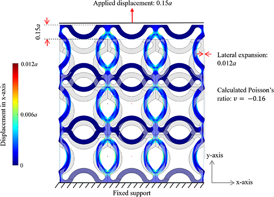
Figure 8. Transverse (x-axis) displacement contour for the auxetic structure under displacement loading.
Download figure:
Standard image High-resolution image2.4. Prototyping and mechanical assembly
The program developed in this study constructs a parametric model of the 2D auxetic structure, optimizes the geometry with respect to desired particle size for filteration, and then exports that optimized geometry into STL file format which can further be used for the fabrication of the filter through an AM process. A prototype model of the proposed filtering medium was 3D printed through FDM process using Prusa i3 MK3 machine (figure 9). The design parameters and global dimensions of the prototype are presented in table 1. The device consists of a frame, a slider and the proposed 2D auxetic structure which is constructed from 11 × 7 auxetic unit cells printed from Flexfill TPU 98 A [48] with mechanical properties presented in table 2. The frame and the slider are printed from standard PLA material [49]. A 0.4 mm nozzle and standard 3D printer settings were used for the fabrication of this prototype through FDM.
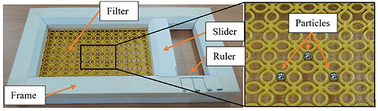
Figure 9. The assembled prototype of the proposed programmable filtering medium.
Download figure:
Standard image High-resolution imageTable 1. Dimensions and design parameters of the prototyped auxetic filter.
| Parameter name | Symbol | |
|---|---|---|
| Global length | L | 110 mm |
| Global width | W | 70 mm |
| Cell size |

| 10 mm |
| Strut thickness |

| 1 mm |
| Design variable-1 |

| 1.19 mm |
| Design variable-2 |

| 5.43 mm |
| Aperture-1 diameter |

| 4.0 mm |
| Aperture-2 diameter |

| 4.0 mm |
Table 2. Mechanical properties of Flexfill TPU 98 A used for fabrication of the auxetic filter [48].
| Parameter | Value | Test method | Test condition |
|---|---|---|---|
| Material density | 1.23 g cm−3 | ISO 1183-1 | |
| Tensile strength | 53.7 MPa | DIN53504 | At the break, 200 mm min−1 |
| Tensile stress | 12.1 MPa | DIN53504 | 10% elongation 200 mm min−1 |
| 22.1 MPa | 50% elongation 200 mm min−1 | ||
| 28.4 MPa | 100% elongation 200 mm min−1 | ||
| 37.8 MPa | 300% elongation 200 mm min−1 | ||
| Elongation at break | 318% | DIN53504 | 200 mm min−1 |
| Hardness | 98 Shore A | ISO 7619-1 | |
| 60 Shore D | |||
| Tear strength | 170 kN m−1 | ISO 34-1 | 500 mm min−1 |
| Abrasion | 23 mm3 | ISO 4649 | Method A |
The slider can move inside the frame to apply deformation to one end of the auxetic filter while the other end is secured to the frame. The two sides of the filter which are alongside the length of the frame can move freely within the provisions provided in the frame. A small millimetre ruler is printed on the frame to check the applied displacement through the slider. As presented in section 2.3, the proposed filtering medium has a Poisson's ratio of  at the current optimized configuration. A small (close to zero) value of Poisson's ratio is advantageous for such application to minimize the lateral deformation of the medium when subjected to deformation, preventing friction, buckling, and out-of-plane deformations. Investigation of these effects is not within the scope of this study.
The feasibility of the proposed device was investigated by distributing different-sized particles (bearing balls of size 4 mm and 4.5 mm), larger than the unstretched filter apertures, on top of the filter and applying a tensile strain by gradually moving the slider. It was observed that by increasing the tensile strain, the aperture size of the filtering medium increased allowing the balls to pass through the filter, thus providing a proof of concept for the proposed programmable particle filtering medium.
In order to confirm the correlation between the strain applied and the size of the filter aperture, an experiment was conducted where a caliper was attached to the slider to measure the minimum displacement required for each particle to pass through the filter. The corresponding applied strains were calculated from the slider displacement. The aperture size of the stretched filter corresponding to the applied strain was calculated through FEA (see figure 7) and compared with the size of the particle which passed through. The experiment procedure is demonstrated in figure 10 and the results are presented in table 3. Figure 10(a) shows the unstretched filter with the apertures designed to be 4 mm in size. However, it can be seen that the 4 mm bearing ball (3.97 mm measured by caliper) is unable to pass through the unstretched filter. This can be attributed to design-to-build discrepancies of 3D printed parts, which is demonstrated in the figure in blue and yellow colours. In this case, the 3D printed filter was slightly tapered from the base layer and up to the top layer. Additionally, the designed filter apertures need to have some clearance in order for the particles of the same size to pass through. As can be seen from table 3, when the applied strain increased to 0.9%, the 4 mm ball could pass through the filter aperture. At this level of strain, the aperture size is estimated to be 4.06 mm through the FEA. When the experiment was repeated for the 4.5 mm bearing ball, the applied strain increased to 5.9% to enable the particle to pass through the filter. The FEA approximates the aperture size at this strain level to be 4.51 mm which is very close to the particle size 4.49 mm. Overall, the results from this observation suggest that the experimental and FEA measurements corresponding to filter aperture size and applied train are comparable and the relation can be calibrated by addressing the 3D printing resolution and accuracy.

Figure 10. (a) Demonstration of unstretched filter and comparison between the original design (presented in blue colour) and the 3D printed model (presented in yellow colour), (b) measuring the displacement required to allow particles to pass through the filter.
Download figure:
Standard image High-resolution image
Table 3. Comparison of the applied strain required for passing two different sized particles through the filter and the corresponding filter aperture size calculated through FEA.
| Case-1: 4 mm bearing ball | Case-2: 4.5 mm bearing ball | |
|---|---|---|
| Exact particle size measured by caliper | 3.97 mm | 4.49 mm |
| Minimum applied displacement to let the particle pass through the filter | 1.02 mm | 6.48 mm |
| Applied strain corresponding to the above displacement | 0.9% | 5.9% |
| Designed aperture size-unstretched filter | 4 mm | 4 mm |
| Aperture size- stretched filter under the applied strain (calculated using FEA) | 4.06 mm | 4.51 mm |
3. Summary and conclusion
To summarize this research, a programmable filtering medium was designed for the first time based on the concept of auxetic metamaterials. In the first stage of the design process, the parametric model of a novel auxetic unit cell was developed and its design parameters corresponding to the filtration of a specific particle size were optimised through GA. It was observed that for the proposed unit cell design, the achievable aperture size ranges from 10% to 50% of the cell size. In the second stage, the relation between the applied linear elastic strain and the aperture size of the filtering medium was established with the help of FE simulations. FE simulations showed that with the proposed design, up to 12% increase in the aperture size can be achieved when the auxetic filter is subjected to 5% linear elastic strain. Lastly, a 3D-printed prototype of the proposed filtering medium was developed with the help of FDM process demonstrating the proof of concept when the prototype was used for the filtration of different-sized particles (bearing balls).
This research stands on the assumption of the linear response of the proposed auxetic metamaterial. Geometric non-linearities response in large deformation and comprehensive experimental validation and calibration is beyond the scope of this research and will be addressed in the forthcoming research work. An important characteristic of the proposed design is scalability which makes the system capable of particle filtering from nano-scale to micro-scale and macro-scale. This property makes the system a potential candidate for implementation as a reconfigurable filtration device in a wide range of applications.
Data availability statement
No new data were created or analysed in this study.
Funding
This study was funded by the Faculty of Computing, Engineering and Media at De Montfort University.
Conflict of interest
On behalf of all authors, the corresponding author states that there is no conflict of interest.