
Abstract
Magnetorheological (MR) fluid dampers (MRFDs) with variable stiffness and variable damping capability (VSVD-MRFDs) have demonstrated excellent vibration mitigation performance. However, there are limited studies on the development of bypass VSVD-MRFDs which offer both higher dynamic range and output force, apart from simple maintenance and straightforward assembly. In this study, a novel large-capacity VSVD-MRFD with an annular-radial bypass MR valve, as opposed to the typical practice of implementing the valve within the traveling piston in the hydraulic cylinder of the MRFD, is proposed. The main contribution of the present work includes: (a) providing the conceptional design and experimental dynamic characterization of the proposed VSVD-MRFD; (b) investigating the feasibility of the proposed damper for realizing the VSVD characteristics under wide ranges of loading conditions. A test rig was, thus, designed to perform experimental characterization of the proposed VSVD-MRFD under wide ranges of mechanical loading and magnetic field conditions. A qualitative analysis including force-displacement, and force-velocity characteristics, together with a quantitative analysis including dynamic range, equivalent viscous and stiffness coefficients, were conducted as a function of loading frequency, displacement amplitude, and applied current. Results showed a maximum dynamic range and maximum output force of 4.5 and 7.8 kN, respectively. Also, the maximum relative increase in the equivalent viscous and stiffness coefficients were obtained, respectively, as 425% and 488%, when the applied current is increased from zero to 2 A. The results confirm the potential of the proposed VSVD-MRFD for applications in off-road suspension systems. The externally designed bypass MR valve permits a straightforward design modification for realizing wide scalability of damping force in different applications (e.g., off-road vehicle suspension systems).
Export citation and abstract BibTeX RIS

Original content from this work may be used under the terms of the Creative Commons Attribution 4.0 license. Any further distribution of this work must maintain attribution to the author(s) and the title of the work, journal citation and DOI.
1. Introduction
Vibration in ground vehicles can cause discomfort and adverse health effect to passengers or operators and even premature fatigue failure of the vehicle aggregates [1]. The primary vehicle suspension system plays a vital role in the mitigation of the unwanted vibration as well as in providing ride comfort and handling stability for vehicles. Currently, suspension systems are categorized as passive, active, and semi-active systems. Passive systems have been widely used in vehicle suspension systems due to their reliability and cost-effective features, however, they have shown performance limitations under varied operating conditions [2]. Active suspension systems can provide remarkable vibration suppression as compared with passive systems by providing controllable actuation force to mitigate vibration in a broad range of excitation frequencies. However, the practical implementation of active systems has been generally hindered mainly due to the complex control hardware and large power requirement to generate the required control forces [2]. Alternatively, semi-active suspension systems with variable damping (VD)/stiffness characteristics can provide the reliability of passive systems while maintaining the adjustability of active systems to a large extent. Magnetorheological (MR) fluid dampers (MRFDs) have been widely employed to realize semi-active suspension systems [3–5]. This is in part due to their fail-safe feature, low-power requirement, fast-response (in milliseconds) and large damping force adaptability without requiring complex control systems [6–9]. The semi-active systems with controllable damping capability have markedly shown great potential in improving the ride comfort, handling and stability of ground vehicles [10, 11]. Semi-active systems utilizing MRFDs have also been implemented in various applications including suspension systems of many luxury cars [12, 13], motorcycles [14], military vehicles [15–17], helicopters [18], ambulances [19, 20] and railways [21], vehicles seat suspension [22, 23], civil buildings and bridges cushions [24, 25] medical applications such as robot leg [26], dental implant surgery and robotic surgery [27], washing machines [28], aircraft landing gears [29], and gun recoil systems [30].
Vibration suppression through the utilization of semi-active devices has mainly been realized via damping variability [31]. Damping variability is mainly effective to reduce the vibration amplitude, particularly at the resonance frequency. In contrast, variation in the stiffness allows adaptively to vary the natural frequency of the system in such a way that can efficiently reduce the transmitted vibration over a broad range of frequencies [32–34]. In particular, the concept of variable stiffness (VS) [35], allows the development of advanced VS semi-active devices, such as vibration isolators [36], which have shown great potential for vibration suppression purposes [37]. Furthermore, the variability of stiffness permits to overcome the conflict between the ride comfort and good handling stability of vehicle suspension design. Since good ride comfort requires soft stiffness while good handling and vehicle stability requires the suspension system to be stiffer [38–40].
To further improve the vibration mitigation performance of semi-active devices, the concept of VS and VD (VSVD) has been introduced and investigated in many proof-of-concepts studies [41–45]. In recent years, VSVD MR fluid dampers (VSVD-MRFDs) have particularly, received growing interest as they have shown better performance to control vibration in a broad range of frequencies compared with traditional MRFDs with only damping variability. Different configurations have been employed for realizing the VSVD-MRFDs. VSVD-MRFDs are realized by establishing a series/parallel connection between damping elements and stiffness elements. The stiffness element can be classified into mechanical and pneumatic elements. Generally, two MR valve (MRV) units are utilized to achieve stiffness and damping variability. One MRV unit provides damping variability, while the other MRV unit controls the stiffness variability.
The earliest studies on VSVD-MRFD mechanical systems trace back to 2005 when Liu et al [46] proposed a VSVD system in which two MRFD units assembled in series, thereby leading to dependent control of VS and VD units. They subsequently designed a VSVD which offers independent control of VS and VD units, although under a limited stroke of 10 mm [47]. Sun et al [34] designed a VSVD device consisting of two MRV units along with one single spring element. On the basis of the developed VSVD device, Sun et al [39] later designed a quarter-car test rig to evaluate the performance of a VSVD-based suspension system. Their results showed a significant reduction in the sprung mass acceleration of the quarter car suspension system integrated with the VSVD thus improving the ride comfort as compared with the passive and VD suspension systems. They further developed a more compact VSVD device including two MRV units and two spring elements, which permitted dual and individual controllability of stiffness and damping [48]. The equivalent stiffness of the system was varied between two modes by adjusting the applied current to the outer damping cylinder while changing the equivalent damping was achieved through the application of the current to the inner damping cylinder. It was shown that the damping coefficient can vary from 16.24 to 29.72 kN s m−1 by adjusting the current of the inner damping cylinder from 0 to 2 A, while the equivalent stiffness was also varied from 8.7 to 24.5 kN m−1 by controlling the current to the outer damping cylinder from 0 to 1 A. Moreover, the results stated that the loading frequency has a negligible effect on the equivalent stiffness and damping. Deng et al [49] designed a VSVD-MRFD with independent control of stiffness and damping units. They presented a theoretical model considering three stages for the VSVD-MRFD due to the friction and the yield of MR fluid. Their simulations showed that these stages can be controlled by applying current to the different chambers yielding variation of the equivalent stiffness of the device. It was also found that the VS capability of the device is significantly related to two spring stiffness ratios and currents applied to the outer MR chamber. Deng et al [50] subsequently employed the designed VSVD-MRFD to develop a new VSVD semi-active seat suspension, thereby improving the ride comfort of an off-road military vehicle subjected to harsh operation excitations with low frequencies and large amplitudes. The results showed relative increments of 186% and 520% in the equivalent stiffness and damping, respectively, which subsequently yielded a substantial decrement of 22.1% in the seat suspension's root mean squared acceleration response. Greiner-Petter et al [51] proposed, analyzed and tested a simple VSVD system consisting of three fluid chambers (one input and two output chambers). The two output chambers are connected to the input chamber using two MRVs that were also connected to two springs (with different stiffness coefficients) through two pistons. However, the system stiffness could only be varied among three discrete values, depending on the state of the two MRVs (open/close); besides it has a limited damping force and stroke. Lian et al [52] also designed a VSVD-MRFD with two MRVs and two elastic elements for realizing the VS capability. However, the variation of stiffness modulation with respect to applied current was not presented in their analysis and the maximum force was only limited to 0.06 kN. While the damping and stiffness can be varied independently in the above-mentioned devices, they generally have a complex design, bulky shape, high cost and limited stroke to be implemented in a vehicles suspension system. Zhu et al [33] developed a compact long-stroke VSVD-MRFD with self-powered generation capability. The equivalent stiffness of the VSVD-MRFD can vary between three modes corresponding to the applied current. The proposed damper was tested experimentally under a harmonic motion of 0.15 Hz and 30 mm displacement. The testing results revealed that the effective stiffness can increase from 17.6 to 25.93 kN m−1 by varying the applied current from 0 to 2 A, while the equivalent damping coefficients varied from 11.78 to 18.68 kN m−1 s1, correspondingly. Harris et al [53] designed a VS MR fluid rubber joint to address the trade-off between low and high stiffness of the primary longitudinal suspension for railway vehicles, associated with enhanced curving performance and high-speed stability, respectively. While the VSVD device showed an increase of 88% in stiffness ranging from 370 to 690 kN m−1, it was quite heavy and bulky, and its stroke was limited to 4 mm. Besides, the output force of the VSVD device was limited to 1.5 kN. VS modulus was also investigated under limited ranges of loading conditions. A summary of studies reporting experimental characterization of VSVD-MRFDs has been provided in table 1. As it can be realized, the VS modulus has been investigated under limited ranges of loading conditions.
Table 1. Summary of studies reporting experimental characterization of VSVD-MRFDs.
| Lead author, year | Max. force (kN) | Damping range (kNs m−1) | Stiffness range (kN m−1) | Loading conditions | Stroke (mm) | |
|---|---|---|---|---|---|---|
| Frequency (Hz) | Amplitude (mm) | |||||
| Liu et al [44], 2005 | 0.03 | 10.83 Ns/m | 1.572–3.12 | 4 | 10 | — |
| Liu et al [47], 2008 | — | 0.044–0.163 | 1.64–4.67 | 1.99–3.35 | 5 | — |
| Li et al [54], 2009 | 0.012 37 | — | 5–25 | 0.5 | 0.5 | — |
| Greiner Petter et al [51], 2014 | 0.028 | — | 1.67, 3.54 and 14.433 | 1 | 17 | — |
| Sun et al [34], 2015 | 0.17 | 21.55–51.21 | 11.3–30.5 | 0.1 | 10 | — |
| Sun et al [48], 2015 | 0.6 | 16.24–29.72 | 8.7–24.5 | 0.1–2 | 10 | 71 |
| Jugulkar et al [55], 2016 | — | 0.456–7.34 | 43 500–53 800 | 1–8 | 70 | — |
| Deng et al [49], 2017 | 0.2 | — | 11.9–20 | 0.1 | 13 | — |
| Harris et al [53], 2017 | 1 | 22.99–37.05 | 370–690 | 1 | 2 | — |
| Sun et al [39], 2019 | 0.9 | 5.8–17.85 | 25.4–45.2 | 0.5–2 | 14 | — |
| Deng et al [50], 2019 | 0.25 | — | 5.6–10.4 | 0.1 | 15 | |
| Zhu et al [33], 2019 | 2 | 11.78–18.68 | 17.6–25.93 | 0.15 | 30 | 105 |
| Huang et al [41], 2019 | 0.2 | 4.9–8.4 | 13.8–35.8 | 0.5–2 | 5 | — |
| Lian et al [52], 2022 | 0.06 | — | — | 0.01 | 5 | — |
VSVD concept may also be achieved through connecting a pneumatic spring with MRVs. Youn and Hac´ [56] proposed a VSVD suspension system utilizing air springs. The system stiffness varied between three definite values. Based on the vehicle system's performance, a semi-active system with VD and fixed stiffness is recommended. Li et al [54] designed a VSVD-MRFD consisting of an MRV, air spring, and accumulator. The stiffness variability was realized by varying the MRV damping. Zhang et al [57] presented a VSVD device including one MRV unit, an air spring, and two separate films. Stiffness variability was attained through using the MRV to control the MR fluid flow between two air connectors. The experimental results were indicative of five- and six-fold increments for the stiffness and damping, albeit under low excitation conditions (frequency of 0.5 Hz, and stroke of 1 mm). Zhu et al [58] proposed a VSVD device consisting of an MRFD with an embedded pneumatic vibration isolator in a compact structure. The stiffness is adjusted through changing the average pressures of the working gas chambers using four pneumatic high-speed on-off valves. The suspension system performance was improved by MRV control of the air spring to achieve the VSVD principle also due to the nonlinearity and capability of air springs in absorbing more shocks. However, VSVD systems based on the MR air spring are associated with bulbous, high cost and complicity in control and design due to the coupling between the fluid and the pneumatic dynamics. Raja et al [59] designed another VSVD liquid-spring MRFD for application in off-road vehicles. The VSVD possesses a high maximum force of 10 kN, but its stroke was limited, and the stiffness adjustability was only realized by applying current at higher levels of amplitudes and frequencies. Xu et al [60] simulated a VSVD suspension system including an MRFD and two spring elements. The results showed that the VSVD can increase the tire's normal forces and make vehicles present better performance on lateral stability.
While the great potential of bypass MRFDs has been extensively observed in the literature, the concept of VSVD in bypass configuration has been investigated in limited studies. Alehashem et al [61] just recently proposed a novel hydro-pneumatic semi-active resettable device with VSVD capability for vibration suppression of building structures subjected to near-field earthquakes. The device consists of an MRV and a control valve, in which the MRV is mounted on a bypass pipe connecting two sides of the cylinder. The stiffness adjustability was realized via the on-off control valve, while the MRV controlled the damping by changing the MR fluid's property. Nonetheless, although two independent control units for VS and VD were included in the device, the output force of the proposed MRFD was limited to only 4 kN. Sun et al [62], presented a novel suspension system with VSVD capability using a bypass MRFD and MRF-based air spring to provide VD and VS features, respectively. They used ADAMS to compare the performance of the proposed VSVD device with three other different suspension systems, including the VD with fixed stiffness, the VS with fixed damping and the passive suspensions. The simulation results indicated that the VDVS suspension suppressed the vibration of high-speed trains better than the other three suspension systems. Nonetheless, the maximum force of MRFD and the MRF-based air spring were limited to 2 kN and 0.25 kN, respectively. Besides, those studies that employed the air spring were generally quite complicated in design as the air pressure must also be controlled by an air pump, which is costly. MREs have been alternatively integrated with the design of VSVD-MRFDs to realize VS, such as the work of Sun et al [36], although with a limited output force of 0.1 kN. Apart from linear MRFDs, the VSVD capability has also been integrated into the rotary MRFDs (e.g. [38]). All in all, analysis of table 1 including different types and configurations of VSVD devices, further reveals that most of the developed VSVD-MRFDs possess quite low output force and the stiffness variability has been realized under limited loading conditions (displacement amplitude and frequency).
Considering the above, limited research has also been conducted on the design and dynamic characterization of bypass VSVD-MRFDs with a large dynamic range in view of both stiffness and damping. The main contribution of the present work includes: (a) providing the conceptional design and experimental dynamic characterization of a compact large-capacity VSVD-MRFD with an annular-radial bypass MRV, as opposed to the typical practice of implementing the valve in the traveling piston in the hydraulic cylinder of the MRFD; (b) investigating the feasibility of the proposed damper for realizing the VSVD characteristics under wide ranges of loading conditions. The proposed VSVD-MRFD was tested under a wide range of loading conditions and applied electric currents. The dynamic properties in terms of dynamic range, equivalent damping and equivalent stiffness were thoroughly investigated. Also, the effect of loading conditions (frequencies, amplitudes, and applied currents) on the dynamic properties was discussed. It should be noted that design contributions of the VSVD-MRFD include the use of combined annular and radial gaps, implementation of the bypass valve as a readily modifiable bypass using a flexible hose and commercial off-the-shelf plumbing fittings for the most part, and a methodology for testing the MRFD across a wide range of velocity, frequency and stroke ranges. The proposed design innovation, thus, permits a straightforward design modification for realizing wide scalability of damping force, which would offer the development of adaptive MR based off-road vehicle suspensions, landing gear, or shock absorbing suspension systems.
2. Design and development of the VSVD-MRFD
2.1. Structural configuration of the proposed novel VSVD-MRFD
Figure 1 shows the schematic of the proposed VSVD-MRFD with an annular-radial bypass valve. The VSVD-MRFD composes of main piston, piston rod inside a cylindrical housing, two springs with different stiffness and an external bypass MRV. The cylindrical housing is divided by the main piston into upper and lower chambers that are filled with MR fluid. The housing is connected with an end cap and cylinder cover at both of its ends. The main piston is threaded with the piston rod and is sealed with the cylindrical housing. The piston rod is connected to the external mechanical spring, and the end cap is attached to the cylindrical housing by a sliding guider. The piston rod has an internal hollow chamber with certain dimensions which accommodates a floating piston connected to a mechanical spring. This chamber with the internal mechanical spring basically serves as an accumulator to compensate the change in the MR fluid volume due to the movement of the piston rod. Compared with the conventional bulky gas accumulator (gas spring), the proposed design yielded a compact and reliable MRFD with no issues related to gas leakage and fluid–gas dynamics. The external bypass MRV, shown by the dashed line in figure 1 consists of a housing, MRV bobbin with the embedded magnetic coil and a spacer to allow annular-radial fluid flow. The annular-radial bypass MRV provides a simple design which causes the MRFD to generate high dynamic force and dynamic range and facilitates also the installation and maintenance. Moreover, the bypass MRV also provides better heat dissipation compared with internal MRVs under high applied currents, thus allowing the damper to operate for a longer time under harsh environmental conditions.
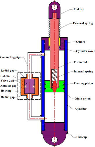
Figure 1. Design of the proposed VSVD-MRFD with annular-radial bypass fluid valve.
Download figure:
Standard image High-resolution image2.2. Working principle
The working principle of the proposed VSVD-MRFD is based on the series connection between the damping of the MRV unit and the spring element as demonstrated in figure 2. The series connection type provides an easy and practical implementation of the VSVD-MRFD in real world applications. The damping variability is realized by controlling the applied magnetic field to the annular-radial bypass MRV. Since the damping element is in series with the internal spring k1, the equivalent damping is not depending only on the damping of the MRV but also, it depends on the stiffness of the internal spring and excitation frequency, as represented in equation (1). The stiffness variability of the proposed damper is also achieved via series connection of MRV unit and the internal spring (k1) which are in in parallel with the external spring element k2. By adjusting the applied current, the force applied on the internal and external springs will be varied. The equivalent stiffness ( ), and equivalent damping (
 ) of the designed MRFD are given in equations (1) and (2), respectively.
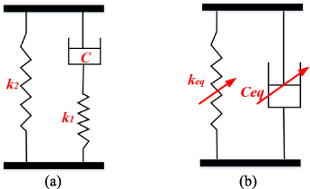
Figure 2. (a) Scheme of the working principle of the VSVD-MRFD, and (b) Equivalent stiffness and damping system.
Download figure:
Standard image High-resolution image2.3. Fabrication of the proposed VSVD-MRFD
The basic geometry of the fabricated VSVD-MRFD is shown in figure 3 and its main dimensions are listed in table 2. Figures 4(a) and (b) show the components and the prototype of the VSVD-MRFD, respectively. The housing cylinder of the damper is fabricated from heat-treated alloy steel 4140 while the carbon steel 1045 was used in the manufacturing of the main piston, piston rod and floating piston. A bronze guider was used to connect the piston rod with the housing cylinder, thereby providing sufficient lubricant for the piston rod during movement. For reducing the magnetic circuit reluctance, a low carbon steel AISI 1117 was used as the material of the bobbin and steel AISI 1006 was used for the shell of the bypass MRV. The spacer material between the bobbin is Nylon 6/6 in the annular gap and stainless-steel SS 304 in the radial gap. These materials properly guide the magnetic flux lines toward active areas in the radial and annular fluid flow channels. Lord Corporation's MRF-132DG MR fluid was utilized to fill the MRFD. The specific gravity of the MR fluid is 3, and its viscosity is 0.112 Pa.s at 40 °C. The electromagnet of the MRV has 215 turns of the copper wire of American Wire Gauge 24. Two heavy duty springs from Lee Company with different stiffness coefficients were utilized to provide stiffness variability. Table 3 shows the detail parameters of the two springs.

Figure 3. Basic dimensions of the proposed VSVD-MRFD.
Download figure:
Standard image High-resolution image
Figure 4. Prototype of the VSVD-MRFD (a) Main components and (b) Assembled VSVD-MRFD filled with MR fluid.
Download figure:
Standard image High-resolution imageTable 2. Main parameters of the proposed VSVD MRFD.
| Parameter | Symbol | Value (mm) |
|---|---|---|
| Duct gab |

| 1.2 |
| Coil width |

| 7.0 |
| Piston diameter |

| 70.0 |
| Piston rod diameter |

| 30.0 |
| Floating piston diameter |

| 19.05 |
| Radial duct outer diameter |

| 38.1 |
| Radial duct inner diameter |

| 10 |
| MR valve whole diameter |

| 64.5 |
| Annular duct length |

| 43.9 |
| Coil length |

| 10.7 |
| MR valve height |

| 60.0 |
Table 3. Specification of the Springs.
| Specification | Internal spring | External spring |
|---|---|---|
| Stiffness | 120.0 N mm−1 | 15.5 N mm−1 |
| Free Length | 44.5 mm | 127.0 mm |
| Outside diameter | 18.29 mm | 42.85 mm |
| Hole diameter | 19.05 mm | 44.45 mm |
| Rod diameter | 9.53 mm | 30.58 mm |
3. Experimental characterization of the VSVD-MRFD
3.1. Test setup
A comprehensive experimental investigation was conducted to evaluate the dynamic performance of the proposed bypass VSVD-MRFD with an annular-radial gap in terms of force-displacement and force-velocity characteristics under a relatively wide ranges of mechanical and magnetic loading conditions. The designed test rig and the specifications utilized in the measurements have been thoroughly explained in the previous study [63]. Briefly, figure 5 shows the full test setup for implementing the dynamic characterization of the VSVD-MRFD. The piston of the damper is attached to the load cell from the top and the lower part of the damper is connected to the lower part of an electro-hydraulic actuator. The input displacement is provided by the actuator and the resulting force is recorded from the load cell. The measured data were then transferred to the PC shown in figure 5, via a data acquisition system (National Instrument Inc). A power supply was employed to provide the required electrical current for the MRV.
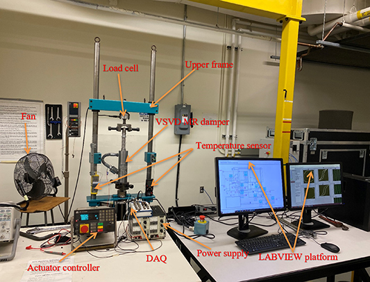
Figure 5. Photograph of the full test setup implemented with the fabricated VSVD-MRFD.
Download figure:
Standard image High-resolution image3.2. Experimental measurements
The experimental measurements were conducted to measure force-time, force-displacement, and force–velocity of the prototyped MRFD under various input motion amplitudes and frequencies, and excitation currents. In particular, the experiments were performed with five levels of excitation frequency (f = 0.5, 1, 2, 3, and 4 Hz), two levels of displacement amplitude (X = 1 and 2.5 mm), and six levels of applied current (I = 0, 0.25, 0.5, 1, 1.5 and 2 A). For each test condition, force-displacement and force-velocity were measured in five consecutive cycles after observing the steady-state data from the LABVIEW software and then averaged for characterization.
4. Results and discussion
4.1. Nonlinear dynamic characterization of the VSVD-MRFD
The nonlinear dynamic hysteresis characteristics of the prototyped VSVD-MRFD under a wide range of loading conditions are provided and discussed in this section. Figure 6 shows the force-displacement and force-velocity characteristics of the VSVD-MRFD at the excitation frequency of 0.5 Hz, and displacement amplitude of 1 mm. The results are presented for different applied electrical currents, ranging from 0 to 2 A. Results show that the force-displacement hysteresis characteristics and the force-velocity curves become more noticeable and enhanced with increasing the applied current. As it can be realized, the area enclosed by the force-displacement hysteresis loops, which represents the amount of energy dissipation per cyclic loading, is substantially increasing with increasing the applied current. This is also confirmed by the slope of the main axis of the force-velocity curves, which correspondingly denotes the equivalent damping, which is increased by increasing the applied current. Similar behavior was also observed at other loading conditions. Figure 6 further demonstrates that under this loading condition, the peak force is increased from about 1.53 kN in the absence of the current to nearly 5.44 kN under current of 2 A, thus yielding a dynamic range of nearly 3.6. The magnetic saturation phenomenon can also be observed as the applied current exceeds 1.5 A. Furthermore, figure 6(a) also shows that the equivalent stiffness of the MRFD increases as the applied current increases from zero to 2 A. The equivalent stiffness represents the slope of the lines that connect the bottom-left point of the hysteresis curves to the top-right point, corresponding to the force at minimum displacement and the force at maximum displacement, respectively.
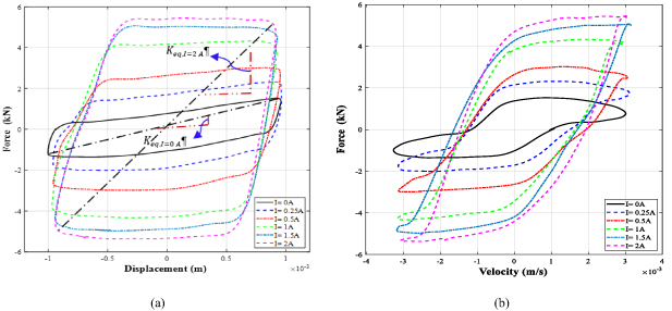
Figure 6. The measured dynamic characteristics of VSVD-MRFD under loading frequency of 0.5 Hz at the displacement amplitude of 1 mm: (a) Force-displacement, and (b) Force-velocity.
Download figure:
Standard image High-resolution imageFigure 7 exhibits variation of the dynamic characteristics of the VSVD-MRFD with respect to applied current at the excitation frequency of 1 Hz and displacement amplitude of 2.5 mm. At this loading condition, the damper's peak force ranges from 2.0 kN to 7.2 kN as the applied current ranges from zero to 2 A, yielding also a dynamic range of 3.6. Results consistently confirm that the enclosed area by the force-displacement loops (energy dissipation) amplifies as the applied current increases. Figures 6(b) and 7(b) also demonstrate that the damping force increases with the increasing velocity of the damper piston rod.

Figure 7. The measured dynamic characteristics of VSVD-MRFD under loading frequency of 1 Hz at the displacement amplitude of 2.5 mm: (a) Force-displacement, and (b) Force-velocity.
Download figure:
Standard image High-resolution imageFigure 8 illustrates the effect of applied current on the dynamic characteristics of the VSVD-MRFD. Results are presented for the excitation frequency of 2 Hz and displacement amplitude of 1 mm. At this loading condition, the damper's peak force ranges between 1.64 kN and 6.73 kN as the applied current ranges from zero to 2 A, representing a higher dynamic range of 4.1. Figures 7(a) and 8(a) also reveal that the slope of the major axis in the force-displacement loops, which corresponds to the equivalent stiffness of the damper, increases as the applied current increases from zero to 2 A, thereby confirming the field-dependency of the stiffness. Moreover, it should be noted that the loading (ABC) and unloading (CDA) paths possess different instantaneous slopes. It is because that the proposed damper has two spring elements, in which when the piston moves within the loading path (e.g. from minimum displacement to zero intermediate position), the spring elements are compressed, thereby varying the slope of loading curves in a piecewise manner (i.e. see the path of AB in figure 7(a)). Increasing the applied current increased the aforementioned slope, as shown in figure 7(a). However, such variation with respect to current was not observed during the unloading path (CD & DA), as expected. The force-displacement curves presented in figure 7(a) show the same slope trends for the unloading path (CD&DA), irrespective of the applied current. Nonetheless, the zero-current force-displacement path shows different path during loading curve (i.e. AB). It is because that the stiffness variation is highly dependent on the applied current. Relatively, similar trends were also observed for other loading conditions, as shown in figure 8(a)
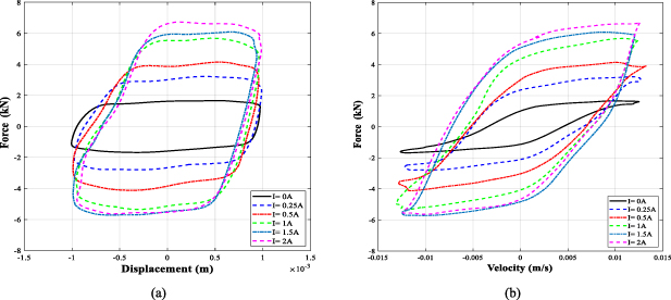
Figure 8. The measured dynamic characteristics of VSVD-MRFD under loading frequency of 2 Hz at the displacement amplitude of 1 mm: (a) Force-displacement, and (b) Force-velocity.
Download figure:
Standard image High-resolution imageFigures 9 and 10 reveal the effect of excitation frequency on the dynamic properties of the VSVD-MRFD in terms of force-displacement and force-velocity characteristics at a constant displacement amplitude of 1 mm under an applied current of 1 A and 2 A, respectively. Results show as the loading frequency increases, the slope of the force-velocity curves, representing the equivalent damping coefficient of the MRFD, decreases. This is due to the fact the equivalent viscous damping is inversely related to the excitation frequency as it will be addressed and quantified in section 4.3. The peak value of the damping force which occurs around zero displacement or near maximum velocity, initially increases noticeably by increasing the loading frequency from 0.5 Hz to 2 Hz, as can be seen both in the force-displacement and force-velocity characteristics (although at different peak velocities) in figures 9 and 10. The peak damping force, however, slightly increases by increasing the loading frequency from 2 Hz to 4 Hz. This is expected as the percentage of increase in the frequency from 0.5 to 2 Hz (300% increase) is substantially more than that from 2 to 4 Hz (100% increase) and also by increasing the frequency the equivalent viscous damping coefficient decreases. It should be also noted that increase in the peak damping force due to increase in the frequency is very small compared with that due to increase in the applied current. This is due to the fact that the excitation frequency affects the viscous damping force which is relatively very small compared with the controllable yield force due to the applied current. As example, the maximum damping forces under displacement of 1 mm, applied current of 2 A and loading frequency of 3 Hz is 6.8 kN which increases to 7.2 kN, by increasing the frequency to 4 Hz.

Figure 9. The frequency-dependent characteristics of the VSVD-MRFD under 1 A electrical current and constant displacement amplitude of 1 mm: (a) Force-displacement, and (b) Force-velocity.
Download figure:
Standard image High-resolution image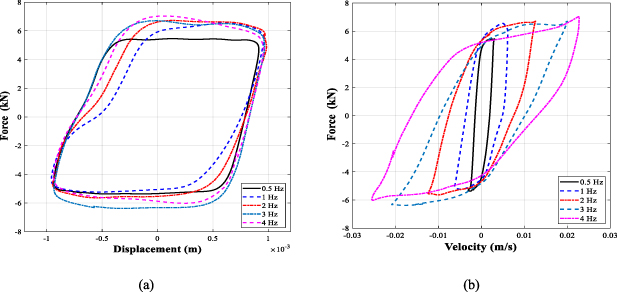
Figure 10. The frequency-dependent characteristics of the VSVD-MRFD under 2 A electrical current and constant displacement amplitude of 1 mm: (a) Force-displacement, and (b) Force-velocity.
Download figure:
Standard image High-resolution imageFigure 10 presents the frequency dependent characteristics of the VSVD-MRFD when 2 A is applied to the MRV's coil. Results show that the excitation frequency yields more nonlinear hysteresis effect on both force-displacement and force-velocity characteristics of the VSVD-MRFD, when higher levels of currents (i.e., 2 A) are applied in comparison to the lower levels of current (i.e., 1 A), as presented in figure 9. For instance, at a higher frequency of 4 Hz, the loading paths of the hysteresis loops presented in figure 10(b), tend to be upward, enhancing the intra-cycle damping coefficient locally. Further analysis of figures 9 and 10 also reveals that increasing the applied current, and thus the magnetic field within the MRV leads to a substantial increase in the energy dissipation properties and damping force of the VSVD-MRFD. Figures 9(a) and 10(a) further reveal that the slope of the force-displacement curves, representing the equivalent stiffness coefficient of the MRFD, slightly increases. It should be noted that the loading and unloading paths of the force-displacement curves relatively show similar trends as observed for non-zero current force-displacement profiles presented in figures 7(a) and 8(a), irrespective of loading frequency. For instance, when the loading frequency increases from 1 Hz to 4 Hz, the slope of the loading path increases, due to the added effect of frequency-dependent friction force of sealing materials within the cylinder-piston assembly, as shown in figures 9 and 10. This can enhance the stiffness of the proposed damper, as the applied current increases within this range.
Figures 11 and 12 explain the displacement dependent properties of the fabricated VSVD-MRFD in terms of force-displacement and force-velocity under excitation currents of 0.5 A and 1.5 A, respectively. Here, these characteristics were studied at a constant excitation frequency of 1 Hz as an example. Results show that the energy dissipation properties and damping force of the VSVD-MRFD is considerably increased by increasing the displacement amplitude from 1 mm to 2.5 mm. Figures 11(a) and 12(a) clearly show the increase in the peak force as the loading displacement increases from 1 mm to 2.5 mm. Figures 11(b) and 12(b) also manifest that the loading paths of the force-velocity curves are relatively independent of the excitation displacement. Similar to figures 9 and 10, the slope of the main axis of the force-velocity loops, which represents the equivalent damping coefficient of the MRFD, tends to decrease with increasing displacement amplitude. The slope of the major axis of the force-displacement loops, which represents the equivalent stiffness, also decreases as the displacement amplitude increases from 1 mm to 2.5 mm.
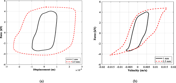
Figure 11. The amplitude-dependent characteristics of the VSVD-MRFD under 0.5 A electrical current and constant loading frequency of 1 Hz: (a) Force-displacement, and (b) Force-velocity.
Download figure:
Standard image High-resolution image
Figure 12. The amplitude-dependent characteristics of the VSVD-MRFD under 1.5 A electrical current and constant loading frequency of 1 Hz: (a) Force-displacement, and (b) Force-velocity.
Download figure:
Standard image High-resolution imageFigure 13 shows the force-displacement and force-velocity characteristics of the prototyped MRFD under a loading frequency of 4 Hz and displacement amplitude of 2.5 mm. It should be noted under these loading conditions, the maximum force generated by the bypass MRFD was reached to as high as 7.82 kN. The damper could not be tested at higher levels of motion frequencies and amplitudes due to the limitation of the electro-hydraulic actuator system and the load cell capacity. Examination of results also reveal that the force-velocity curve presented in figure 13(b) shows secondary or sub-hysteresis loops (cross-over points) at the end of the loading cycle, which is observable at the top-right of the force-velocity curves, irrespective of applied current. These secondary hysteresis loops correspond to peaks in the loading path, which can be seen before and after the intermediate position of zero displacement. It is partly due to the fact that the peak damping force occurred before the instance of the maximum velocity. This implies that the peak force location occurs before the instance of the maximum velocity. This may in part be due to the friction force generated by mechanical friction between the seals and the shaft/piston, as has also been observed in other studies [64–66] and also possibility of slight rocking motion (beside vertical motion) due to the higher frequency vibration. Further, this behavior may also be due to the inertia effect of the MR fluid (1000 ml of MR fluid is contained within the damper) [67, 68], as well as entrapped air in the damper [69–71].
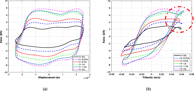
Figure 13. The measured data characteristics of the VSVD-MRFD under loading frequency of 4 Hz at the displacement amplitude of 2.5 mm: (a) Force-displacement, and (b) Force-velocity.
Download figure:
Standard image High-resolution imageThe presentation of the remaining experimental data, including the force-displacement, force-velocity under loading frequencies of 0.5–4 Hz, applied current of 0–2 A, and displacement amplitudes of 1 and 2.5 mm, are presented in Figure 19, 20, 21, 22, and 23 in the
The presented results provide a qualitative analysis of the prototyped VSVD-MRFD. The following subsections will present quantitative assessments of the fabricated VSVD-MRFD in terms of dynamic range, equivalent viscous damping coefficient, and equivalent stiffness coefficient. An investigation of these indices under various loading conditions and magnetic fields is also discussed.
4.2. Dynamic range analysis
The dynamic range is an important figure of merit, indicating the bandwidth and control performance of VSVD-MRFDs to mitigate vibrations under different environmental conditions. The dynamic range is defined as the ratio between the maximum damping force observed at the maximum current applied (Imax) over the minimum damping force at off-state conditions (I = 0 A) [72]. The dynamic range ( ) can, thus, be calculated as:
where  is measured damping force under zero magnetic field, while
  is the measured damping force under maximum applied current. The dynamic range was evaluated under the entire range of the mechanical and magnetic loading conditions considered. Figures 14(a) and (b) illustrate the influence of the excitation displacement and loading frequency on the evaluated dynamic range under different applied currents, respectively. Results clearly reveal that for the given loading condition, the dynamic range substantially increases as the magnetic field increases. This is consistent with the increment in the peak force of the force-displacement observed in figures 6–8. Further examination of results shows that the dynamic range decreases at higher levels of the displacement amplitude and loading frequency, while the influence of displacement is more obvious than that of loading frequency. This is in part due to the greater off-state damping forces at higher loading frequencies and displacement amplitudes, which decreases the dynamic range. Results show that the damper can reach to a maximum dynamic range of 4.5 at the loading frequency of 1 Hz and a displacement amplitude of 1 mm.
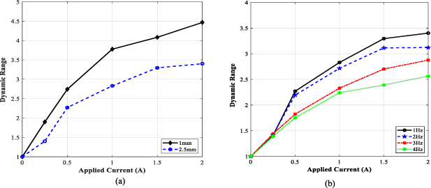
Figure 14. The effect of displacement amplitude and loading frequency on the dynamic range of the VSVD-MRFD under different applied currents: (a) loading frequency of 1 Hz, and (b) displacement amplitude of 2.5 mm.
Download figure:
Standard image High-resolution image4.3. Damping variability
As discussed in section 4.1, the VSVD-MRFD characteristics can be quantified either using the enclosed area of the force-displacement curves (the equivalent viscous damping coefficient ( )) using the energy dissipation method or the slope of the major axis of the force-velocity. The energy dissipation method has traditionally been employed for evaluating the equivalent viscous damping coefficient (
 ) at a certain frequency (
 ). The energy dissipated over one cycle (
 ) can be calculated from the enclosed area of the force-displacement curve as follows [73]:
in which  , and
, and  represent output force, velocity, and displacement, respectively. The equivalent viscous damping coefficient can, thus, be evaluated as [73]:
where  is the displacement amplitude of the input excitation. The
  can be also estimated from the slope of the major axis of the force-velocity curves by finding the damping forces
 ![${\left[ {{F_d}} \right]_{{v_{{\text{max}}}}}}$](https://content.cld.iop.org/journals/0964-1726/32/3/035011/revision3/smsacb474ieqn25.gif) and
and ![$\,{\left[ {{F_d}} \right]_{{v_{min}}}}\,$](https://content.cld.iop.org/journals/0964-1726/32/3/035011/revision3/smsacb474ieqn26.gif) corresponding to the maximum and minimum piston velocity values
corresponding to the maximum and minimum piston velocity values  and
and  respectively as:
The equivalent viscous damping was evaluated using the above two approaches for a loading frequency of 2 Hz and was summarized in table 4, as an example. Results show that the equivalent viscous damping evaluated using both approaches are nearly comparable. Such comparison has been rarely reported in the literature. It was found that the maximum relative difference between the two approaches was almost 2.1%. Furthermore, increasing the excitation displacement leads to a decline in the  confirming the observation in figures 11 and 12. This decrement is also consistent with the force-displacement and force-velocity characteristics presented in figures 6–8.
Table 4. The calculated equivalent viscous damping coefficient ( ) of the MR damper using two approaches.
| Amplitude | Applied current | Energy dissipated method (kN s cm−1) | The slope of idealized force-velocity (kN s cm−1) |
|---|---|---|---|
| 1 mm | 0.0 A | 1.44 | 1.35 |
| 0.5 A | 3.18 | 3.21 | |
| 1.0 A | 3.98 | 4.05 | |
| 2.0 A | 4.86 | 5.06 | |
| 2.5 mm | 0.0 A | 0.75 | 0.78 |
| 0.5 A | 1.59 | 1.66 | |
| 1.0 A | 2.03 | 2.08 | |
| 2.0 A | 2.22 | 2.25 |
The influence of loading displacement and frequency on the variation of the  versus applied current is shown in figures 15 and 16. For instance, figures 15(a) and (b) show the variation of the calculated
  based on the two approaches, considering different displacement amplitudes of 1 mm and 2.5 mm, as a function of applied current. Results indicate a significant decrease in the
  as displacement amplitude increases. This is consistent with the qualitative analysis presented in figures 11 and 12.
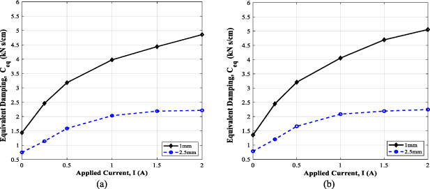
Figure 15. The variations of the calculated the equivalent viscous damping coefficient with respect to applied current considering different displacement amplitudes under loading frequency of 2 Hz: (a) Energy dissipated method, and (b) Linearized force-velocity curve.
Download figure:
Standard image High-resolution image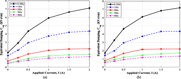
Figure 16. The variations of the calculated the equivalent viscous damping coefficient with respect to applied current considering varied loading frequencies under displacement amplitude of 2.5 mm: (a) Energy dissipated method, and (b) Linearized force-velocity curve.
Download figure:
Standard image High-resolution imageFurthermore, figures 16(a) and (b) show the variations of calculated  versus applied current for various loading frequencies, ranging from 0.5 Hz to 4 Hz, calculated by two aforementioned methods. Results reveal a nonlinear increment in the
  with increasing applied current while it diminishes for higher loading frequency, which confirms the observation in section 4.1 (see figures 9 and 10). For instance, the
  at zero current and displacement amplitude of 2.5 mm under loading frequency of 0.5 Hz and 3 Hz were respectively obtained as 1.69 kN s cm−1 and 0.67 kN s cm−1. The corresponding
  at applied current of 2 A were obtained as 7.18 kN s cm−1, and 1.70 kN s cm−1, respectively. These reveal the relative increments of 425%, and 253% at 0.5 Hz and 3 Hz, respectively, when applied current increased from zero to 2 A. A closer examination of figures 15 and 16 also reveal that the
  is prone to magnetic saturation when applied current exceeds 1.5 A. This is also consistent with saturation magnetization within force-displacement curve (e.g. peak force) observed in figure 7.
4.4. Stiffness variability
The proposed VSVD-MRFD is also characterized to examine its stiffness variability by evaluating the equivalent stiffness of the system. MRFD featuring stiffness variability can be effectively utilized to significantly reduce the transmitted vibration by varying the natural frequency of the system to avoid resonance occurrence. Moreover, it can also overcome the conflict between good handling and ride comfort for off/on-road vehicles [74, 75]. The equivalent stiffness ( ) of the fabricated VSVD-MRFD can be evaluated from the slope of the axis line intersecting the point at maximum and minimum force-displacement hysteresis cycle (See figure 6). This slope is varied according to the applied current and can be estimated from the following equation as [34]:
where ![${\left[ {{F_{\text{d}}}} \right]_{{D_{{\text{max}}}}}}$](https://content.cld.iop.org/journals/0964-1726/32/3/035011/revision3/smsacb474ieqn42.gif) and
and ![${\left[ {{F_{\text{d}}}} \right]_{{D_{{\text{min}}}}}}$](https://content.cld.iop.org/journals/0964-1726/32/3/035011/revision3/smsacb474ieqn43.gif) denote the maximum and minimum forces generated by the damper, respectively, corresponding to the maximum and minimum value of the stroke, namely,
denote the maximum and minimum forces generated by the damper, respectively, corresponding to the maximum and minimum value of the stroke, namely,  and
and  .
.
Figures 17 and 18 exhibit the variation of  of the VSVD-MRFD with respect to the applied current considering different levels of loading displacement and frequency. For example, figures 17(a) and (b) reveal the influence of the excitation displacements of 1 mm and 2.5 mm on the evaluated
  at loading frequencies of 1 Hz and 2 Hz, respectively as a function of the applied current. The results indicate that the
  significantly increases as the current increases. However, similar to the equivalent viscous damping, the rate of increasing is reduced as the applied electric current increases from 1 A to 2 A indicating the magnetic saturation phenomenon. Moreover, results reveal a remarkable reduction in the
  as the excitation displacement increases. This decrement is also consistent with the observed decrements of the slope of the major axis of the force-displacement in figures 11(a) and 12(a).

Figure 17. The variations of the calculated equivalent stiffness coefficient ( ) with respect to applied current considering different displacement amplitudes: (a) loading frequency of 1 Hz, and (b) loading frequency of 2 Hz.
Download figure:
Standard image High-resolution image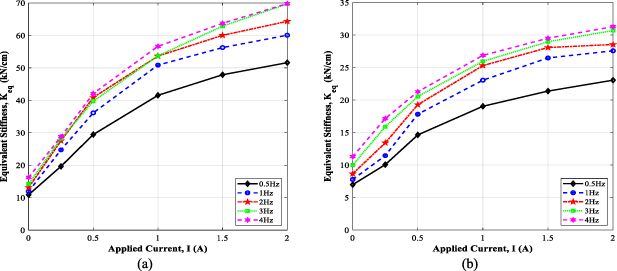
Figure 18. The variations of the calculated equivalent stiffness coefficient ( ) with respect to applied current considering varied loading frequencies: (a) displacement amplitude of 1 mm, and (b) displacement amplitude of 2.5 mm.
Download figure:
Standard image High-resolution image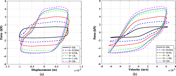
Figure 19. The measured dynamic characteristics of VSVD-MRFD under loading frequency of 1 Hz at the displacement amplitude of 1 mm: (a) Force-displacement, and (b) Force-velocity.
Download figure:
Standard image High-resolution image
Figure 20. The measured dynamic characteristics of VSVD-MRFD under loading frequency of 2 Hz at the displacement amplitude of 2.5 mm: (a) Force-displacement, and (b) Force-velocity.
Download figure:
Standard image High-resolution image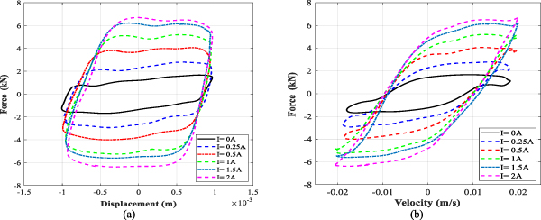
Figure 21. The measured dynamic characteristics of VSVD-MRFD under loading frequency of 3 Hz at the displacement amplitude of 1 mm: (a) Force-displacement, and (b) Force-velocity.
Download figure:
Standard image High-resolution image
Figure 22. The measured dynamic characteristics of VSVD-MRFD under loading frequency of 3 Hz at the displacement amplitude of 2.5 mm: (a) Force-displacement, and (b) Force-velocity.
Download figure:
Standard image High-resolution image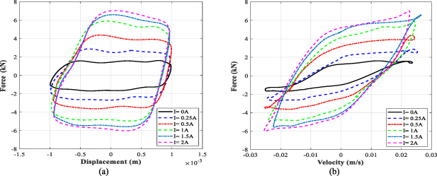
Figure 23. The measured dynamic characteristics of VSVD-MRFD under loading frequency of 4 Hz at the displacement amplitude of 1 mm: (a) Force-displacement, and (b) Force-velocity.
Download figure:
Standard image High-resolution image
Additionally, figures 18(a) and (b) show the variation of the evaluated  under various loading frequencies, ranging from 0.5 Hz to 4 Hz, as a function of the applied current, calculated for excitation displacements of 1 mm and 2.5 mm, respectively. Results also reveal a nonlinear increasing in
  with increasing the applied current. Results also show that the increment in
  with respect to current is more pronounced at higher levels of applied frequency. For example, the
  at zero current and displacement amplitude of 1 mm under loading frequency of 0.5 Hz and 3 Hz were respectively obtained as 10.90 kN cm−1, 14.26 kN cm−1. The corresponding
  at applied current of 2 A were obtained as 51.60 kN cm−1, and 69.70 kN cm−1, respectively. These reveal the relative increments of 473%, and 488% at 0.5 Hz and 3 Hz, respectively, when the applied current increased from zero to 2 A. Further observation of figures 17 and 18 reveals that the
  has a tendency to saturate when applied current exceeds 1.5 A.
The  was quantitatively evaluated for loading frequency of 1 Hz and displacement of 2.5 mm under various applied currents and was summarized in table 5, as an example. Results show the wide range variability of the
  with the applied current. The equivalent stiffness increases from 7.78 kN cm−1 at zero current to almost 27.57 kN cm−1 at the applied current of 2 A, rendering a dynamic range of almost 3.5 in view of stiffness.
Table 5. Equivalent stiffness coefficient under different applied currents.
| Applied current | Equivalent Stiffness,  (kN cm−1) (kN cm−1) |
|---|---|
| 0 | 7.78 |
| 0.25 | 11.44 |
| 0.5 | 17.81 |
| 1 | 23.05 |
| 1.5 | 26.47 |
| 2 | 27.57 |
5. Conclusion
In this work, a novel VSVD-MRFD featuring annular-radial bypass MRV was experimentally characterized over a wide range of loading conditions and applied currents. The force-displacement and force-velocity response behaviors of the VSVD-MRFD were discussed as functions of varied loading conditions and applied currents. The proposed VSVD-MRFD exhibits increasing peak forces and areas enclosed by force-displacement hysteresis loops as the loading frequency, displacement amplitude, and current increase. The dynamic range, equivalent viscous damping coefficient and equivalent stiffness coefficient were quantitatively evaluated over the entire range of loading conditions. Additionally, results reveal that both the equivalent viscous damping and dynamic range increase as the applied current increase, whereas they decrease with increasing loading frequency and displacement amplitude. The observed decrement was more noticeable with increasing the displacement amplitude. Results further demonstrate that the proposed VSVD-MRFD has a high uniformity and good performance, and provide wide stiffness variability in view of mechanical and magnetic loadings. The equivalent stiffness significantly increases as the applied current increases. Results also show that equivalent stiffness increases slightly with increasing the loading frequency while substantially decreases with increasing displacement amplitude. The maximum relative increase in the  and
and  were obtained as 425% and 488%, when applied current increased from zero to 2 A. Based on the presented results, the concept of large-capacity VSVD-MRFD has been accomplished in a compact design. Results also suggest that the proposed VSVD-MRFD can be effectively utilized in off-road vehicle suspension systems for avoiding harmful vibration under different environmental conditions. It should also be noted that the proposed design innovation offers a simple design modification of the bypass MRV for realizing wide scalability of damping force, and thus facilitate the development of adaptive off-road vehicle suspensions, landing gear, or shock absorbing suspension systems.
Acknowledgments
This work was supported by the Natural Sciences and Engineering Research Council (NSERC) and Department of National Defense (DND) of Canada, under Grant Nos. RGPIN and DGDND-2021-03482.
Data availability statement
The data that support the findings of this study are available upon reasonable request from the authors.